c
Owned by the authors, published by EDP Sciences, 2015
A 3-D perspective of dynamic behaviour of heterogeneous solids
Yong Luaand Rongxin Zhou
Institute for Infrastructure and Environment, School of Engineering, The University of Edinburgh, The King’s Buildings, Edinburgh EH9 3JL, UK
Abstract. The dynamic behaviour of concrete-like materials under high strain rates has been a subject of continuous scrutiny over the years. A prevailing explanation attributes much of the dynamic increase of strength, especially under compression, to the macroscopic inertia confinement. Studies conducted by the authors’ group using meso-scale computational models suggest that the heterogeneity of the material composition, in particular the involvement of the aggregates, also plays a sensible part in the process of damage evolution and the increase of the bulk strength under high strain rates, and a detailed investigation into this effect would benefit if a realistic representation of the heterogeneity in 3D can be achieved. This paper presents some recent progress in the development of a 3-D meso-scale computational model incorporating randomly-shaped 3-D aggregate particles, including the general validation of the model, and application in the simulation of the dynamic response of concrete under high strain rate compression.
1. Introduction
Concrete is highly non-homogenous material with large heterogeneities. Generally speaking, the description of concrete may be classified into three distinctive scales, namely macroscale, mesoscale and microscale. On the macroscale concrete is considered as homogeneous material and treated as such in classical finite element models. On the mesoscale concrete is considered as a composite material comprising of coarse aggregate, mortar matrix and the interfacial transition zone (ITZ). A mesoscale model permits a direct description of the material heterogeneity and hence allows for a realistic prediction of the development of damage within the muti-phase material. At a microscopic level, the mortar matrix is further divided into fine aggregates and hardened cement paste with pores embedded inside. As far as the composite mechanical behaviour is concerned, sub-division of the individual phases does not appear to introduce significant effect [1], and hence modelling of concrete on a mesoscale is deemed to be an effective choice when material heterogeneity needs to be taken into account.
A number of studies on the 2D mesoscale modelling of concrete can be found in the existing literature (e.g. [1,2]. However, 2D mesoscale modelling of concrete-like material has inherent limitation in representing a realistic stress and strain field in concrete specimen, particularly with regard to the lateral inertial confining effect in dynamic loading. Thus a pseudo 3D model has been developed and applied in the analysis of the strain rate effect under dynamic compression in [3]. Understandably, a true 3D mesoscale model is a more desirable solution in representing the material heterogeneous structures and giving more reliable results. However, modelling the random mesoscale structure of concrete in 3D is considerably more complex.
aCorresponding author:[email protected]
The primary difficulty arises from the representation of a random aggregate structure. To circumvent this difficulty, simple shapes of aggregate particles like spheres or mixed spheres and ellipsoids are mostly used in previous research. Further proposal of a modified version of the ellipsoid function [4] made it possible to better approximate real aggregates. Recently a more accurate approximation of particle shapes represented by polyhedrons has been adopted by some researchers. This method can approximate the real aggregate shape better than simple spheres and ellipsoids but it cannot satisfy the size grading curve. Direct mapping of the aggregate particles from physical samples has been explored using computer image analysis and computed tomography (CT-scan).
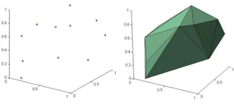
Figure 1. An example convex Hull.
The model is then applied to simulate the dynamic compressive behaviour of concrete under high strain rate compression.
2. Generation of the 3D mesoscale
geometry with random aggregates
2.1. Basic operations
The generation of the 3D mesoscale model involves first of all the creation of 3D aggregates in random shapes and sizes following prescribed distributions and packed to a desired density, or volumetric ratio. The procedure for the creation of the 3D mesoscale model geometry follows the commonly used “take and place” routine in a sequential manner, starting with the largest aggregate size group, and carry on until the smallest size group is fulfilled.
In the present work, we create the aggregate particles by bounded polyhedrons. The convex hull for a set of points is the minimum convex polyhedron containing all the predefined points. Thus it is possible to generate a random shaped aggregate particle from a set of 3D random points. The number of the points which are used to generate a polytope can be varied. A larger number of random points are used to produce gravel shapes while a relatively small number of points are used for angular shapes of aggregates. The convexity of the polyhedron can be automatically fulfilled without separate checking at every step. Furthermore, the take and place procedure is used to guarantee a prescribed aggregate size grading according to the Fuller curve. Figure1 gives an example of a convex hull generated by Matlab with a computational geometry function named Qhull.
The shapes of aggregate particles created above are in-polyhedrons of spheres, which are relatively regular. Both flaky and elongated aggregates can be realised from the regular polytopes by shrinking or elongation. The Euler anglesα β andγ, which represent the coordinate system rotation in R3 are utilised to ensure the shrinkage or the
elongation to take place in a random direction, not just limited along x, y and z axes.
After generating an individual aggregate particle, the ‘place’ process is carried out. In this process, the aggregate generated from the “take” process is positioned into the predefined concrete space in a random manner, subjected to prescribed physical constraints. The most important and time consuming step in the placing process is the intersection checking between two polytopes. Clearly it is neither economical nor necessary to check each newly placed aggregates against all existing aggregates
for intersection. Thus a pre-selection algorithm is used to identify the existing polytopes that may have a chance to intersect with the one being placed. A local checking space is defined as a bounding sphere which shares the same centre with convex hull and covers all vertices of the polytope. Subsequent intersection check only needs to be carried out for polytopes whose bounding spheres intersect with that of the current particle.
A linear time algorithm is then employed to determine the distance between two convex hulls. The algorithm is based on a hierarchical representation of polyhedrons. Once the hierarchical representation is constructed, it is possible to detect the intersection condition by iteratively calculating the minimum distance which is not necessarily on the vertices between two particles.
2.2. Enhancement on the placing of aggregates
In the existing “place” procedure, once an aggregate being placed is found to intersect with any existing aggregates, this aggregate will be abandoned and a new polytope is regenerated and placed into a new position, and the checking process is carried out all over again. This cycle continues until no intersection occurs. In order to increase the success rate of placing the aggregate and improve the placing efficiency, a translate-and-rotate procedure is employed on the aggregate which is being placed The detail of this procedure is described as follows:
For the random translating procedure, point Pi(Xi, Yi, Zi) is firstly defined as a coordinate of any one vertex of the particle which will be placed in the concrete specimen. Then a small distance is translated on the particle. Thus the coordinate of the vertex after moving should beQi(Xm, Ym, Zm) where
0<Xi,Yi,Zi <50; 0<Xm,Ym,Zm<50; (1) and
−1.5<Xm−Xi,Ym−Yi,Zm−Zi<1.5, (2) Here a value of 1.5 is chosen for limiting the translating procedure in a certain space.
For the random rotating procedure, according to Euler’s rotation theorem, any rotation in 3-dimenisonal Euclidean space can be achieved by three elemental rotations. Thus three random degrees α,β,γ which are defined as the random rotating degrees about x, y and z axis, respectively, are introduced to locate the aggregate particle after rotating. The coordinate of a vertex after rotating can be expressed as
Ri =Z (γ)Y (β)X (α)Pi. (3) And the final expression of the coordinate is
Ri =
cossi nγγcoscosαα−cossi nγγcoscosββsi nsi nααcoscosγγsi ncosαβ+cossi nα γsi ncosγβsi ncosααcossi nγγsi nsi nββ si nαsi nβ −si nβcosα cosβ
Pi
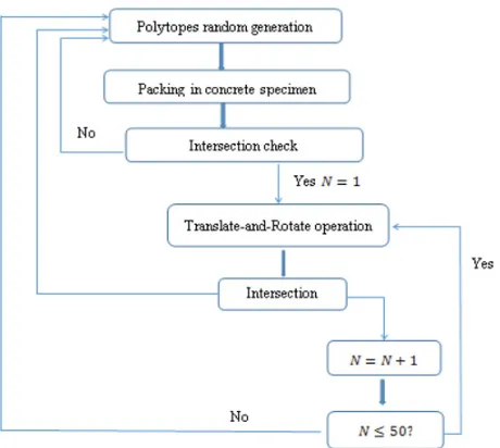
Figure 2. Flow chart of the placing procedure including translate-and-rotate operation.
It should be noted here the translate-and-rotate procedure does not guarantee the condition of no intersection between two particles. A limited number of translate-and-rotate operations can be set to avoid being trapped into useless attempts. From the trial analysis in the present study, a limit of 50 times appears to be adequate. Figure 2presents a flow chart for the “take and place” procedure incorporating the adjustment operation.
When compared with the procedure without consid-eration of the translate-and-rotate method it is found that the translate-and-rotate procedure not only reduces the computing time but also effects to increase the aggregate volume percentage significantly. When a high volume ratio of aggregates is desired, however, the procedure would become extremely time-consuming or even fail. Thus a alternative approach would be needed to further increase the aggregate percentage, and this will be touched upon later.
3. Finite element meshing and
generation of supplementary aggregates
Another challenge for 3D mesoscale modelling of concrete is to discretise the specimen into elements strictly according to different phase boundaries. Due to the existence of randomly shaped aggregate particles, the meso-structure is highly unstructured. For meshing unstructured domain, triangle and tetrahedral meshing are mostly used in the gird refinement. Specific smoothing algorithms for meshing unstructured domain include Octree, advancing front and Delaunay refinement. A typical way to work around the difficulty arising from meshing directly the highly unstructured mesoscale geometry is by firstly performing a background meshing and then bundling groups of the meshed elements into aggregates of targeted (or mapped) shapes. The obvious drawback of such an approach is that the actual surfaces of the aggregates cannot be preserved and instead saw-tooth shaped boundaries will result. Consequently the
Figure 3. Example of 3D mesoscale structure and meshing results.
interaction between aggregates and mortar matrix becomes unrealistic which can in turn affect the representation of the mesoscopic failure mechanisms. In the present mesoscale model we endeavour to mesh the mesoscale structure of concrete directly. An advanced meshing code, called TetGen [6], is employed to do this task. The advantage of using this mesh method is that it can ultimately retain realistic boundaries between aggregate and mortar. This provides an essential basis for the simulation of stress concentration, crack initiation and damage accumulation in concrete from a mesoscopic perspective. Figure3shows an example of the 3D structure and meshing results of a cubic concrete specimen. Note that up to this point only aggregate and mortar elements have been generated; the polytope particles represent the aggregates and the remaining domain belongs to the mortar material.
Figure 4. ITZ layer; left=3D view, right=a plane cut view.
A practical restriction to the take-and-place method in 3D meso-scale modelling is that the packing density is low and it is difficult to achieve a realistic aggregate volume ratio of 40–50%. From our experience the maximum aggregate volume ratio that may be achieved from the standard take-and-place procedure described earlier is around 30%. Therefore, additional aggregates need to be created to augment the aggregates and increase the total volume ratio. In the present work we propose to create additional aggregates from the mortar domain by grouping mortar elements to form secondary aggregates in a quasi-random manner. The detail of this procedure is reported in a separate paper. Through this approach, high aggregate volume ratio to the order of 50–60% may be achieved.
4. FE analysis using the mesoscale
model
In the present analysis 3D mesoscale model for a 50-mm cubic specimen of concrete is developed. This sample size is typical in dynamic testing of concrete for high strain rate loading. The specimen is subjected to simulated quasi-static test before it is used for the simulation under high strain rate loading. Considering computational stability (especially in large deformation range) and that the mesh size in the 3D mesoscale model is usually considerably fine, 4-node tetrahedron element is used in the simulations. 4.1. Material models
At the mesoscopic level, damage and the nonlinear behaviour occur primarily in the mortar matrix and along ITZ. Therefore a suitable material model for these two phases is important for the final simulation results. The material model employed for the two parts in this study is the K&C Concrete Damage Model, also known as material #72R in LS-DYNA. The material model is capable of describing the material failure due to tension, shear, as well as compression under various stress conditions, and it also includes pressure and strain rate dependent features. The detail information of this material model can be found in [7]. The material model has been tested extensively and is found to be a suitable candidate for quasi-static as well as dynamic applications.
The coarse aggregates usually have significantly higher strength than mortar. It is deemed to be reasonable to use a linear elastic material model for aggregates under low rate loadings. However for high dynamic loading such as shock and blast, the rapid propagation of stress
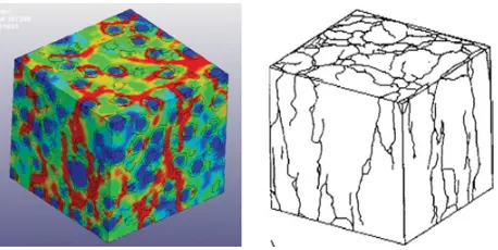
Figure 5. Damage patterns under lower loading-face friction: left
=simulated, right=experimental (after [9]).
wave could result in high stresses being developed in aggregates in a very different way as compared to low rate loading conditions, and this could subject the aggregates to potential failure [8]. Under this circumstance, a nonlinear material model becomes necessary. Herein we also use the concrete damage model for aggregates with however failure strength matching that of the chosen aggregate type.
4.2. Model configurations
To simulate the uniaxial loading condition, the specimen is fixed at the bottom face and loaded from the top edge in the vertical (z) direction. In order to be able to produce the full range of the concrete response including the softening stage, the loading is applied in a displacement-controlled mode by imposing a velocity boundary condition. The transient analysis code LS-DYNA is employed to perform the simulation using an explicit time integration procedure, which enables an easy realisation of dynamic loading.
5. Model verification and application in
analysis of concrete under high strain
rate compression
5.1. Verification under quasi-static compression
Experimental results show that the compressive behaviour of concrete specimen can be strongly influenced by frictional restraint between specimen and loading platen which is known as loading-face friction effect. The present 3D mesoscale model is also examined by this effect as a basic model validation against relevant experimental observations.
As can be seen in Figure, the damage pattern from the simulation using the mesoscale model agrees well with the experimental result. Under the uniaxial compression with a lower friction boundary condition, a series of column-type of fractured blocks occurred in the concrete specimen because of the formation of the -cracks almost parallel to the applied load. Similar agreement between the simulated and experimental results for higher friction cases has also been achieved (not shown here).
5.2. Dynamic compression
the increase of the strain rate. A Dynamic Increase Factor (DIF), which is defined as the ratio of the apparent dynamic strength to the static strength of the sample specimens, is commonly used to account for the strength enhancement due to high strain rates. However, the true mechanism underlying the occurrence of the DIF is still a subject of continued debate.
As far as dynamic compression is concerned, various analytical and numerical studies in more recent years suggest that that the lateral inertial confinement plays a key role in the enhancement of the dynamic compressive strength (e.g. [10,11]). More recent numerical studies using 2D mesoscale models provide further support to this argument (e.g. [3]). However, 2D mesoscale model has inherent limitation in the representation of the lateral inertial confinement. A pseudo 3D model proposed in (Lu and Song), in which a slice of 2D mesoscale model is sandwiched between two halves of homogeneous models, made it possible to retain the mesoscale features within the plane of interest while lateral inertia can develop naturally in a 3D environment. However, clearly a true 3D mesoscale model is a more desirable solution in representing more robustly the material heterogeneity and enabling more reliable results.
The present 3D mesoscale model is therefore employed to simulate the dynamic behaviour of a concrete specimen under dynamic compression. For a comparison, a 2D homogeneous model, a 2D mesoscale model and a 3D homogeneous model are also analysed for the same variation range of the strain rates. For an un-altered observation of the contribution of the structural inertial effect, the constituent materials are considered to be rate insensitive, i.e., no embedded strain rate enhancement factor is adopted in the material properties in all the models. Thus any increase in the nominal (apparent) compressive strength of the simulated test specimen is attributable only to the sample-wide dynamic effect, as well as the material heterogeneity. The nominal dynamic compressive strength is evaluated from the average stress on both the loading and supporting faces, and the stress on these two faces is in turn calculated as the total nodal force in the axial direction divided by the cross-section area. This effectively resembles the “three-wave” approach in evaluating the stresses from the standard SHPB tests.
The dynamic loading is simulated by applying a velocity boundary condition in a similar way as in the quasi-static analysis, but with a high velocity and a different time history in order to achieve a desirable strain rate and stress distribution. Note that in the dynamic simulation herein, no friction induced lateral confinement is considered at the loading face.
Figure 6 shows the variation of the predicted DIF with the strain rate from the simulations using the models mentioned above. Comparison also includes four empirical equations on DIF of concrete, namely a) CEB-FIP DIF model, b) and c) two empirical models, and d) a semi-empirical model.
It is worth mentioning here that the strain rate analysed in SHPB-like compression tests should be limited by the dimension (length) of the specimen. In the current numerical experiment, the dimension of concrete specimen
Figure 6. Predicted DIF with the strain rate.
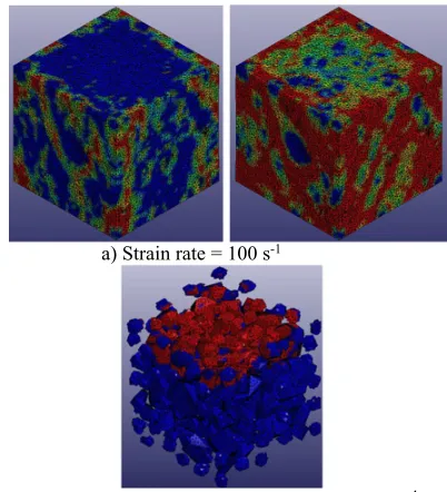
a) Strain rate = 100 s-1
b) Damage in aggregates, strain rate = 400 s-1
Figure 7. Damage contours from 3D mesoscale model.
is 50 mm for which a strain rate up to about 100 s−1 is
considered as acceptable The simulations in the higher strain rate range do not satisfy the stress equilibrium and strain uniformity requirements for the size of the specimen. Therefore the DIF results in this range may be considered for a reference purpose only.
As can be observed from Fig. 6, all models exhibit a significant increase in the nominal compressive strength as the strain rate increases, despite that no strain rate enhancement has been incorporated in the material constitutive model. The general trend of the DIF curves in numerical models resemble well with the curves given by the empirical formulas. The 3D mesoscale tends to predict the upper bound DIF among all numerical results, and this is deemed to be attributable to the enhanced contribution from the aggregates.
6. Conclusions
This paper reports the latest progress in the development of a comprehensive 3D mesoscale model framework for modelling of concrete allowing the realisation of practically any shapes and packing density of aggregates. The enhancements include improved packing efficiency by incorporating a translate-and-rotate algorithm in the placing operation, and increased packing density by creating secondary aggregates from the meshed mortar domain in a quasi-random manner. Furthermore, an efficient meshing program is adopted to perform direct meshing of the highly unstructured mesoscale geometric domains.
3D mesoscale model is then generated for the analysis of a representative 50-mm cubic specimen. The model is subjected to quasi-static compression, as well as tension (not shown in this paper), and results are found to agree favourably with typical experimental observations. The model is subsequently applied to simulate dynamic compression under high strain rates. The simulation results provide a full 3D perspective of the stress wave phenomenon and evolution of damage in a realistic 3D perspective. It further demonstrates that the mesoscopic heterogeneity can make a significant contribution towards the overall dynamic increase factor (DIF) under high strain rate compression.
The 3D mesoscale model provides a robust modelling platform for investigation into micro-mesoscopic mech-anisms for concrete as well as general heterogeneous composites under dynamic loads.
References
[1] Z. Tu, and Y. Lu, Mesoscale modelling of concrete for static and dynamic response analysis Part 1: model development and implementation. Structural Engineering and Mechanics, 37(2), 197–213 (2011) [2] Z.M. Wang, A.K.H. Kwan, and H.C. Chan,
Mesoscopic study of concrete I: generation of
random aggregate structure and finite element mesh. Computers & Structures, 70(5), 533–544 (1999) [3] Y. Lu, Z. Song and Z. Tu, Analysis of dynamic
response of concrete using a mesoscale model incorporating 3D effects, International Journal of Protective Structures, 1(2), 197–218 (2010)
[4] S. H¨afner, et al., Mesoscale modeling of concrete: Geometry and numeric, Computers & structures, 84(7), 450–461 (2006)
[5] Z. Song, and Y. Lu, An algorithm for generation of 3D mesostructure of concrete for finite element analysis, in 19th UK ACME Conference, Edinburgh, UK (2011)
[6] H. Si, A Quality Tetrahedral mesh generator and 3D Delaunay triangulator Version 1.5, User’s Manual (2013)
[7] L.J. Malvar, J.E. Crawford and K.B. Morrill, K&C concrete material model release III - automated generation of material model input, Technical Report TR-99-24.3, Karagozian & Case (2000)
[8] Z. Song, and Y. Lu, Mesoscopic analysis of concrete under excessively high strain rate compression and implications on interpretation of test data, International Journal of Impact Engineering, 46, 41– 55 (2012)
[9] van Vliet, M.R. and J.G. van Mier, Experimental investigation of concrete fracture under uniaxial compression, Mechanics of Cohesive-frictional Ma-terials, 1(1), 115–127 (1996)
[10] F.V. Donze, S.-A. Magnier, L. Daudeville, C. Mariotti and L. Davenne. Numerical study of compressive behavior of concrete at high strain rates. J Eng Mech – ASCE, 125, 1154–63 (1999)