Volume 2, No. 4, July-August 2011
International Journal of Advanced Research in Computer Science
RESEARCH PAPER
Available Online at www.ijarcs.info
A Fast DOA Estimation Based on Space-Time Direct Data Domain Approach Using
Real Antenna Elements
Hassan Elkamchouchi
Department of Electrical EngineeringAlexandria University, Alexandria, Egypt [email protected]
Darwish Mohamed
Department of Electronics and Communications Engineering Arab Academy for Science and Technology (AAST)
Alexandria, Egypt [email protected]
Wael Ali
*Department of Electronics and Communications Engineering Arab Academy for Science and Technology (AAST)
Alexandria, Egypt [email protected]
Abstract: Space Time Adaptive Processing (STAP) applied on signals received from different configurations of real elements using D3LS (Direct Data Domain Least Squares) in order to estimate the direction of each incoming signal. The algorithm deals with the actual desired signals as interferences and we can easily detect their directions. We use a preprocessing technique before applying D3LS STAP approach for elimination the mutual coupling effect between elements due to the use of real antenna elements. Five different antenna configurations are used: uniform linear equal spaced array, exponential spaced linear array, semicircular array, sinusoidal spaced array, and planar array. Numerical simulations are done using the three main methods of D3LS namely the forward, backward, and the forward–backward methods.
Keywords: Direct Data Domain Least Squares (D3LS), Space Time Adaptive Processing (STAP)
I. INTRODUCTION
Generally, in mobile communication and radar application, Conventional DOA estimation algorithms such as MUSIC usually need hundreds of snapshots. In some algorithms, the matrix inversion operation may be made. Therefore, these algorithms are time-consuming and it's difficult for them to meet high real-time requirement [1]. Initially, EM principles are applied to compensate for the effects of mutual coupling including the effect of nonuniformity in spacing between the antenna elements. This preprocessing technique transforms the voltages that are induced in the non-uniformly spaced array containing real elements due to all incoming signals to a set of voltages that would be induced by a Uniform Linear Virtual Array (ULVA) containing isotropic point sources [4].
Recently, a D3LS is widely used for adaptively enhancing signals in STAP. Compared with traditional STAP approaches, this method operates on a snapshot by snapshot basis to determine the adaptive weights instead of training data from neighbor range cells and is proved to be an effective way in non-stationary environment [11].
For airborne radars, the detection of moving targets is a primary objective. During detection, the radar encounters the effect of strong interference which will affect on the estimation of signal. If the radar platform is stationary, the effect of the interference can easily be removed. However, when the platform is nonstationary, the space-time adaptive processing (STAP) has been developed to address these applications [8]. STAP is carried out by performing two-dimensional (2-D) filtering on signals that are collected by simultaneously combining signals from the elements of an antenna array (the spatial domain) as well as from the
multiple pulses from a coherent radar (the temporal domain) [9].
In this paper, we exploit the characteristic of the D3LS that it has good nulling capability even for coherent signals with single snapshot. We add a virtual desired signal to the receiving data. At the same time, the actual desired signals are regarded as interferences. We use the D3LS STAP algorithm to get nulls on the direction of the actual desired signals while restricts the mainlobe on the direction of the virtual source. Five antenna configurations are used: Uniform Linear Equal Spaced Array (ULESA), Exponential Spaced Linear Array (ESLA), a Semicircular Array (SCA), Sinusoidal Spaced Array (SSA), and Planar Array. D3LS STAP will be applied on the measured voltages from these configurations.
II. SYSTEMMODEL
Assume that U+ 1 source impinging on an array of real elements antenna from distinct azimuthal directionsϕ0,...,ϕU. So in addition to SOI there are U undesired signals. We will deal with five array configurations of real elements and each configuration consists of N elements. In ESLA the distance between elements is set to
Dn =dexp(nδ) n=1,2,...,N−1 (1) where d is the distance between elements in the virtual array and δ is a constant.
A Single snapshot of the voltages represents a 1
×
[ ]
∑
[
( )
] [ ]
=−
+ =
=
U
u
u u
N
t a
t s
t x
t x
t x
t x
0
1 1 0
) ( )
(
) (
) (
) (
)
( ϕ ζ
(2)
where su(t)denotes the signal at the elements of the array from the uth source, for u=0,....,U . [a(ϕ)]denotes the steering vector of array toward the azimuth direction ϕ
and
[ ]
ζ(t) denotes the noise vector at each of the loaded antenna elements.Figure.1 Geometry of ULESA and its equivalent ULVA
Figure.2 Geometry of ESLA and its equivalent ULVA
Figure.3 Geometry of SCA and its equivalent ULVA
Figure.4 Geometry of SSA and its equivalent ULVA
Figure.5 Geometry of planar array and its equivalent ULVA
By using a matrix representation (2) becomes
[ ] [
x(t) = A(ϕ)][ ] [ ]
s(t) + ζ(t) (3) Where[A(ϕ)] of size N×(U+1)referred to as the array manifold corresponding to each one of the incident signals of unity amplitude and is represented by( )
[
]
[
( ) ( )
, ,...,( )
]
Aϕ = aϕ0 aϕ1 aϕU (4)
In practice, the induced voltages in the real array are contaminated by the effects of the mutual coupling between the elements of the array which will undermine the performance of a conventional adaptive signal processing algorithm [4]. The preprocessing technique that transforms the actual induced voltages to a set of voltages that would be induced in an ULVA consisting of omnidirectional isotropic point radiators is used in oreder to get the transformation matrix. This technique is discussed in [2, 3, 7]. The compensated voltages
[
xc(t)]
will then be given by[xc(t)]=[ℑ][x(t)] (5) where
[ ]
ℑ is the best fit transformation matrix.III. D3LSSTAPAPPROACH
There is a Doppler shift (fd) in the received signal With
M pulses received by a single antenna element due to the motion of antenna platform [5,8]. So, the system processes M coherent pulses at a constant pulse repetition frequency (fr). The compensated voltages are now applied to the STAP processor as shown in Fig.6 [9].
x
z
y d
ULVA
d d
x
d
ULVA SSA
y z
a
x
d
SCA ULVA
y z
a
2d (N-1)d
ULVA
d
x
z
y
2d d
ULESDA
3d
ESLA
ULVA
D1
x
z
y
2d d DN-1
Figure.6 Data collection system
The D3LS method has three different formulations namely the forward, backward, and the forward–backward methods.
A. Forward Method:
The D3LS method uses a single space-time snapshot of the data received by the array antenna in order to generate a cancellation matrix that contains only the interference and noise in the received data. Then, the weight vector that forces this matrix to be zero will be determined. By putting an additional constraint row for the SOI, the weight vector preserves the SOI gain while canceling the interference and noise in the data [8]. To generate the cancellation matrix, the element-to-element offset of the SOI in space and time, respectively, are defined as [6, 9]
(7) ) 2 exp( (6) ) cos 2 exp( 2 1 r d s f f j Z d j Z π φ λ π = =
where φs and λ are the angle of arrival and the
wavelength for SOI and dis antenna spacing. Thus we can form three cancellation equations from the received signal and its adjacent data as follows:
) 10 ( ) 9 ( , ) 8 ( , 1 2 1 1 1 , 1 , 1 2 , 1 , 1 1 1 , , − − + + − + − + − − − Z Z X X Z X X Z X X n m n m n m n m n m n m
By setting the number of weights to beNaNpaccording
to [6], the cancellation matrix for (8) can be formed as
− + − − − − − − + − − − − − − + − − − − − 1 1 1 , , 1 1 3 , 2 , 1 1 2 , 1 , 1 1 1 , 2 , 2 1 1 3 , 2 2 , 2 1 1 2 , 2 1 , 2 1 1 1 , 1 , 1 1 1 3 , 1 2 , 1 1 1 2 , 1 1 , 1 Z a N p N X a N p N X Z p N X p N X Z p N X p N X Z a N X a N X Z X X Z X X Z a N X a N X Z X X Z X X (11)
In the same way, the cancellation matrix for (9) and (10) can be generated in the same manner. We have to know that (8) corresponds to spatial difference, (9) corresponds to
difference of the received signal. Once three different cancellation matrices have been generated, we will arrange the elements of each cancellation matrix as a row vector of dimension 1×NpNaby putting each row side by side.
We call this row as a cancellation row. Now, we have generated three cancellation rows. To find a weight vector, we need to generate the total of NpNa−1 row vectors. To preserve the SOI from being canceled by the weight vector, we left 1 row for gain constraints along target direction as follows [10]. 1 2 1 1 2 2 1 2 2 2 1 1 2 2 1 2 1 2 1 1 2 1 1 1
− − − − p N Z a N Z Z Z Z Z a N Z Z Z Z Z Z a N Z ZZ (12)
After we put all cancellation and constraints rows, we obtain a cancellation matrix [T] of dimensionNpNa×NpNa and
the weight vector, W, which cancels the interference and maintain the SOI can be found by solving the following equation using conjugate gradient method:
[ ][ ]
[
]
1
0 0
T W C T p N a
N ×
= (13)
where C is a look-direction gain SOI [8].
B. Backward Method:
The weight vector can also calculated in a backward direction; where the equations (8)-(10) are generated in the reverse order with complex conjugate starting from
a pN
N
X , [6,10]. The cancellation equations for backward method are as follows.
) 16 ( ) 15 ( , ) 14 ( , 1 2 1 1 * 1 , 1 * , 1 2 * , 1 * , 1 1 * 1 , * , − − − − − − − − − − − Z Z X X Z X X Z X X n m n m n m n m n m n m
Where * denotes the complex conjugate of the data. We, then, simply obtain a similar cancellation matrix as in (11) in a similar fashion for the forward method with the reversed order of the conjugated data. Once NpNa−1cancellation
rows have been generated, the look-direction constraint in (12) will be added to obtain a square matrix [B] of size
a p a
pN N N
N × .The weight vector can be obtained by solving
the following equation using conjugate gradient method [8]
[ ][ ]
[
]
1 0 0 T C W B p N a N ×= (17)
C. Forward-Backward Method:
To increase the number of degrees of freedom of the system, one need to use the forward-backward method that can be generated by putting both of the cancellation matrices from forward and backward directions together when calculating the weight vector. And the target signal complex amplitude can be estimated by either forward or backward direction. This increases the number of degrees of freedom and the accuracy of the system [10]. In the next section, the performance of the three methods will be shown via numerical simulations.
After obtaining [W] from the previous three methods, the beam pattern (G) of the weight vector (W) is given by
Based on the characteristics that the D3LS adaptive algorithm will have stable nulls on the interferences directions, this works adds a virtual desired signal to the receiving data and treats the actual desired signals as interferences [12]. We get the direction of all incoming signals by putting the beam pattern upside-down which is actually the directions of nulls. Then, the directional spectrum is defind as
] [
1 ] [
G
Pd = (19)
In the directional spectrum, the peaks in the DOA of all incoming signals are much higher than other directions and so easy to find [1].
IV. SIMULATIONRESULTS
In this section we have some simulations to verify the validity of the proposed algorithm on the five configurations.
A.ULESA:
An array of equal spaced dipole is used as shown in
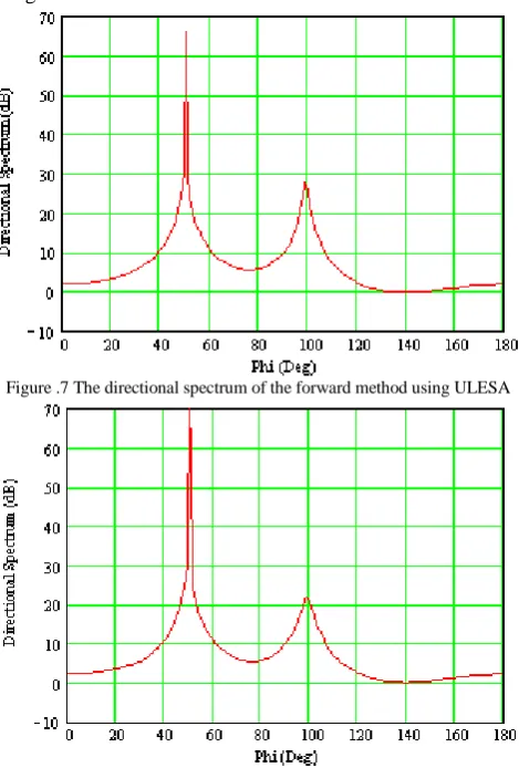
Fig.1. Consider the SOI arriving from ϕs =100oand one jammer stronger than the SOI by 47dB arriving from 500 impinging on 12 elements. Due to the use of real elements, there will be coupling effect on the performance. So, the preprocessing technique is used firstly by transforming the actual set of voltages to another set generated form ULVA of isotropic point sources.
[image:4.595.321.555.58.224.2]Fig.7, Fig.8, and Fig.9 show the performance of the forward, backward, and forward backward methods respectively for estimating the DOA of all incoming signals using ULESA
Figure .7 The directional spectrum of the forward method using ULESA
Figure.8 The directional spectrum of the backward method using ULESA
Figure.9 The directional spectrum of the forward-backward method using ULESA
The performance shown in the three figures is clear since the estimated DOA of all incoming signal coincide with actual DOA except there is a small drift by 1 deg from SOI direction for the case of forward-backward method.
B. ESLA, SCA, and SSA:
Consider an array of 12 elements is used. The elements are distributed in three different forms: Exponential Spaced Linear Array (ESLA), Semicircular Array (SCA) and Sinusoidal Spaced Array (SSA). Each element of the array is identically point loaded at the center. The elements are z-directed of length L=λ/2and placed as shown in Fig.2, Fig.3, and Fig.4 respectively.
Consider the SOI arriving from ϕs =100o and one jammer stronger than the SOI by 47dB arriving from 500 impinging on the three arrays. The preprocessing technique is used to compensate for the lack of nonuniformity in the real array contaminated by the mutual coupling effects. This is done by transforming the actual set of voltages to another set induced form ULVA of isotropic point sources consisting of 7 elements.
[image:4.595.41.276.425.772.2]Fig.10, Fig.11, and Fig.12 show the performance of the forward, backward, and forward backward methods respectively for estimating the DOA of all incoming signals using ESLA, SCA, and SSA.
[image:4.595.318.557.546.737.2]Figure.11 The directional spectrum of the backward method using ESLA, SCA, and SSA
Figure.12 The directional spectrum of the forward-backward method using ESLA, SCA, and SSA
As shown from Fig.10, Fig.11, and Fig.12, there is no great difference between the three methods for all configurations except the performance of ESLA and SCA in the backward method give a higher peak in the direction of jammer and the direction of SOI respectively.
It can be seen that the average performance of ESLA is approximately comparable with SCA and the performance of SSA is lower than ESLA and SCA.
C. Planar Array:
Consider the SOI arriving from ϕs =100o and one jammer stronger than the SOI by 47dB arriving from 500 impinging on 5×4 elements of planar array each of
2 / λ
=
L , dx =dy =λ/2 as shown in Fig.5. The elements are distributed as 5 along x-axis and 4 along y-axis. The set of voltages induced in the planar array is transformed to another set of voltages would be induced in a ULVA of isotropic point radiators along x-axis consisting of 5 elements in order to eliminate the mutual coupling between elements. This is done by using transformation matrix. The performance of three methods of antenna distribution will be investigated.
Fig.13, Fig.14, and Fig.15 show the performance of the forward, backward, and forward-backward methods
respectively for the estimation of the all incoming signals DOA using the planar array.
It is obvious from Fig.13, Fig.14, and Fig.15 that the performance of the forward-backward gives a higher peak in the SOI direction with a difference of 10 dB from the forward and the backward methods.
Figure.13 The directional spectrum of the forward method using planar array
Figure.14 The directional spectrum of the backward method using planar array
Figure.15 The directional spectrum of the forward-backward method using planar array
V. CONCLUSIONS
eliminate the coupling effect due to the use of actual elements. The performance of SSA is good but not better than ESLA, SCA, and Planar array. The average performances of ESLA, SCA, and Planar array are approximately the same. The performance of ULESA is lower than the performance of any other configuration. The reason for that is the number of elements in ULVA since the number of isotropic point radiators is always lower than the number of real elements in all configurations except ULESA.
VI. REFERENCES
[1] S. Wei, Z. P. Qian, “A Fast Estimation Algorithm Based on Direct Data Domain Least Square Approach,” ISAPE 2006- International Symposium on Antennas, Propagation and EM theory, Oct 26-29, 2006, Guilin, China.
[2] H. M. Elkamchouchi, D. A. E. Mohamed, and W. A. E. Ali. “Direct Data Domain Least Squares (D3LS) STAP Approach on Signals from Nonuniformly, Semicircular and Sinusoidal Spaced Arrays of Real Elements,” ICMMT 2010-International Conference on Microwave and Millimeter Wave Technology, May 8-11, 2010, Ghengdu, China.
[3] H. M. Elkamchouchi, D. A. E. Mohamed, and W. A. E. Ali, and M. M. M. Omar. “Space Time Adaptive Processing (STAP) using Uniformly Spaced Real Elements Based on Direct Data Domain Least Squares (D3LS) Approach,” ICMMT 2010-International Conference on Microwave and Millimeter Wave Technology, May 8-11, 2010, Ghengdu, China.
[4] Hwang, S. Burintramart, T. K. Sarkar, S. R. Best “Direction of Arrival (DOA) Estimation Using Electrically Small Tuned Dipole Antennas,” IEEE Trans. Antennas Propagat., VOL. 54, pp. 3292–3301, Nov. 2006.
[5] T.K. Sarkar, R. Adve, “Space-Time Adaptive Processing Using Circular Arrays,” IEEE Trans. Antennas Propagat., vol. 43, No. 1, Feb. 2001.
[6] T.K. Sarkar, M.C. Wicks, M. Salazar-Palma, R.J. Bonneau, Smart Antennas, Wiley, New York, 2003.
[7] H. M. Elkamchouchi, D. A. E. Mohamed, and W. A. E. Ali. “Space Time Adaptive Processing (STAP) Using Two Dimensional Array of Real Elements Based on Direct Data Domain Least Squares (D3LS) Approach,” ISSSE 2010- International Symposium on Signals, Systems and Electronics, September 17-20, 2010, Nanjing, China.
[8] S. Burintramart et al., “Performance Comparison between Statistical- based and Direct Data Domain STAPs,” Digital Signal Processing 17., pp. 737–755, 2007.
[9] T.K. Sarkar, H. Wang, S. Park, R. Adve, J. Koh, Y. Zhang, M.C. Wicks, R.D. Brown, “A deterministic approach to space-time adaptive processing(STAP),” IEEE Trans. Antennas Propagat., vol. 49, Jan. 2001.
[10]S. Burintramart, N. Yilmazer, T. K. Sarkar “Multiple Constraint Space-Time Adaptive Processing Using Direct Data Domain Least Squares (D3LS) Approach,” IEEE Trans. Antennas Propagat., vol. 48, pp. 768–771, Jan. 2007.
[11]Z. Jun, Z. ZhaoDa, Z. Tao, X. Hang, “A Modified Direct Data Domain Method in Space-time Adaptive Processing,” RAM 2008- Robotics, Automation and Mechatronics, Sep 21-24, 2008, Chengdu, China.