496
Optimization of different Parameters of a Gas
Lubricated Hydrodynamic Foil Journal Bearing for
Maximum Load Carrying capacity with Genetic
Algorithm
Mrinal Jyoti Sarma
1, Ankuran Saha
2Assam down town University1,, National Institute of Technology Agartala2, Email: [email protected]1 ,[email protected]2
Abstract-A study is done based on numerical modeling of the working of a gas lubricated hydrodynamic foil journal bearing in order to find the effects of different parameters involved in its steady state load carrying capacity. The observed results are validated with existed literature. The load carrying capacity is optimized based on the effects of those parameters using Genetic Algorithm Tool in MATLAB. The ranges of tolerance of variation of those parameters are further defined to achieve the optimized load carrying capacity.
Index Terms- Load carrying capacity; Genetic Algorithm; Gas foil bearing; MATLAB.
1. INTRODUCTION
The standard of performance and efficiency of gas foil bearing is unmatched by any conventional bearing for high speed machineries. These bearings generate a film of gas due to hydrodynamic action to withstand the load from the rotation of the shafts it supports. This modern day bearing design ensures self adjustment of the shaft miss-alignment with inherent internal damping. The foils in these bearing conform to the shape of the mating rotating shaft and provide the compliant feature of the bearing. These gas bearings can be operated at elevated temperatures since viscosity of gas increases with increase in temperature which ensures its application in wide range of operating temperatures. A typical gas foil bearing is shown in fig.1. It contains a thin layer of top foil supported on the corrugated foil. The leading edge of the bump foil is pivoted to the bearing sleeve and other end is free for providing the compliance effect. The bump foil is provided as single layered or multi-layered for varying the compliance effect of the bearing. The corrugated foils come in different configurations like bump type, leaf type, mesh type etc.
The working of the gas lubricated foil bearing is governed by the hydrodynamic action of the working fluid .Initially, when the journal starts spinning, the outer surface of the top foil remains in contact with the bump foil and inside surface with the journal. Once the rotor starts to gain sufficiently higher speeds, the foil pushed away from the journal so that there is no further contact. The separation between the journal and the foil is being maintained by the pressure generated by the rotation of the journal. Hence it becomes evident that the load bearing capacity of the gas foil bearing is dependent on the distribution of
pressure in the annular region between the shaft and the foil.
497 top foil deflection should be taken into consideration
for more reliable estimation of the bump foil bearing behavior.
Fig. 1 Schematic diagram of a gas foil bearing
It has been noted from the detailed study of the related technical papers available in the open literature that all the work that have done till now is about the evaluation of performance characteristics of the gas foil bearing considering different bearing parameters. But not much emphasis is put towards the optimized efficiency of the foil bearing with optimization of the parameters effecting it. Hence in the present work an effort has been given to find the optimized efficiency of the gas foil bearing using the GA Tool in MATLAB. Also a range of tolerance of variation of the parameters is defined within which approximately the same optimized load carrying capacity could be attained which would provide an ease of manipulating the design parameters for the design engineers in case of limited resources available.
2. NOMENCLATURE
= Angular position on the circumference of the bearing
R = Radius of the bearing C = Nominal clearance
P = Arithmetic mean pressure in the axial direction of the bearing
=Atmospheric pressure h = film thickness of the lubricant
H = Non-dimensional film thickness of the bearing = Co-efficient of viscosity of the lubricant = Bump foil deflection
=Non-dimensional bump foil thickness e =Eccentricity
=Eccentricity ratio
Α = Compliance coefficient of the bump foil material
P =Non-dimensional arithmetic mean pressure in the axial direction
= Attitude angle
= Angular velocity of the journal
i,j = Co-ordinate system used in the finite difference analysis
Ʌ = Bearing number L = Length of the bearing D = Diameter of the bearing
3. METHODOLOGY
The distribution of pressure in gas foil bearing is governed by a differential equation known as Reynolds equation. The generalized Reynolds equation for a compressible gas undergoing isothermal condition is stated as below
(
) (
)
( ) ( )
The viscosity of gas does not significantly vary with pressure, hence viscosity can be assumed to be constant.
For a perfect gas,
p= ; where R is gas constant and T is absolute temperature.
If the gas obeys the polytropic relation i.e., p* = Constant ; where n is polytropic index.
(
) ( )
( ) ( )
498 ( ) ( ) ( ) ( ) ... (1)
Now, for a steady flow process the equation further reduces to …
( ) ( )
( ) ….. (2)
The film thickness (h) varies due to the eccentricity (e) of the journal centre and bearing centre which depends on the radial load of the journal and also due to foil deflection ( ).
( ) ... (3) The bump foil deflection ( ) depends on the
compliance coefficient ( ) and average pressure across the bearing width.
( ) ... .. (4) The following substitutions are used to form the
non-dimensional Reynolds equation:
The non-dimensional Reynolds equation :
( ) ( ) ( ) ……(5) where , ( ) ( ) ( ) ... (6)
( ) ……(7) Equation (7) represents a non-dimensional form of
film thickness.
To find the pressure distribution on the journal surface a MATLAB program is written for the computational model based on the boundary conditions given bellow:
(i) P= at (ii) P= at
(iii) P= at ⁄
Here it is assumed that the initial pressure at all interior nodes as well as the nodes at the boundary of the mesh are equal to 1 atm.
3.1 Load carrying capacity
The pressure generated over the journal surface provides a load bearing component along and opposite to the load line. This load bearing component of the distributed pressure can be calculated by numerical integration.
According to the assumed co-ordinate system , the components of the load along the x and y axis could expressed as
∫ ⁄⁄ ∫
∫ ⁄⁄ ∫
2.2 Optimization of load carrying capacity
The Genetic Algorithm tool in MATLAB is used for optimization of the load carrying capacity and values for different parameters such as eccentricity ratio, compliance, angular speed etc. is determined for the optimized results. Here higher “population size” is considered during optimization for better optimized results.
A MATLAB program is further devised to define the range of tolerance of variation of different parameters for allowed optimized load bearing capacity so as to ease the design constraints for the various parameters of the bearing.
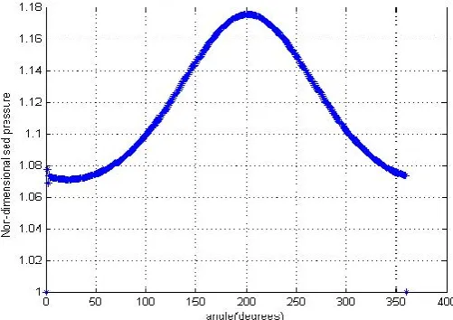
4. RESULTS AND DISCUSSIONS 4.1 Pressure distribution profile
The distributions of pressure over the journal surface at different angular positions are plotted in Fig.3 and have defined the maximum pressure region which is the region around the line of centers of the journal and
the bearing.
4.2 Film thickness profile
The fig.4 shows the variation of film thickness over different angular positions along the circumference of the bearing. From the graph between Non-dimensionalised Film thickness Vs. angular position, it has been noted that the gas film thickness gradually decreases from the inlet position reaches the minimum at the position of line of centers of the bearing and the journal and then starts gradually increasing upto a film thickness nearly equal to inlet film thickness. Hence it is also concluded that film thickness is minimum at the position where non-dimensionalised pressure is maximum.
4.3 Profile of non-dimensionalised bump foil deflection
499
pressure is minimum and maximum where the pressure is maximum. Hence the profile of non-dimensionalised bump
foil deflection with respect to pressure plotted in fig.6 is a straight line.
Fig. 2 Free body diagram of the journal
Fig. 3 Non-dimensionalised pressure vs. angular position of the bearing
[image:4.595.191.443.130.307.2] [image:4.595.193.444.385.562.2]500
Fig. 4 Non-dimensionalised film thickness vs. angular position
501
Fig. 6 Non-dimensionalised bump foil deflection Vs. Non-dimensionalised pressure
Fig. 7 Non-dimensionalised load Vs. speed of the journal
4.4 Profile of non-dimensionalised load vs. journal speed
6. OPTIMIZATION OF LOAD CARRYING CAPACITY
The plot of non-dimensional load vs. speed of the journal is shown in fig. 7. The load carrying capacity of a bearing is highly influenced by the speed of the journal. While starting a rotor supported by Air foil bearing, initially the journal slides on inside surface of the top foil until it gains a minimum speed to start the hydrodynamic action in the bearing. Hence initially the load carrying capacity is less, but with increase of speed, the load carrying capacity starts to increase up to some limit and then it shows an asymptotic behavior.
5. VALIDATION
502
Table 1. Load carrying capacity for ( ⁄ α=1)
Eccentricity Ratio(𝛆)
Compliance (α)
Attitude Angle( )
Load 0.6 0.6 0.6 1 1 1 37.12 34..41 32.1 0.5455 0.75 0.75 1 1 26.3* 0.783* 0.9 0.9 1 1 21.4 24.5 1.0867
*Heshmat et al.[3]
#Milind Babasaheb Patil et al.[2]
The optimized load carrying capacity of a hydrodynamic gas foil journal bearing is obtained (Table 3) by optimizing bearing parameters like eccentricity ratio(𝛆),compliance( ),angular speed of journal(ω), attitude angle( ) using Genetic Algorithm Tool in MATLAB.
For a short journal bearing of ⁄ , compliance=0.004, eccentricity ratio=0.597, angular speed=64374.553 and attitude angle=10.013, the optimized load carrying capacity is 3.8854
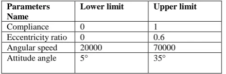
Table 2. Lower and upper limits of bearing parameters considered while optimization
Parameters Name
Lower limit Upper limit
Compliance 0 1
Eccentricity ratio 0 0.6 Angular speed 20000 70000
Attitude angle 5 35
Table 3. Optimization result for load bearing capacity of a short journal bearing (L⁄D=1 ) (Population size=50, stopping criteria (generations=100, stall generations=100))
Compli-ance (α)
Eccentri- city Ratio(𝛆)
Angular Speed in rpm( )
Attitude Angle( )
Load
0.004 0.597 64374.553 10.013 3.8854
6.1 Range of allowed tolerance of variation of bearing parameters for achieving of optimized load carrying capacity
A domain of of the bearing parameters is defined in Table 4, so as to ease the design constraints that would at least give of optimized load carrying capacity.
.
Table 4. Range of ±5% of optimized values of compliance and angular speed for eccentricity ratio=0.597,attitude angle=10.013 to achieve the optimized load carrying capacity of 3.8854 is tabulated below: Ecc-entri city ratio ( ) Attitu de angle ( ) Range of compliance ( )
Range of speed ( ) Max. Min. Max Min. 0.597 10.013 0.0043 0.00413 67500 61500 7. CONCLUSION
The optimizationof steady state load carrying capacity of a hydrodynamic gas foil bearing is done with the help of Genetic Algorithm tool in MATLAB by optimizing different bearing parameters like eccentricity ratio , compliance, angular speed, Attitude angle etc. The ranges of tolerance of variation of these parameters are also defined within which at least
[image:7.595.59.546.93.430.2] [image:7.595.66.301.103.414.2] [image:7.595.304.528.456.556.2] [image:7.595.65.298.601.678.2]503
REFERENCES
[1]Sahoo, P.( 2011) “Engineering Tribology” PHI Learning pvt. Ltd.
[2] Patil, M. B.; Kalita, K. and Kakoty, S. K. (2013): Performance Analysis of Gas Foil Bearing with Different Foil Pivot Configuration, Advances in Mechanical Engineering, Volume 2013, Article ID 843419, 9 pages.
[3] Heshmat, H. ; Walowit, J. A. ; and Pinkus, O. (1983): Analysis of gas lubricated foil journal bearings,Journal of LubricationTechnology,vol. 105, no. 4, pp. 647–655.
[4] Lee, Y.-B. ; Kim, T.-H. ; Kim, C.-H. ; Lee, N.-S. and Choi, D.-H. (2004): Dynamic characteristics of a flexible rotor system supported by a viscoelastic foil bearing (VEFB), Tribology International,vol. 37, no. 9, pp. 679–687.
[5] Lee, Y.-B. ; Park, D.-J. ; Kim, C.-H. and Kim, S.-J. (2008):Operating characteristics of the bump foil journal bearings with top foil bending phenomenon and correlation among bump foils”,Tribology International, vol. 41, no. 4, pp. 221–233.
[6] DellaCorte, C. ; Zaldana, A. R. and Radil, K. C. (2004): A systems approach to the solid lubrication of foil air bearings for oil-free turbomachinery”, Journal of Tribology, vol. 126, no. 1, pp. 200–207.
[7] Kim, D.; Lee, D. (2010): Design of three-pad hybrid air foil bearing and experimental investigation on static performance at zero running speed, Journal of Engineering for Gas Turbines and Power, vol. 132, no. 12, Article ID122504, 10 pages.
[8] Andr’es L. S. ; Kim, T. H. (2008): Forced nonlinear response of gas foil bearing supported rotors, Tribology International, vol. 41, no. 8, pp. 704–715.
[9] Kim, T. H. ;Breedlove, A.W. and Andres, L.S. (2009): Characterization of a foil bearing structure at increasing temperatures : static load and dynamic force performance, Journal of Tribology, vol. 131,no. 4, Article ID041703, 9 pages.
[10]Lee, Y.B. ; Park, D.J. ; Kim, C.H. and Kim, S.J. (2008): Operating characteristics of the bump foil journal bearings with top foil bending phenomenon and correlation among bump foils, Tribology of internationals, vol. 41, no. 4, pp. 221-233.