Volume 8, No. 5, May-June 2017
International Journal of Advanced Research in Computer Science RESEARCH PAPER
Available Online at www.ijarcs.info
Efficient Image morphing algorithm using Laplacian Pyramids
Anupama Guatam
Research Scholar Computer Science BBAU University Lucknow Uttar Pradesh India
Ram Singar Verma
Assistant Professor Computer Science BBAU University, Lucknow Uttar Pradesh India
Abstract:Image morphing has been the difficulty of a whole lot interest in latest years. It has tested to be a powerful visible consequences device in film and television, depicting the transformation of one virtual photo into any other. While this method is used successfully, the photo may be transformed into whatever a person needs with dramatic results. Morphing can be described as an animated transformation of one photo into any other photo. Morphing entails photo processing techniques like warping and move dissolving, pass dissolving manner that one photo fades to every other photograph the usage of linear interpolation. This technique is visually negative because the functions of both pictures are not aligned, and as a way to result in double exposure in misaligned areas. So as to overcome this hassle, warping is used to align the two photos earlier than cross dissolving. Warping determines the way pixels from one photo are correlated with corresponding pixels from the alternative picture. It’s far needed to map the vital pixels, else warping doesn’t paintings. Shifting other pixels is obtained by means of extrapolating the data distinctive for the manipulate pixels. In this project we implemented Laplacian Pyramid Transformation primarily based techniques of image morphing and as compared them. We tried to automate the procedure as much as possible.
Keywords: image, morphing, laplacian, pyramids
I. INTRODUCTION
Morphing is a unique effect in movement pics and animations that modifications (or morphs) one image or shape into another through a seamless transition. Most often it is used to depict one individual becoming some other through technological means or as part of a fable or surreal series.Traditionally the sort of depiction would be accomplished through pass-fading techniques on movie. Morphing algorithms preserve to develop and applications can robotically morph pictures that correspond carefully enough with exceedingly little education from the user. This has led to using morphing techniques to create convincing gradual-motion results where none existed in the authentic movie or video pictures by way of morphing among each individual frame using optical flow era. Morphing has additionally regarded as a transition technique between one scene and some other in TV suggests, although the contents of the two pics are entirely unrelated. The set of rules in this situation tries to find corresponding factors between the pics and warp one into the opposite as they crossfade at the same time as possibly less obvious as in the beyond morphing is used closely today. Whereas the effect changed into to start with a novelty, today, morphing results are most customarily designed to be seamless and invisible to the attention. Selected use for morphing consequences is modern-day virtual font design. the use of morphing era, called interpolation or more than one grasp technology, a clothier can create an intermediate between patterns, as an example producing a semi-bold font through compromising among a bold and regular style, or make bigger a fashion to create an extremely-light or extremely-bold. The technique is commonly utilized by font design studios.
II. MORPHINGPRINCIPLE
The primary principle behind picture morphing is explained on this phase. "Morphing" refers back to the mixture of generalized photo warping with a move-dissolve among
image factors. On the way to morph among pixels we outline corresponding control pixels in source photo I0 and vacation spot image I1. We then outline each intermediate frame I of the metamorphosis with the aid of creating a new set of control pixels via interpolating the manage pixels from their positions in I0 to the positions in I1. Each snap shots I0 and I1 are then warped closer to the placement of the control pixels in I. those warped photos are cross-dissolved during the metamorphosis. Consequently the distinct morphing techniques differ especially inside the way in which they carry out warping. Within the following section we can describe various image warping strategies.
III. MORPHINGTECHNIQUES
1. Mesh warping
interpolated from intermediate picture I to create destination image D.
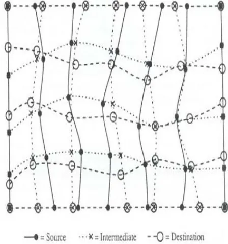
[image:2.595.47.271.79.318.2]The collection of vertical splines geared up through Sand I in the first step and with the horizontal splinesfitted throughI and D within the 2d step, are shown in the figure 1.
2. Feature based photograph Warping
This is a technique that gives an excessive stage of manage over the method. The corresponding function lines in the
photographs that are being morphed, are
interactivelydecided on. The set of rules makes use of strains to relate features inside the source image to capabilities inside the final photo. This algorithm is based totally upon fields of affect surrounding the function traces selected. It makes use of opposite mappingfor warping the image. A pair of strains (one defined relative to the source photograph, the other defined relative to the destination picture) defines a mapping from one photograph to the other (see fig. 2).
3. Thin Plate Spline based totally picture Warping
Thin-plate Spline is a conventional tool for floor interpolation over scattered records. It is an interpolation technique that unearths a "minimally bended" easy floor that passes through all given factors. The call "thin Plate" comes from the truth that a TPS extra or less simulates how a skinny metallic plate could behave if it became compelled
[image:2.595.340.559.138.231.2]via the identical manipulate points. Let us denote the target function values vi at places (xi, yi) inside the plane, with i=1,2….p , in which p is the number of function points. Specially, we will set v i identical to the coordinates (xi ’, yi’) in flip to gain one non-stop transformation for each coordinate. An assumption is made that the places (xi, yi
Fig. 3: Example of coordinate transformation using TPS.
The fig3 determines 3 an easy example of coordinate transformation the use of TPS. It begins from units of factors for which it's far assumed that the correspondences are known (a). The TPS warping permits an alignment of the points and the bending of the grid suggests the deformation needed to deliver the 2 units on pinnacle of every different (b). Inside the case of TPS implemented to coordinate transformation we truly use two splines, one forthe displacement within the x coordinate and one for the displacement in the y direction. The 2 resulting alterations are blended right into a single mapping.
) are all distinct and are not collinear.
IV.IMAGEMORPHINGALGORITHM
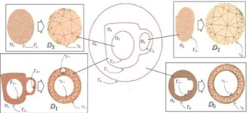
[image:2.595.49.289.527.664.2]A top level view of our morphing set of rules upon conformal welding is provided in Fig. 1, wherein we use the form con- tour with unmarried factor to demonstrate the set of rules go with the flow. Given contours (may with a couple of-connected additives), we aim to deform the enter one into the goal even as preserving the shape consistency. We generate the signature for the shape contour of the input cup, as proven in the crimson curve in Fig. 1. in addition, the signature of the goal form (the green curve in Fig. 1) can be also obtained through conformal mapping. The signatures are actual-valued periodic features of to itself, and represent the form information as given by Theorem 1. We’re able to deform the input signature to the goal one in the circle domain by using the use of the Laplace constraint, yielding the signature in blue of Fig. 1. Eventually, we reconstruct the desired form from the signature via conformal mapping. Theoretical analysis inside the preceding segment suggests that the proposed set of rules also works for shape contours with multiple-linked additives, although illustrated with the aid of pretty less difficult contours in Fig. 1. We gift a narrative of all the modules inside the manner beneath.
Fig. 1 Flowchart of our method
As a preprocessing step of our approach, we should extract the form contour of the object of interest from a given image. Contour extraction is this type of warm topic in pc vision that severa algorithms are to be had. One may additionally resort to the classical active contour (Snake) set of rules for frequent images. For pictures of rather established objects (e.g., human faces), the present day regression-based algorithms are capable of seasoned- vide fast and correct facial landmarks [9, 22, 38]. These landmarks decide the form contours to which our morphing algorithm applies. We normalize the corresponding shapes beneath translations and scaling so that we are able to express the landmark coordinates within the identical reference body. Inside the relaxation of the paper, we find the warping among contour whilst retaining shape consistence in this reference body in any other case said. We take the cup contour with complex shape con- figurations (more than one-nested components) as an instance to demonstrate the mappings that map all of the contours to a circle area Ω inside the unit disk as shown in Fig. 2. The circle domain in Fig. 2 has 3 levels and 4 components
Ωi(i=0,...,3).ThesegmentsΓipartitionthewholedomain intotheplanardomainsΩi(i=0,...,3).EachsegmentΓi
WetriangulateallΩibytheDelaunaytriangulationgiventheland marksinthecontourcomponents,andintroducetheanglestructur eintriangularmeshesinordertoperformcon- formal mapping. In the mesh, we denote vi as a vertex, [vi,vj]asanedge,and [vi,vj,vk] asaface. Theangleat vertex v
canbedeno tedastheoutercontourΓi−andtheinnerΓi+in
differentcomponentsexceptfortheoutermostoneΓ0.
i
We calculate the conformal mapping that preserves corner angles in mesh structures as detailed in [
in the triangle [vi, vj,vk] is denoted asθiki . The corner angle of the mesh is defined as the set
A(Ω) =θjki ,θijk,θkij |�vivjvk� ∈ Ω
19].
Consequently, we conformally map the planar domains, Ω0 andΩ1, to the annuli D0 with a concentric hole and 𝔻𝔻1 with multiple holes, respectively. The domains Ω2 and Ω3 are mapped to unit disks 𝔻𝔻2 and𝔻𝔻3, respectively. Γi − and Γi + (i = 1,...,3) turn into γi − and γi + by conformal mappings, and Γ0 corresponds to γ0. The results of these conformal mappings for multiple components are shown in Fig. 2.
II. Shape signatures
The important thing to our method is the derivation of shape signatures (given in Theorem 1) within the mapped area. The signatures include conformal modules and diffeomorphisms.
The conformal module of a site is determined with the aid of the configuration of the circle domain, i.e., the middle and radius of the inner circle. For the cup having four additives in Fig. 2, the middle and radius of each hollow of𝔻𝔻igives the conformal module of each component. Those facilities and radii of the holes at the plane are conformal invariants so that we can adjust picture shapes by using changing the corresponding conformal modules.
Fig. 2 Translate and scale shape components, and then apply a Riemann mapping for each domain given by shape components
Fig. 3 Construction of shape signatures
We use the outer contour of the cup Γ1as an instance to demonstrate the computation of diffeomorphisms. An identical computational procedure, detailed in Alg. 1, applies to every contour additives. Figure 2 shows
thatΓ1ismappedtoγ1−
andγ1+.Wefirstlybuildthecorrespondencebetweenpoints on γR1+and γR1−, finding the corresponding pairs (pr,ps), where pr
and ps are the points on γR1+ andγR1−
Fig. three, respectively. Sooner or later, we select a
corresponding factor pairp
shown in
randpsonγR1+andγR1−astheoriginpointssothatanypointson
γR1+andγR1−flip to perspective representations on circles.
Sooner or later, we construct the desired diffeomorphism among γR1+and γR1−
3
, a periodic real-valued function fromtoasillustratedinFig. .
The conformal module together with diffeomorphisms form the signature si
V. LAPLACIANPYRAMID
(i = 1,..., three), which generates a easy and intuitive shape illustration (centers and radii) while stopping undesired mesh systems (e.g., folding and twisting) for deformations. Hence, we're able to really exchange form contours within the parametric area via adjusting the signatures. Additionally, we can apply shape constraint to the deformation at the signature as mentioned underneath.
Photograph pyramids were defined for a multiresolution image evaluation as a model for the binocular fusion for human imaginative and prescient. A photo pyramid can be defined as collection of low or band pass copies of an authentic photograph wherein both the band restriction and sample density are reduced in ordinary steps.
The Laplacian Pyramid implements a “pattern selective” method to picture fusion, so that the composite picture is built now not a pixel at a time. The simple concept is to carry out a pyramid decomposition on every source picture, then integrate a lot of these decompositions to form a composite illustration, and ultimately reconstruct the morphed picture by way of performing an inverse pyramid transform.
[image:3.595.318.561.54.165.2]Figure 3: Schematic diagram of the Laplacian Pyramid fusion method
Laplacian Pyramid used several modes of combination, including choice or averaging. Inside the first one, the aggregate approaches selects the issue sample from the supply and copy it to the composite pyramid, while discarding the less pattern. Within the 2nd one, the technique averages the resources styles. This averaging reduces noise and gives balance in which supply photos comprise the identical sample information.
[image:4.595.52.271.57.135.2]VI.RESULTANDANALYSIS
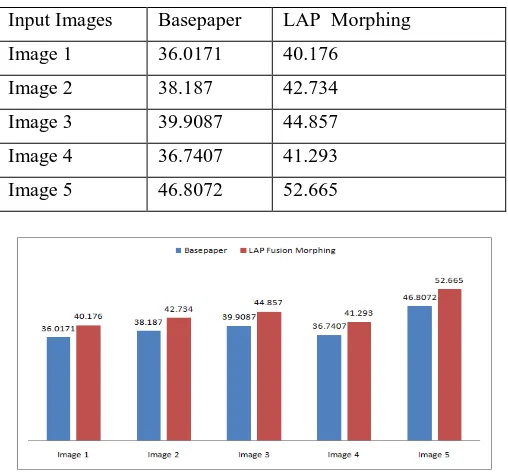
Table 1 Comparison of Peak Signal To Noise ratio for various images using basepaper and Laplacian fusion pyramids
Input Images Basepaper LAP Morphing
Image 1 36.0171 40.176
Image 2 38.187 42.734
Image 3 39.9087 44.857
Image 4 36.7407 41.293
Image 5 46.8072 52.665
[image:4.595.308.566.261.370.2]fig 1 Comparison of Peak Signal To Noise ratio for various images using basepaper and Laplacian fusion pyramids
Table 2 Comparison of SSIM for various images using basepaper and Laplacian fusion pyramids
Input Images Basepaper LAP Morphing
Image 1 0.9638 0.9756
Image 2 0.9601 0.9725
Image 3 0.9708 0.9853
Image 4 0.9743 0.9776
Image 5 0.9869 0.9968
Fig 5.2 Comparison of SSIM for various images using basepaper and Laplacian fusion pyramids
Table 5.3 Comparison of Time taken (ms) for various images using base paper and Laplacian pyramids.
Input Images Base paper LAP Morphing
Image 1 14.2479 12.82311
Image 2 13.7133 12.34197
Image 3 13.8123 12.43107
Image 4 14.319 12.8871
Image 5 22.6656 20.39904
VII. CONCLUSIONANDFUTUREWORK
Photo morphing is the system of sluggish transition among images, and has obtained a great deal interest in digital multimedia fields over decades. Morphing between two or more photos over time is a useful visual approach that generates computer graphics for educational or enjoyment purposes. Moreover, morphing can be also implemented to other fields like scientific image processing and reputation. The morphing trouble includes problems, i.e., correspondence establishments (or warping) and transition path among pix (or blending). On this paper, we focus on the correspondence issue among shapes in photos, which typically needs guide intervention. This difficulty is also essential to photograph mixing as latest tactics typically treat a photograph as a fixed of embedded curves as opposed to a grid of pixels. Specially, we address complex shapes a couple of-nested additives (e.g., human faces) displaying remarkable demanding situations to hold form consistency in morphing
As future work, further to handling extra complex occlusions, we would like to explore the complete space of color and movement paths, perhaps even allowing express consumer manage with a stroke-primarily based interface. We’d also want to bear in mind extending this technique to morphing between video sequences.
VIII.REFRENCES
[1] Ying, X. U. "Improvement of Mesh-based Image Morphing Technique [J]."Journal of Mianyang Normal University
[2] Mullens, Stephen, and Simon Notley. "Image morphing." (2008).
[image:4.595.32.286.332.569.2] [image:4.595.30.288.650.769.2][3] Nakamura, Hiroyuki, and Qiangfu Zhao. "Information hiding based on image morphing." In
[4] Potluri, Pramod, Krishna Sagiraju, and VenkatachalamTubati. "Image Morphing: Feature based, View and Mesh."
Advanced Information Networking and Applications-Workshops, 2008. AINAW 2008. 22nd International Conference on, pp. 1585-1590. IEEE, 2008.
[5] Yap, Pew-Thian, Guorong Wu, Hongtu Zhu, Weili Lin, and Dinggang Shen. "Fast tensor image morphing for elastic registration." In
Clemson University, Clemson(2009).
[6] Yap, Pew-Thian, Guorong Wu, Hongtu Zhu, Weili Lin, and Dinggang Shen. "TIMER: Tensor image morphing International Conference on Medical Image Computing and Computer-Assisted Intervention, pp. 721-729. Springer Berlin Heidelberg, 2009.
for elastic registration." NeuroImage
[7] Terada, Takuma, Takayuki Fukui, Takanori Igarashi, Keisuke Nakao, Akio Kashimoto, and Yen-Wei Chen. "Automatic facial image manipulation system and facial texture analysis." In
47, no. 2 (2009): 549-563.
[8] Cohen, Michael, and Jue Wang. "System and method for very low frame rate teleconferencing employing image morphing and cropping." U.S. Patent 7,659,920, issued February 9, 2010.
Natural Computation, 2009. ICNC'09. Fifth International Conference on, vol. 6, pp. 8-12. IEEE, 2009.