Volume 2, No. 5, Sept-Oct 2011
International Journal of Advanced Research in Computer Science
RESEARCH PAPER
Available Online at www.ijarcs.info
Design and Implementation of Red Tacton- Human Area Network
MS. Ruchi Arora*
1
Deptt. Computer Science & Engineering Baddi University of Emergimg Science & Technology,
Baddi, H.P, India [email protected]
MR. Kapil Nanda
Deptt. Electronic & Communication Engineering Haryana College of Technology & Management, Kaithal
Haryana, India [email protected]
Abstract: -Who can imagine that soon our body can be the backbone of a broadband personal data network linking our mobile phone or MP3 player to a cordless headset, our digital camera to a PC or printer, and all gadgets one carries around to each other? This Can be achieved by using your body to create a high-speed computer network called Red Tacton-Human Area Network (HAN). In this paper we design and implemented Red Tacton by using VHDL a hardware descriptive language which describes the behavior of Electronic Circuit. Two way communications is also achieved by using Red Tacton
Keywords:transmitter,receiver,electricfield,communication
I. INTRODAUCTION
Red Tacton is a new era human networking technology that uses the surface of the human body as a safe, high speed network transmission path. Red Tacton uses the minute electric field emitted on the surface of the human body. Technically, it is completely distinct from wireless and infrared. A transmission path is formed at the moment a part of the human body comes in contact with a Red Tacton transceiver. Physically separating ends the contact and thus ends communication.[2] Using Red Tacton, communication starts when terminals carried by the user or embedded in devices are linked in various combinations according to the user's natural, physical movements. Communication is possible using any body surfaces, such as the hands, fingers, arms, feet, face, and legs. Red Tacton works through shoes and clothing as well.[5]
A. How Red Tacton Works?
a. Using a new super-sensitive photonic electric field sensor, Red Tacton can achieve duplex communication over the human body at a maximum speed of 10 Mbps.
Figure.1: Basic Working Principle of Red Tacton
b. 2. The Red Tacton transmitter induces a weak electric field on the surface of the body.
c. The Red Tacton receiver senses changes in the weak electric field on the surface of the body caused by the transmitter
d. Red Tacton relies upon the principle that the optical properties of an electro-optic crystal can vary according to the changes of a weak electric field.[4]
Red Tacton detects changes in the optical properties of an electro-optic crystal using a laser and converts the result to an electrical signal in an optical receiver circuit.
B. Mechanism of Communication with Red Tacton: a. The transmitter sends data by inducing fluctuations in the
[image:1.612.42.279.503.698.2]minute electric field on the surface of the human body. Data is received using a photonic electric field sensor that combines an electro-optic crystal and a laser light to detect fluctuations in the minute electric field.
Figure. 2: Mechanism of Red Tacton
b. 2. The naturally occurring electric field induced on the surface of the human body dissipates into the earth. Therefore, this electric field is exceptionally faint and unstable.
Figure. 3: Data Flow in Red Tacton
C. Operating Principle of Red Tacton:
1. The operating principle is illustrated in fig. 2. The electric field induced toward the body by the transmitter‟s signal electrode is represented by Ea. The system requires a ground close to the transmitter signal electrode, so electric field Eb induced from the body can follow a return path to the transmitter ground. Moreover, since people are usually standing on a floor or the ground, electric field Ec escapes from the body to ground, mainly from the feet. The electric field Es that reaches the receiver is Es = Ea – (Eb + Ec). It couples to the electro-optic crystal and changes the crystal‟s optical properties. This change is detected by laser light and transformed into digital data by a detector circuit.[3]
a. Red Tacton Transceiver:
Figure 1shows a photograph of the RedTacton transceiver connected to a PDA and a block diagram of the Red-Tacton transceiver developed by NTT. The transmitter consists of a transmitter circuit that induces electric fields toward the body and a data sense circuit, which distinguishes transmitting and receiving modes by detecting both transmission and reception data and outputs control signals corresponding to the two modes to enable two-way communication. Implementation of a receive-first half-duplex communication scheme that sends only after checking to make sure that there is no data to receive in order to avoid packet collisions between terminals in compliance with the protocol.
The receiver consists of an electro-optic sensor and a detector circuit that amplifies the minute incoming signal from the electro optic sensor and converts it to electrical signal. NTT conducted a series of trials in which data was sent through human bodies using Red Tacton transceivers.[7]
D. Introduction to VHDL:
VHDL is a hardware description language. It describes the behaviour of an electronic circuit, from which the physical circuit can then be attained. VHDL stands for VHSIC hardware description language. VHSIC stands for very high speed integrated circuits, and initiative funded by the United States department of defence in the 1980”s that led to creation of VHDL. Its first version was VHDl87, later upgraded to the so called VHDL 93. VHDL was the original and first hardware description language to be standardized by the institute of electrical and electronics engineers, through the IEEE 1076 standard. An additional standard, the IEEE 1164,
[image:2.612.371.524.98.276.2]was later added to logic system. VHDL is intended for circuit synthesis as well as circuit simulation.
Figure. 4: VHDL Design Flow Chart
II. DESIGN AND IMPLEMENTATION
A. Design of Red Tacton:
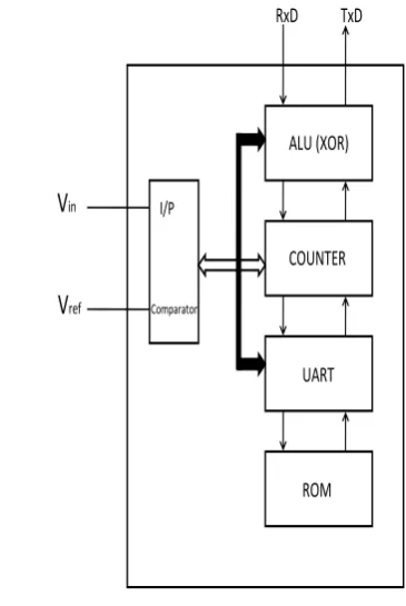
The idea of Red Tacton can be developed with the help of VHDL. We firstly make equivalent block diagram of Red tacton and concept behind individual block will be developed in VHDL and simulte with the help of XILINX. The basic block diagram to implement the concept of design of Red Tacton chip is:
RxD TxD
Comparator
ALU (XOR)
COUNTER
UART
ROM
V
inV
ref [image:2.612.329.512.431.704.2]I/P
a. Comparator:
In Electronics, a comparator is a device which compares two voltages or currents and switches its output to indicate which is larger. A dedicated voltage comparator will generally be faster than a general-purpose op-amp pressed into service as a comparator.[6] Here, we will be referring the body field to trigger the Transmission/Reception by the help of comparator which is given a reference voltage of 25mV equal to human body electric field. Comparing the two we will get a Logic High to trigger UART.[3]
b. UART:
A universal asynchronous receiver/transmitter (usually abbreviated UART) is a type of "asynchronous receiver/transmitter", a piece of computer hardware that translates data between parallel and serial forms.[7] UARTs are commonly used in conjunction with other communication standards such as RS-232. Here, after getting logic high from comparator UART starts transmitting the data from ROM. The protocol we are following in the UART section is: “0” as Start Bit, “1” as Stop Bit and 8-Bit as a data Total no of Bits Transmitted = 1+8+1=10 bits
c. Counter:
The no. of bits transmitted can be counted by the Counter section. When the direction is 1 it counts in up direction and when the direction is 0 it counts in down direction. In this we are using logic 7 down to 0 means it can count bits 0-255.The data in memory is stored in the form of bits and picked by UART the number of bits that are to be transmitted is counted by the counter.
ALU: Arithmetic and Logic Unit
We can perform many arithmetic and logic functions with the help of ALU. Here we are using ALU as Parity Checker using XOR logic.[8]
B. Implementation of Red Tacton:
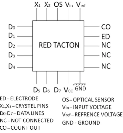
[image:3.612.331.534.60.280.2]By using VHDL Language we have made logical design of Red Tacton chip. By connecting comparator, ROM, UART, Counter and Parity Counter using programming we have developed the logic for data transmission and reception from one Transciver Red Tacton Chip to another Transciver Red Tacton Chip at the speed of 8Mbps. In this case, we declared the entity named “RED” in which we are declaring the signals and ports that are clk, hand_shake, Vin, sdo and sdi. These five signals will be connected to the external world.[10]The clk will be connected to crystal and body field, as we have told earlier, will be act as a Vin. The sdi pin will be connected to flash memory in which data is stored and the sdo is connected to count out. Hand_shake signal will be connected to the selector switch. These signals can be connected to the pins of FPGA, assinged the nos to pins by burning the program in FPGA kit through 25 pin interface which connects the PC & FPGA kit and then it will behave as a transciver.[9] The transmission and reception of data will be depending upon the status of selector switch which will be assigned by us. The FPGA chip will be look like as shown in Fig. 6.[2]
Figure 6: Red Tacton Chip
The internal connections of the program named red are declared in architcture using the mixed modling i.e. structural and behavioral. Here we are using two components: tx & rx and signals hand_shake, vref, parity, data_st, data_st1, data_st2, data_tx1, data_tx2, data_tx3, count, hand_t and hand_t1. The value of signal vref is 25mV because the value of body electric field is 25mV (00100101). The signal parity is assinged value “00000000” and all the data bits that are to be transmitted or received from or by the chip are XORing with this parity signal. Data_st is used to store the bits that are assigned in signals data_tx1. The bits assigned in data_tx1 are 01010010 which is the ASCII code of "R”. Data_st1 is used to store the bits that are assigned in signals data_tx2.[5] The bits assigned in data_tx2 are 01000101 which is the ASCII code of "E”. Data_st2 is used to store the bits that are assigned in signals data_tx3. The bits assigned in data_tx3 are 01000100 which is the ASCII code of "D”.
The status of hand_shake and hand_shake1will decide the mode of chip whether it will act as transmitter or receiver. In this case, when hand_shake is equals to 1 and hand_shake1 is equal to 0 then chip will act as transmitter and receiver respectively and vice-versa. After 30th clock the data transmission will be stopped.[8]
III. RESULTSANDDISCUSSION
In this case, we are using XILINX software version 8.1 with modal simulator. In our program there is an IEEE library which contains all the header files of my program means all the functions and keywords. Our library contains different packages like IEEE.STD_LOGIC_1164, IEEE.STD_LOGIC_ARITH,
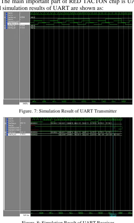
The main important part of RED TACTON chip is UART and simulation results of UART are shown as:
Figure. 7: Simulation Result of UART Transmitter
Figure. 8: Simulation Result of UART Receiver
Here we transmitted and received the word “RED” using Red Tacton chip.
The protocol we are following in the UART section is of our program:
“0” as Start Bit, “1” as Stop Bit and 8-Bits as a data Total no of Bits Transmitted = 1+8+1=10 bits
[image:4.612.49.272.58.429.2]In this case, we are transmitting “r” , “e” and “d” therefore the total bits that are to be tranferred according to our protocol are 30 (8*3 + 6=30) and these 30 bits are count by counter and displayed by UART section.
Figure. 9: Simulation Results of Red Tacton Transmitter to Transmit word „RED‟
Figure.10: Simulation Results of Red Tacton Receiver to Receive word „RED‟
IV. CONCLUSION AND FUTURE WORK
Red Tacton
is an exciting new technology for
human area networking. Development of a transceiver that uses the human body as a data transmission medium based on an electric-field sensor that uses an electro-optic crystal and laser light.[5] Using this transceiver, we can succeed in achieving communication in accordance with IEEE 802.3 through a human body from one hand to the other hand. While the objective is to implement RedTacton system supporting two-way intra body communication at a rate of 10 Mbit/s between any two points on the body, in the long run include development of a mass-market transceiver interface supporting PDAs and notebook computers while continuing efforts to reduce the size and power consumption of the transceiver to enhance its portability.[9]
The physical design of Red Tacton chip can be done by implementing the logical design i.e. pre layout simulation to the post layout simulation and circuit extraction. By using the FPGA or CPLD chip depending on our requirement i.e. whether we require the program storage in RAM or EEPROM and then by using wafer fabrication, pattern making, die extracting or circuit extraction using blocks of logical cells in the net lists and plastic packaging by burning the whole program in the permanent silicon wafer and connect all the ports as mentioned in program given above to the external world.
V. REFERENCES
[1]. T. G. Zimmerman, “Personal Area Networks: Near-field intrabody communication,” IBM Systems Journal, Vol. 35, Nos. 3&4, pp. 609-617, 1996.
[2]. T. Nagatsuma and M. Shinagawa, “Photonic measurement technologies for high- frequency electronics,” NTT REVIEW, Vol. 14, No. 6, pp. 12-24, 2002.
[3]. M. Shinagawa, “Development of Electro-optic Sensors for Intra-bodyCommunication,” NTT Technical Review, Vol. 2, No. 2, pp. 6-11,2004
[image:4.612.50.274.553.700.2]based on the electro-optic effect,” IEEE Trans. IM, Vol. 53, No. 6, pp. 1533-1538, 2004.
[5]. http://www.arib.or.jp/english/html/overview/st_j.html
[6]. M. Mizoguchi, T. Okimura, and A. Matsuda, “Comprehensive Commercialization Functions,” NTT Technical Review, Vol. 3, No. 5, pp.
[7]. 1. Electric Field near human body:- jap.physiology.org/cgi/reprint/26/6/838.pdf
2. Intensity of Electric field: - doi.wiley.com/10.1002/eej.4391030611
[8]. T. Nagatsuma and M. Shinagawa, “Photonic measurement technologies for high-frequency electronics,” NTT REVIEW, Vol. 14, No. 6, pp. 12-24, 2002.
[9]. M. Shinagawa, “Development of Electro-optic
Sensors for Intra-body Communication,” NTT Technical Review, Vol. 2, No. 2, pp. 6-11, 2004. http://www.redtacton.com/
[10]. M. Shinagawa, M. Fukumoto, K. Ochiai, and H. Kyuragi, “A nearfield- sensing transceiver for intra-body communication based on the electro-optic effect,”