Strain Measurement Using Phase-shifting Digital Holography
with Two Cameras
M. Fujigaki1,a, R. Nishitani2, Y. Morimoto3
1Department of Opto-mechatronics, Faculty of Systems Engineering, Wakayama University,
Sakaedani 930, Wakayama, Japan
2 Graduate School of Systems Engineering, Wakayama University, Sakaedani 930, Wakayama,
Japan
3Moire Institute Inc., Hagurazaki 2-1-4-804, Izumisano, Osaka, Japan
Abstract. Phase-shifting digital holography is a convenient method to measure displacement and strain distributions. Development of compact and conventional strain distribution measurement equipment for practical use is required for inspection of health monitoring and life lengthening of infrastructures such as steel bridges. In this paper, we propose an off-axis reconstruction method for displacement and strain distribution measurement with a phase-shifting digital holography. In the case of off-axis optical setup, the pitch of the fringe appearing on the image sensor becomes smaller than a pixel size. However, the phase-shifting digital hologram can be obtained even if the off-axis setup and effective results can be obtained using a Windowed-PSDHI. The principle and the experimental result of strain distribution measurement was performed with this method using two cameras.
1 Introduction
Development of compact and conventional strain distribution measurement equipment for practical use is required for inspection of health monitoring and life lengthening of infrastructures such as steel bridges.
Phase-shifting digital holography[1] is a convenient method to measure displacement and strain distributions on the surface of an object. Many researchers are studying this method and several compact equipments are developed[2]. We also developed compact equipments for strain measurement[3]. In these equipments, several object waves are necessary to measure the in-plane displacement and strain distribution. To simplify the optical setup is required for producing more compact equipment. In this paper, strain distribution measurement using two cameras with phase-shifting digital holography is proposed.
2 Phase-shifted digital hologram on off-axis optical setup
ae-mail : fujigaki@sys.wakayama-u.ac.jp
© Owned by the authors, published by EDP Sciences, 2010 DOI:10.1051/epjconf/20100630001
2.1 Principle of phase-shifting digital holography
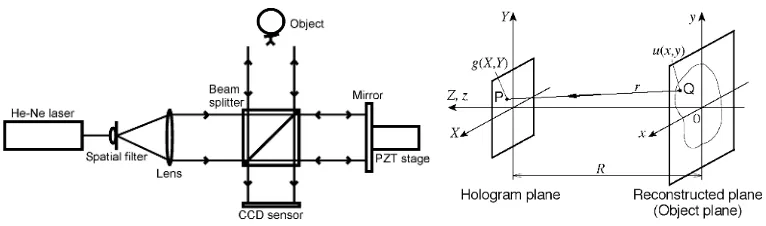
A Twyman-Green type interferometer used in this study is shown in Fig. 1. Collimated light from a laser is divided into an object wave and a reference wave by a beam splitter. The phase of the reference wave, α, is shifted by a PZT stage. The value α is set to 0, π/2, π and 3π/2 in this phase-shifting digital holography. The four phase-shifted digital holograms are recorded on the CCD plane in a CCD camera without any focusing lens. The intensity of the hologram with a phase-shift value α
at the pixel coordinates (X, Y) on the CCD plane is expressed as I(X, Y, α). The amplitude a0(X, Y),
the phase Φ0(X, Y) and the complex amplitude g(X, Y) of the object wave are expressed at the pixel
coordinates (X, Y) on the CCD plane as follows, respectively.
€
a0(X,Y)=
1
4 I(X,Y, 3π
2 )−I(X,Y, π 2) 2
+
{
I(X,Y,0)−I(X,Y,π)}
2 (1)€
tanΦ0(X,Y)=
I(X,Y,3π
2 )−I(X,Y, π
2)
I(X,Y, 0)−I(X,Y,π) (2)
€
g(X,Y)=a0(X,Y)exp (
{
iΦ0(X,Y)}
(3)By calculating the Fresnel diffraction integral from the complex amplitudes g(X, Y) on the CCD plane (hologram plane), the complex amplitude u(x, y) of the reconstructed image at the position (x,
y) on the reconstructed object surface at the distance R from the hologram plane is expressed as follows.
€
u(x,y)=exp ik(x 2
+y2) 2R
F exp ik(X 2
+Y2) 2R
g(X,Y)
(4)
where k and F denote the wave number of the light and the operator of Fourier transform, respectively. R is called as a reconstruction distance. A conception diagram of diffraction is shown in Fig. 2. The optical axis is normal to the hologram plane and the origin goes through the center of the hologram plane. By calculating the intensities of these complex amplitudes on the reconstructed object surface, a holographic reconstructed image is obtained.
2.2 Phase-shifted digital hologram on off-axis optical setup
In general, an object beam and a reference beam should be on-axis in a digital holography. The off-axis optical system makes it easy to produce a deformation measurement system using an object beam and multiple imaging devices such as a CCD. Reducing a number of object beams simplifies the optical setup.
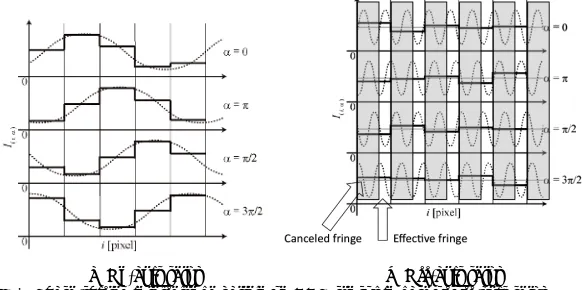
Figure 3(a) and (b) show schematic phase-shifted interference patterns on CCD sensor in a case of on-axis and off-axis optical setup, respectively. The pitch of the fringe appearing on the CCD sensor becomes larger than a pixel size in the case of on-axis optical setup. So, the phase-shifted fringe pattern can be appear clearly. On the other hand, the pitch of the fringe appearing on the CCD sensor becomes smaller than a pixel size in the case of off-axis optical setup. The part of the integer pitches of fringe appearing on a pixel is canceled. As the remaining part is not canceled, the phase-shifting digital hologram can be obtained even if the off-axis setup.
(a) On-axis setup (b) Off-axis setup Fig. 3. Phase-shifted interference pattern on CCD sensor in case of off-axis setup
3 Displacement and strain measurement using two CCD cameras
Figure 4 shows an off-axis optical setup for displacement and strain measurement using two CCD sensors and the reconstructed images, respectively. A collimated object wave is illuminated onto an object from the front of an object. The two sensors are placed beside the incident object wave. The directions of the optical axes of the sensors are parallel with the incident object beam. The object waves scattered on the surface of the object reach sensor 1 and sensor 2 with angles of θ1 and θ2, respectively.
In the case of CCD sensor 1, digital holograms produced with the scattered object wave and a reference wave, which comes to the sensor perpendicularly, can be obtained. The reconstructed image of the object appears in front of sensor 1. Phase difference Δφ1 can be obtained from the reconstructed image before and after deformation. In the same way, phase difference Δφ2 can be obtained from the reconstructed image appearing in front of sensor 2. In-plane displacement for the
x-direction, dx and the out-of-plane displacement for the z-direction, dz are calculated by Eq. (1) and
(2), respectively, where l is the wavelength.
€
dx=
λ 2π⋅
(cosθ2+ 1)Δφ1−(cosθ1+ 1)Δφ2
(cosθ2+ 1)sinθ1+(cosθ1+ 1)sinθ2 (5)
dz= λ
2π⋅
sinθ2Δφ1−sinθ1Δφ2
(cosθ1+ 1)sinθ2+(cosθ2+ 1)sinθ1
Strain distribution εx for the x-direction can be obtained by differentiation of the displacement dx for the x-direction as shown in Eq. (7).
€
εx= ∂dx
∂x =
λ
2π⋅
(cosθ2+ 1)∂Δφ1
∂x −(cosθ1+ 1)
∂Δφ2
∂x
(cosθ2+ 1)sinθ1+(cosθ1+ 1)sinθ2
(7)
In this method, the position of the reconstructed image of the object in each reconstructed image taken by two CCD sensors should be the same. It is, however, difficult to adjust the position of the CCD sensors accurately. In this method, a method to produce a shifted reconstructed image using the feature of Fourier transform is used. The reconstructed image can be shifted easily on the reconstructed image by shifting the digital hologram as shown in Fig. 5. The shifting resolution on the reconstructed image depends on the pixel size on the CCD sensor.
Fig. 4. Off-axis setup for displacement distribution Fig. 5. Shift of reconstructed image
measurement using two CCD sensors using Fourier transform
4 Experiment for displacement and strain distribution measurement
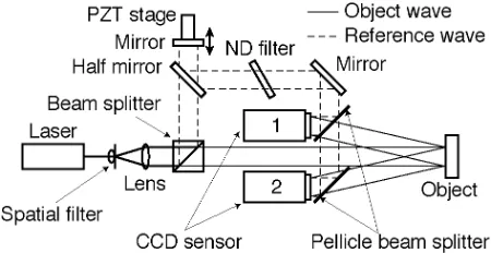
Figure 6 shows an experimental setup for displacement and strain distribution measurement using two CCD sensors. The pixel size of the CCD sensors is 4.65 µm x 4.65 µm. Reference waves reach the CCD sensors through the path shown as broken lines. The phase can be shifted by a mirror placed on a PZT stage. An object beam irradiates an object with an incident angle of 0 degree. The object beam scattered on the object are recorded as digital holograms on the CCD sensors. The reconstructed length is 300 mm. The angles of θ1 and θ2 are 7.59 degrees and 6.94 degrees, respectively.
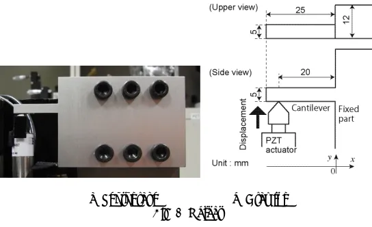
(a) Photograph (b) Drawing Fig. 7. Object
A cantilever as shown in Fig. 7 is used as the object. The material is anodized aluminium. The part near the free end (x = -20 mm) is displaced with 12 mm for the y-direction by a PZT actuator.
Figure 8 and Fig. 9 show reconstructed images obtained from both the sensor 1 and the sensor 2 before and after deformation, respectively. The analyzed image size is 960 pixels x 960 pixels. These images are reconstructed as the object is located in front of the CCD sensors. Minor adjustment of the position between the reconstructed image obtained from CCD sensor 1 and CCD sensor 2 is performed with moving the center position of the hologram with the method using Fourier transform[4]. The area size of the reconstructed image is 40.8 mm x 40.8 mm.
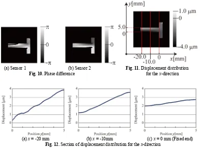
The phase differences obtained from Fig. 8 and Fig. 9 are shown in Fig. 10. These phase differences are obtained by Windowed PSDHI[5] for reducing speckle noise. The displacement distribution for the x-direction shown in Fig. 11 is obtained from Fig. 10 using the Eq. (5). Figure 12(a), (b) and (c) show sections of the displacement distribution for the x-direction at x = -20 mm, x = -10mm and x = 0 mm, respectively. The sectional positions are shown as red lines on Fig. 11.
The strain distribution for the x-direction shown in Fig. 13 is obtained from Fig. 11 with spatial differentiation for the x-direction using the Eq. (7). Positive and negative strain appear at the lower and upper sides near the fixed end of the cantilever, respectively.
5 Conclusions
We proposed a strain distribution measurement using two cameras with phase-shifting digital holography. This method uses an off-axis reconstruction method. An experiment of displacement and strain distribution measurement was performed with this method. This method can be applied to develop a compact equipment for strain measurement.
(a) Sensor 1 (b) Sensor 2 (a) Sensor 1 (b) Sensor 2
Fig. 8. Reconstructed images Fig. 9. Reconstructed images
(a) Sensor 1 (b) Sensor 2 Fig. 11. Displacement distribution
Fig. 10. Phase difference for the x-direction
(a) x = -20 mm (b) x = -10mm (c) x = 0 mm (Fixed end)
Fig. 12. Section of displacement distribution for the x-direction
Fig. 13. Strain distribution for the x-direction
References
1. I. Yamaguchi, and T. Zhang, Optics Letters, 22-16, 1268-1270 (1997)
2. M. Kujawinska, A. Michalkiewicz, Proceedings of the International Symposium to Commemorate the 60th Anniversary of the Invention of Holography, 81-88 (2008)
3. M. Fujigaki, R. Kido, K. Shiotani, Y. Morimoto, Proceedings of the International Symposium to Commemorate the 60th Anniversary of the Invention of Holography, 316-323 (2008)
4. Matsui, A., Fujigaki, M., Morimoto, Y. and Matui, T., Optical Axis Adjustment Method by Software in Multi Beam Phase-shifting Digital Holography. Proceedings of 11th Intelligence Mechatronics Workshop (in Japanese), 10-13(2006)