J.Felix1,,G. J.Rodriguez1,
1Laboratorio de Partículas Elementales. División de Ciencias e Ingenierías, Campus León, Universidad de Guanajuato
Abstract.Multiwire proportional chamber is a conventional technique to study radiation in general, and cosmic rays in particular. To study cosmic rays, it was planned, designed, constructed, characterized, and tested a four channel mini wire chamber, based on two 3 cm×3 cm×0.6 cm Aluminum frames, two 3 cm×3 cm×0.6 cm plastic frames, two 3 cm×3 cm×0.3 cm Aluminum frames, two electronic planes each with two Tungsten Gold plated 1 mil diameter wires, parallel and 1 cm apart each other at 25 g stretched -each plane was 90o rotated each other in the final assemble- and two Aluminum foil window to define the gas volume; it was operated with Argon 90%-CH4 10% gas mixture at 1 atmosphere and ambient temperature (20oC in the average). It is presented technical details, results on characterization, and preliminary results on cosmic rays detection.
1 Introduction
To detect cosmic rays, and radiation in general, there are multiwire proportional chambers, parallel plate chambers, resistive plate chambers, etc. used in high energy physics, nuclear physic, etc. to de-tect particles or radiation in general [1] with applications in medicine, archeology, biology, planetary science, integrated-circuit quality control, geology, environmental science, volcanology, climatology, security, and many other applications. All of them are based on especial gas systems and applied high voltages [2-18].
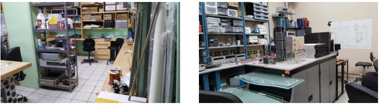
Here in Mexico, Universidad de Guanajuato, Guanajuato, there is the Laboratorio de Partículas Elementales, División de Ciencias e Ingenierías (DCeI), Campus León (CL), Universidad de Gua-najuato (UGTO) a small facility to design, construct, test, and run small ionizing particle detectors, specially, cosmic ray detectors. See Figure 1. http://laboratoriodeparticulaselementales.blogspot.mx/.
There are many projects. One of them is related with design construction and operation of a four channel mini wire chamber to study very fast cosmic ray signals and apply cosmic rays to a broad technological areas –oil and mineral exploration, etc.- and basic science research –biology, particle physics, etc.-. But the applications are, and overall, for research, for teaching and for learning physics. These series of experiences could lead to propose a big cosmic ray detector of about 40 000 detection channels, with particle trajectory reconstruction and particle identification capabilities to study very fast cosmic ray signals.
e-mail: [email protected]
Figure 1.Different views of Laboratorio de Partículas Elementales, DCeI. CL. Universidad de Guanajuato. Left, construction area; right, electronic testing area.
2 Design and construction
A layout of the 4 channel mini wire chamber is in Figure 2, left, performed with Sketchup (https : //www.sketchup.com/). This detector is based on two homemade electronic boards, Figure 2, right.
It contains the basic electric and electronic circuitries to operate, readout, and transmit the digital information. It is intended to detect ionizing radiation in general and cosmic rays in particular. It is our own invention, design and construction.
Figure 2. Left, layout of the planned mini four wire chamber. Main components –electronic boards and Alu-minum frames- are shown. Right, electronic boards; the basic electronic circuit is shown.
The detector electronic board is 4 cm×11.5 cm×1 mm, with a 3 cm×3 cm square hollow, as is shown in Figure 2; with two channels each, based on Tungsten 2.54×10⁻³ cm in diameter, gold-plated, from California Fine Wires (http://www.cal f inewire.com/index.html), separated each other by one cm, stretched by 25 g, and soldered to the electronic board. Each board has the HV connector and the RC circuit, see Figure 3, left.The detection regions are defined by the crossing wires,Ri j, i,j=1,2,3, see Figure 3, right.
Each electronic board was placed 90oeach other, with one above and other below rubber 4 cm×4 cm×0.6 cm square, with a symmetrical 3 cm×3 cm square hollow. Figure 4, left. This system was supported by two 4 cm×4 cm×0.6 cm Aluminum frames with a symmetrical 3 cm×3 cm square hollow, one for below and one for above, and closed with two tops, one above and one below. Figure 4, right.
The completed system was assembled by 4 screws 1
8 inch diameter. A gas chamber was formed with this stack, with one1
Figure 1.Different views of Laboratorio de Partículas Elementales, DCeI. CL. Universidad de Guanajuato. Left, construction area; right, electronic testing area.
2 Design and construction
A layout of the 4 channel mini wire chamber is in Figure 2, left, performed with Sketchup (https : //www.sketchup.com/). This detector is based on two homemade electronic boards, Figure 2, right.
It contains the basic electric and electronic circuitries to operate, readout, and transmit the digital information. It is intended to detect ionizing radiation in general and cosmic rays in particular. It is our own invention, design and construction.
Figure 2. Left, layout of the planned mini four wire chamber. Main components –electronic boards and Alu-minum frames- are shown. Right, electronic boards; the basic electronic circuit is shown.
The detector electronic board is 4 cm×11.5 cm×1 mm, with a 3 cm×3 cm square hollow, as is shown in Figure 2; with two channels each, based on Tungsten 2.54×10⁻³cm in diameter, gold-plated, from California Fine Wires (http://www.cal f inewire.com/index.html), separated each other by one cm, stretched by 25 g, and soldered to the electronic board. Each board has the HV connector and the RC circuit, see Figure 3, left.The detection regions are defined by the crossing wires,Ri j, i,j=1,2,3, see Figure 3, right.
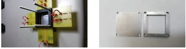
Each electronic board was placed 90oeach other, with one above and other below rubber 4 cm×4 cm×0.6 cm square, with a symmetrical 3 cm×3 cm square hollow. Figure 4, left. This system was supported by two 4 cm×4 cm×0.6 cm Aluminum frames with a symmetrical 3 cm×3 cm square hollow, one for below and one for above, and closed with two tops, one above and one below. Figure 4, right.
The completed system was assembled by 4 screws 1
8 inch diameter. A gas chamber was formed with this stack, with one1
8 in input plastic elbow pipe and 18in output plastic elbow pipe, to circulate,
Figure 3. Left, the basic electronic circuit to readout the electric signal leaved by the passage of the ionizing particle. Right in this draw, A1, A2, B1, B2 represent the four channels. With A1 and A2 are represented one electronic board; with B1, B2 are represented the other electronic board. The 9 detection regions (Ri j;
i,j=1,2,3) are shown.
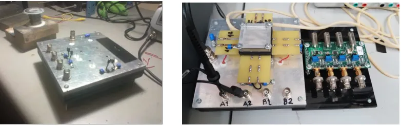
take in and take out Ar90%+CH410% commercial gas. See Figure 5, left. The complete four channel mini wire chamber is in Figure 5, right.
The flow of gas was regulated by a glass bubbler constructed for this purpose and operated with mineral cosmetic oil. See Figure 6, left. The analogical signal was digitalized by an additional electronic board designed and constructed for this purpose, see Figure 6, right.
The whole system was assembled and supported by an Aluminum base to connect electrically the four channels and readout the analogical signals, and attach the digital circuit. See Figure 7, left. Final assembling is in Figure 7, right. Many details can be seen, especially the cross disposition or the two electronic boards, 90oone with respect to the other, the gas pipes.
Figure 4.Left, rubber square seals. Right, Aluminum detector top and Aluminum frame.
3 Experimental Setup
The four wire channel detector, the digitalizing electronic board, the high voltage power supplier, the gas system –gas bubbler and gas container-, and one oscilloscope, or the data acquisition system were assembled to operate together. See Figures 8-10.
The four wire channel detector, the digitalizing electronic board, and the gas bubbler were home made. High voltage power supplier is a KEITHEY 2290-2 5 kV or a Home made or a POWER DESIGNS INC. Palo Alto California Model 1570; the oscilloscope is a Tektronics TDS 1001 C-EDU, or a GW INSTEK GDS-3354; and the data acquisition system is a 32 channel Compact Rio from National Instruments (http://www.ni.com/compactrio/). Figure 11.
Figure 5.Left, mini four wire chamber, basic elements are shown, specially the plastic sealers. Right, completed assembled.
Figure 6.Left, home made gas bubbler operated with cosmetic oil. Right four channel digitizer electronic circuit.
Figure 7. Left,this is the base for the mini four channel chamber and its electronic boards. Right, home made mini four wire chamber is shown; many details can be seen.
20oC. The conditions were not ideal. Some contaminants are present like the following: dust, water vapor, temperature fluctuations and electric noise.
Figure 8.One experimental setup. Power suppliers, multimeter, and oscilloscope. Displays on the oscilloscopes are seen.
Figure 10.Another experimental setup. Many details are shown.
Figure 11.Data Acquisition system. Compact RIO from National Instruments surrounded by other instruments.
4 Characterization
Figure 10.Another experimental setup. Many details are shown.
Figure 11.Data Acquisition system. Compact RIO from National Instruments surrounded by other instruments.
4 Characterization
The four wire chamber was purged and cleaned by running Ar90%-CH410% gas, for ten hours, at 3 cm of oil above the normal atmospheric pressure. After that, the electrical tests and detections test
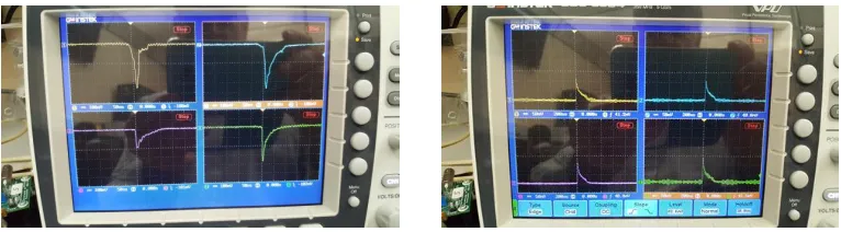
Exponential decay, and exponential crescent, signals were injected to the four wire channel detector using a Tektronic oscillator, with frequencies between 0 Hz and 1 MHz, 1 Vpp. The detector was operated at 0.0 Vcd, during these tests. The four wire channel detector works properly with negative and positive signals; both, digital and analogical signal electronic circuits are 100 % efficient, at least inside the frequencies where it was operated, and work properly. The electronic noise is of the order or 20 mVpp. It is from the ambient, and from the power suppliers. The discriminator trigger was fixed at 3 times the noise level, about 60 mV cd. Attenuation factor is about 50 %, the output signal is about one half of the input signal, from 1 Hz up to 1 MHz. Cross talk signals were observed; they were eliminated with a 100 Ohm electrical resistor at the input, in series with the metallic fiber detector.
Figure 12.Left, signals obtained with positive high voltage. Right, signals with negative high voltage. They are slower compared with those from positive high voltage.
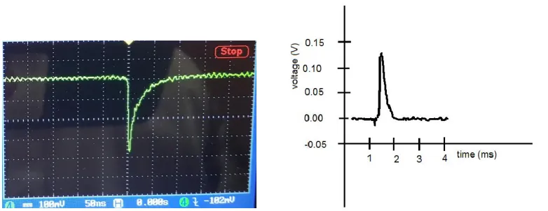
Figure 14.Left, pulse from the mini four channel chamber compared with right pulse from Z. Ahmed et al, IOP Publishing Ltd and Sissa Medialab srl. Doi: 10.1088/1748-0221/9/01/P01009.
5 Results
The amplitudes of signals are of the order of 300 mV, but are variables; they are related with the energy cosmic particles deposit on the gas chamber. The average amplitude depends on the applied high voltage close to linearly, for both negative and positive voltages. The observed rise time is about 5 ns; the decay time, about 20 ns. See Figure 14. There is a comparison with signal from reference [19]. It is seen that this four wire chamber is faster than others, which makes it very convenient to study fast signals.
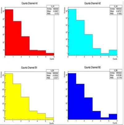
The frequency of the number of counts versus the number of counts appears in Figure 15 for channels 1, 2 3, 4, respectively. In the semilog plot these distributions are roughly linear, with negative slope. The average characteristics are statistically equivalent.
6 Conclusions
The four wire chamber detector works properly, in spite of the no ideal conditions were it was con-structed and operated. Amplitude signals of the order of 300 mV were acquired. No electronic amplifiers were required. It is a fast detector: rising time 5 ns; falling time 20 ns. It is good for Time of Flight studies. The digitalizing electronic board works fine. It is possible to count events produced by the detector from cosmic particles. Much more studies are needed, like efficiency, analogical signal amplitude dependence on detector high voltage, time resolution, space resolution, calibration, elec-tronic attenuation, detector alignment, data acquisition system, triggering. Big detectors are made assembling and synchronizing hundreds, even millions, of small detectors, to collect and combine information from each one.
7 Acknowledgements
Figure 14.Left, pulse from the mini four channel chamber compared with right pulse from Z. Ahmed et al, IOP Publishing Ltd and Sissa Medialab srl. Doi: 10.1088/1748-0221/9/01/P01009.
5 Results
The amplitudes of signals are of the order of 300 mV, but are variables; they are related with the energy cosmic particles deposit on the gas chamber. The average amplitude depends on the applied high voltage close to linearly, for both negative and positive voltages. The observed rise time is about 5 ns; the decay time, about 20 ns. See Figure 14. There is a comparison with signal from reference [19]. It is seen that this four wire chamber is faster than others, which makes it very convenient to study fast signals.
The frequency of the number of counts versus the number of counts appears in Figure 15 for channels 1, 2 3, 4, respectively. In the semilog plot these distributions are roughly linear, with negative slope. The average characteristics are statistically equivalent.
6 Conclusions
The four wire chamber detector works properly, in spite of the no ideal conditions were it was con-structed and operated. Amplitude signals of the order of 300 mV were acquired. No electronic amplifiers were required. It is a fast detector: rising time 5 ns; falling time 20 ns. It is good for Time of Flight studies. The digitalizing electronic board works fine. It is possible to count events produced by the detector from cosmic particles. Much more studies are needed, like efficiency, analogical signal amplitude dependence on detector high voltage, time resolution, space resolution, calibration, elec-tronic attenuation, detector alignment, data acquisition system, triggering. Big detectors are made assembling and synchronizing hundreds, even millions, of small detectors, to collect and combine information from each one.
7 Acknowledgements
CONACyT grant CONACYT, Fondo I0017 Fondo SEP - CONACYT Solicitud 000000000223179. The mole of students which participates in these projects. Luis J. Arceo, Miguel A. Hernández, Diego A. Andrade, María L. Rodríguez, Everardo Granados, Oscar E. Moreno, Karla N. Herrera, Raúl A. Gutiérrez, Francisco J. Rosas, Alfredo Martínez, Carlos A. Cervantes.
Figure 15.Frequency of counts Vs number of counts for each four mini wirechamber channel.
References
[1] H. Stelzer, Nucl. Inst. And Meth.133,499-413 (1976).
[2] D. V. Harrach and H. J. Specht, Nuclear Instruments and Methods 164 (1979) 477-490. [3] R. Santonico and R. Cardarelli, Nuclear Instruments and Methods 187 (1981) 377-380. [4] I. Crotty, et al, Nucl. Inst. and Methods in Physics Research A329 (1993) 133-139.
[5] R . Cardarelli, A. Di Ciaccio and R. Santonico, Nucl. Inst. and Meth. in Phy. Res. A 333 (1993) 399-403.
[14] P. Paolucci et al, Published By IOP Publishing For Sissa Medialab, Special Issue On Resistive Plate Chambers And Related Detectors Rpc2012 (2013).
[15] M. Morales et al, Published By IOP Publishing For Sissa Medialab, Special Issue On Resistive Plate Chambers And Related Detectors Rpc2012 (2013).
[16] P. Fonte, Published By IOP Publishing For Sissa Medialab, Special Issue On Resistive Plate Chambers And Related Detectors Rpc2012 (2013).
[17] R. Iuppa, Published By IOP Publishing For Sissa Medialab, Special Issue On Resistive Plate Chambers And Related Detectors Rpc2012 (2013).
[18] M. Widgoffet al, GEM TN-92-206 Rev. A. (1992).
[19] Z. Ahmed et al, IOP Publishing Ltd and Sissa Medialab srl. Doi: 10.1088/