Available online: https://journals.pen2print.org/index.php/ijr/ P a g e | 609
Design And Analysis Of Marine Engine Crankshaft Made Of Epoxy E Glass
Using Fea
Dr. K .RAMBABU1, AMARA.SANKAR2 Professor1, Mtech2
[email protected],[email protected] DEPARTMENT OF MECHNICAL ENGINEERING SIR C.R.REDDY COLLEGE OF ENGINEERING, ELURU
ABSTRACT
Crankshaft is one of the component in an I.c engine which is converts the reciprocating motion of the piston to motion is rotary. Where as in this reciprocating compressor .it converts to the rotary motion. In order to do the conversion between the two motions, the crank shaft has “crank throws” or “crankpins” additional bearing on surfaces whose axis is offset from that the crank, to which “big ends “of the connecting rods from each cylinder attach.
A crankshaft of 4 stroke single cylinder I.C Engine. so that the two revolution of crankshaft for each stroke. In this peak pressure acting on particular engine crankshaft. The crankshaft of the located by model is designed using of CAD SOFTWARE CATIA V5.the accurate dimensions of that material standards. CATIA V5 the best design software in design tools it can be easily design components based on that particular dimensions and analysis accurate results in ANYSIS.
In this project to compare optimization and analysis of the crankshaft on two different materials Aluminum Allo and Epoxy E Glass. This results to be taken and evaluated given load conditions and following the deformation results are shown in ANSYS.
1. INTRUDUCTION
Now a days automobile industries to be facing huge number of issues and then requires to be responses in order to be present competitive. Present competitive world has to produce components with reasonable cost and production values should became high. The global market companies is use the high software tools like the computers CAD tools and thesaurus in the f.e.a . if any component can be designed by the with help of Optimization techniques and then its numerical methods. It should be design a solid model by using CAD tools, the condition and operating mechanism how to meet the components in production time .because of using the modern methods it will reach the competitive with in little span.
The
general
considerations
of
designing a crankshaft;
The Crankshaft materials different kind of materials is to be usually cast iron, steel forging, cast steel, modular iron it produce is easily crankshaft. In order to strength would be follow design it approximately same in list then it low expensive follow. it will be made in shape it not following . then cranks certainly with high outcomes
Crank Materials and Construction
Available online: https://journals.pen2print.org/index.php/ijr/ P a g e | 610
critical conditions if you face any problem that the chose alternator.
Cranks Influence on Parts
Then changing low and mid rpms then the crank shaft size will increase to require torque. It will be design taken the modified crank shaft it output of torque range will be same of the engine speed. If the connected connecting rod it will be changes of stroke intake flow velocities are to be created. it also effected the piston value
By the way the use of internal resistance of the crank is to be decide to decrease then the engine acceleration very firstly then will get to the best result in compression ratio .then it applies dynamic pressure on the single cylinder then it recovers the power loss in rarer cylinder it to be use the rocker ratio then sever them itself .shade higher ratio is improve by high rpm power of it initial cost.
First of all we know how much amount of deflection of the crankshaft it will use be hide of working of rear cylinder in engine. Deflection of was occurred in reward cylinder it be decrease the position of cylinder it will related to rear cylinder then to be help of sparking of in engine it also help to the cam and crank to decrease it. the total deformation amount of crank shaft deflection is to effect the use of torsion vibration in damper it usually to decrease amount of life span .
2. CRANKSHAFT DESIGN ISSUES
In present situations engineer to design a product they should be flow the rule of design software tools. To compare the other products what is the design values how to overcome the various standard requirements. should be follow the given criteria to be use the perfect design should
take the some bending and tensional strength to be created how much amount of mass moment inertia is to be need.by the using the different crank shaft designs to be checked in the different accepts to solve the problems of crank fatigue Tensional resistance frequency high.beacause of high stiffness and the bending reflection to be reduced the regions .in case the friction increased different journals to be disturb the dynamic film and it will be peak points. it will be increase the leakage of greater radial it should be cause of losses lubrication
If you applied to the load of metal part it will be deflected of parts and there is no rigid.in case of small crankshaft a deflection will be large. By the way use of spring response to be like behaves the one degree to another degree. the ultimate results stress level is to be calculated by using material ultimate strength the stiffness the particular material to be calculated results of to its properties. Young’s modulus of material and modulus of elasticlikity
Basically you have to the two components then that are to be identical to each other in all cases but the exception in only conditions e tensile strength. If you can compare the two.
Available online: https://journals.pen2print.org/index.php/ijr/ P a g e | 611
3. Dimensions diagram crankshaft:
Available online: https://journals.pen2print.org/index.php/ijr/ P a g e | 612
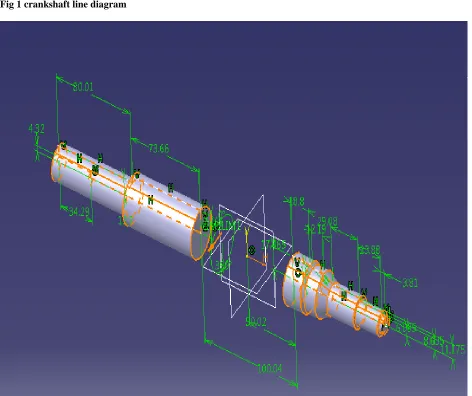
4. HOW TO DRAW CRANK SHAFT IN CATIA
Fig 1 crankshaft line diagram
Available online: https://journals.pen2print.org/index.php/ijr/ P a g e | 613
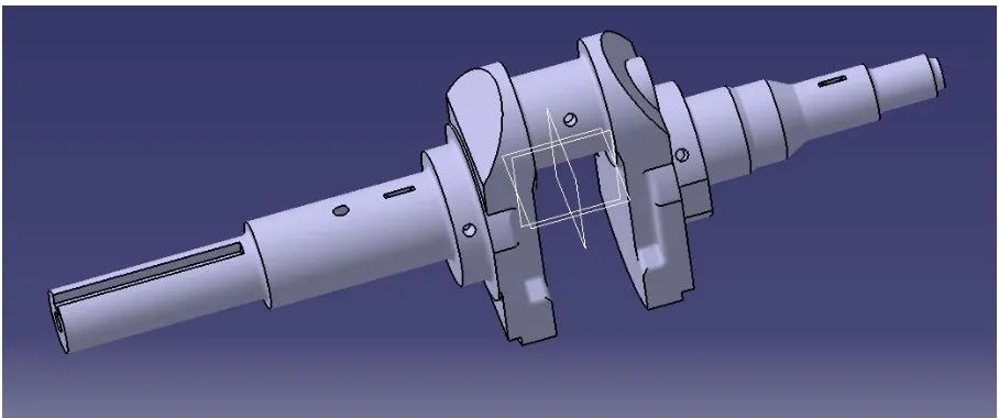
Fig 3 final crank shaft
5. Material properties to be using Aluminum alloy
Available online: https://journals.pen2print.org/index.php/ijr/ P a g e | 614
6. RESULTS
ALUMINUM ALLOY
Fig 4 crankshaft
MESH
Fig 5 mesh
STATIC STRUCTURAL
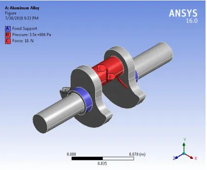
Fig 6 static structural TOTAL DEFORMATION
Fig 7 total deformation
EQUIVALENT ELASTIC STRAIN
Statistics
Nodes 12395
Available online: https://journals.pen2print.org/index.php/ijr/ P a g e | 615
Fig 8 equivalent elastic strain EQUIVALENT STRESS
Fig 9 Equivalent stress
EPOXY E GALSS
TOTAL DEFORMATION
Fig 10 Total deformation
EQUIVALENT ELASTIC STRAIN
Fig 11 Equivalent elastic strain EQUIVALENT STRESS
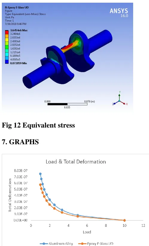
Fig 12 Equivalent stress 7. GRAPHS
Available online: https://journals.pen2print.org/index.php/ijr/ P a g e | 616
Graph 2. load and equivalent strain
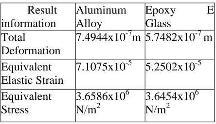
Graph 3. load and equivalent stress RESULT TABLE
Table 1. Result of Crankshaft
8. CONCLUSION
According to the solution in software the values of both materials when its comparison was done. The deformation is less in Epoxy E Glass when compared to that of the Aluminum Alloy, the maximum stress
is induced in Aluminum Alloy is more when compared Epoxy E Glass, the strain is more in Epoxy E Glass when compared to that of Aluminum Alloy. Hence the Epoxy E Glass is best.
REFERENCES
1. Hall, Bert S. (1979), The Technological Illustrations of the So-Called “Anonymous of the Hussite Wars”. Codex Latinus Monacensis 197, Part 1, Wiesbaden: Dr. Ludwig Reichert
Verlag, ISBN 3-920153-93-6 .
2. Al-Hassan, Ahmad Y.; Hill, Donald R. (1992), Islamic Technology. An Illustrated History, Cambridge University Press, ISBN 0-521-42239-6 .
3. Laur-Belart, Rudolf (1988), Fuehrer duchy Augusta Raurica (5th ed.), August
Result information
Aluminum Alloy
Epoxy E Glass
Total
Deformation
7.4944x10⁻⁷m 5.7482x10⁻⁷ m
Equivalent Elastic Strain
7.1075x10⁻⁵ 5.2502x10⁻⁵