Design of High Gain Lens Antenna by Using 100% Transmitting
Metamaterials
Qiu-Rong Zheng1, *, Bi-Cheng Lin2, and Bing-Han Zhou1
Abstract—A transmitting lens antenna using Huygens matematerials is proposed. The type of metamaterial has a 100% transmission. For obtaining a high gain antenna, a patch antenna is placed at the focal point of the metasurface as a feed source, and then quasi-spherical wave can be transformed to plane wave. As demonstration of the concept, a lens antenna, working at frequency of 10 GHz is designed, fabricated and measured. Numerical and experimental results agree well with each other. The measured results show that the gain has been enhanced about 11.2 dB.
1. INTRODUCTION
Until now, meta-materials have attracted many scientists and engineers for their strong capabilities in manipulating electromagnetic (EM) wave-front, especially for meta-surfaces (MSs). Many advantages in meta-surfaces have led to various fascinating phenomena and practical applications, such as anomalous refraction/reflection [1–9], conversion from propagation wave to surface wave [10, 11], vortex beam [12, 13], and holograms [14–18]. As a kind of MS, Huygens elements have been widely used in meta-devices design (i.e., metasurface realizing beam bending effect) due to their high transmission property [3]. Planar meta-lens, exhibiting unique converging property for the incident EM wave, has attracted a lot of attention, especially since the proposal of Pendry’s super lens [19]. For instance, an ultrathin and flat meta-surface working in reflection geometry has been engineered, which solves impedance mismatch problem and can realize focusing effect efficiently [20]. Moreover, bifunctional reflective lens has been designed to achieve Luneburg lens and Maxwell-fisheye simultaneously [21]. For obtaining the high-gain antenna, many methods have been mentioned in recently years, such as utilizing arrays [22], reflectors [23], cavities [24] and lens antenna [25]. However, all conventional antenna arrays suffer from complex feed network. Reflectors always have a large profile which leads to difficult fabrication. Cavities, just as Fabty-perot, have the weakness of narrow bandwidth. A conventional transmitting MS needs two or three layers to achieve high gain, which makes its fabrication difficult with expensive cost. Multibeam antennas using a single metasurface aperture with a single source and multisource have been investigated in [26]. In this paper, Huygens meta-materials are designed for high-gain lens antennas to conquer the problems of high profile and hard fabrication. The focusing effect has been verified as well as its reverse effect.
Thus, the transmission phase has a flat slope due to the non-resonant property of the elements. The EM response of the elements is analyzed by using finite-difference time-domain (FDTD) simulator (CST) in Section 2, and the working principle to achieve 100% transmission amplitude with arbitrary phase is proposed. In Section 3, transmissive lens is engineered by these meta-atoms. Obviously, these meta-atoms satisfy a parabolic-phase profile. A patch antenna is put at the focal point to make the reverse effect, which can achieve the high-gain antenna. In Section 4, far-field measurement is performed
Received 2 June 2018, Accepted 9 August 2018, Scheduled 22 August 2018 * Corresponding author: Qiu-Rong Zheng (zqr1620@sina.com).
1 Information and Navigation College, Air Force Engineering University, Xi’an, Shannxi 710077, P. R. China. 2 Air and Missile
to demonstrate its effect, which agrees well with the simulation. Finally, Section 5 concludes the whole paper.
2. ANALYSIS OF THE META-ATOMS
In this section, the working principle of a set of meta-atoms with total transmissions is presented. Huygens elements are chosen as the basic meta-atoms [3]. As shown in Fig. 1(a), the EM wave-front is parallel to surface of the proposed meta-atoms, unlike the others which the EM wave-font is perpendicular to, and besides, what the system of our meta-atoms contain in this article is not only the meta-atoms themselves but also the air space around the meta-atoms.
(a) (b)
(c) (d)
(e)
Figure 1. (a) Schematics of the meta-atom; (b) transmission amplitudes and phases of the meta-atoms; (c) top view; (d) bottom view of the meta-atom, and a = 0.2 mm, A = 2∗a= 0.4 mm, g = 0.3 mm,
The mechanisms of the meta-atoms can be explained as shown in [26]. The simulated results by FDTD are:
Ze = η 2
1 + (R+T)
1−(R+T) (1)
Zm = 2η1 + (R−T)
1−(R−T) (2)
whereZmandZeare penetrable surface electric impedance and penetrable surface magnetic impedance;
η is the wave impedance of the free space;R andT are the reflected and transmissive coefficients of the meta-atoms. When|T|= 1,R= 0, the theoretical results are:
Ze = iη 2cot ϕ t 2 (3)
Zm = −i2ηtan
ϕ
t 2
(4)
where ϕt is the transmission phase. The results can be seen in Fig. 1(e), and they coincide well with each other. The final size of elements is obtained with different phases by using FDTD simulations. For example, a representative meta-atom is selected to further analyze the working principle, with its schematics shown in Fig. 1(a). The meta-atom consists of two metallic layers, separated by a substrate with h = 1.5 mm, εr = 2.65 and tanδ = 0.003. Its working frequency is chosen at 10 GHz. Fig. 1(b) shows the transmission amplitudes and phases. It can be clearly seen that the transmission amplitudes have high values better than 0.98, while its phases are about 20.1◦, respectively. With the same method, other meta-atoms can be designed with high transmission amplitudes and phases covering 360◦variation range. Figs. 1(c) and (d) show the top and bottom views of the representative meta-atom.
3. TRANSMISSIVE LENS DESIGN
In this section, high-transmission coefficient meta-atoms are used to design the lens. The meta-surface should satisfy the following parabolic refraction-phase profile for the incident electric and magnetic (EM) waves withz direction propagation andy-polarized E field.
ϕ(x, y) =k0
x2+y2+f2 0 −f0
+ϕ0 (5)
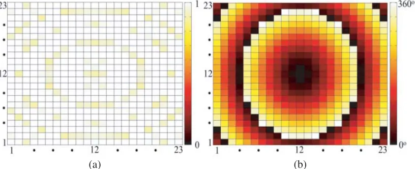
wherek0= 2π/λ0 is the propagation constant in free space,f0 the focal distance,ϕ0the reference phase, and λ0 the wavelength at the 10 GHz. f0 = λ0 = 30 mm is selected. To demonstrate the focal effect, 23×23 meta-atoms satisfy the phase-profile in thexoy-plane according to Eq. (1) for HMS design used.
(a) (b)
Fig. 2(a) and Fig. 2(b) show the transmission amplitude of each meta-atom and the transmitting phase distribution of the proposed meta-surface, respectively. It can be seen that all transmission amplitudes are over 0.9, even to 1.
For exhibiting the focal characteristic, the simulation of the HMS has been completed. Fig. 3(a) and Fig. 3(b) depict the simulated electric field with polarization parallel toy axis along the yoz-plane and xoz-plane, respectively. The EM wave in front of the MS is very weak, which means less reflection, and the focal effect is significantly excellent. The power distributions along the intersection lines ofyoz -planexoz-plane are shown in Fig. 4(a) and Fig. 4(b), respectively. For making sure the location of focal point, the power distribution of center line (y = 0), shown in Fig. 4(c) is retrieved. The results show that the focal length f = 26 mm at 10 GHz. The focal point with a slight deviation can be explained by the finite-size effect.
(a) (b)
Figure 3. Simulated electric field (Ey) distribution of the HMS at 10 GHz in (a) yoz-plane and (b)
xoz-plane.
(c)
Figure 4. The power flow in (a)yoz-plane and (b)xoz-plane; (c) normalized power intensity on thez axis under plane wave at 10 GHz.
(a) (b)
(d) (c)
(e)
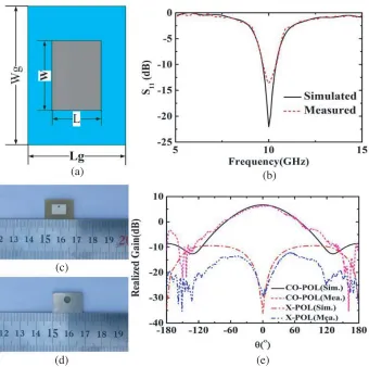
Figure 5. (a) the patch antenna located in the focal source,L= 6.4 mm,Lg = 12.8 mm,W = 9.1 mm,
4. LENS ANTENNA DESIGN AND TEST
For obtaining the best performance of the lens antenna, the source antenna should be put at the focal point. Fig. 5(a) depicts the schematic of the source antenna, and Fig. 5(b) shows that the minimum reflection coefficient of the source antenna is at 10 GHz. Besides, the gain of the patch antenna is 6.5 dB. Thus, the meta-surface can be put in the front of the patch antenna. Figs. 6(a)–(d) depict the electric field (Ey) distribution in different intersections, and the wave-front becomes significantly flat when the patch antenna is with proposed meta-surface in bothyoz-plane andxoz-plane.
(a) (b)
(c) (d)
Figure 6. Simulated electric field (Ey) distribution of the transmissive lens antenna at 10 GHz in (a), (b) yoz-plane and (c), (d) xoz-plane, respectively. For the patch antenna (a), (c) without and (b), (d) with HMS.
(a) (b)
(c)
(a) (b)
(c) (d)
Figure 8. (a) 3-D simulated far-field radiation pattern of the Transmissive lens antenna at 10 GHz; simulated and measured gain of the proposed lens antenna at (b) 10 GHz, (c) 9.7 GHz and (d) 10.4 GHz.
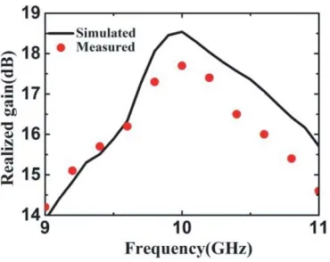
Finally, we can get the 1-d gain bandwidth from Fig. 9. It depicts the realized gain against frequency. Thus the 1-d gain bandwidth in simulation is from 9.7 GHz to 10.4 GHz, while in measurement it is from 9.7 GHz to 10.3 GHz, from which the consistence can be seen between the simulated and the measured results.
5. CONCLUSION
In summary, a novel microwave lens antenna with a high gain of 17.7 dB by using Huygens meta-atoms is proposed. Each Huygens meta-atom introduces an electric structure and a magnetic structure, which can provide nearly 100% transmission by carefully designing the size of the structures. For practical demonstration, a meta-lens antenna working at 10 GHz is designed. The lens antenna advances in many aspects such as high gain, broad bandwidth as well as easy fabrication. The design provides a new method to design high-gain meta-device with other functionalities.
ACKNOWLEDGMENT
Project supported by the National Natural Science Foundation of China (Grant No. 61571461).
REFERENCES
1. Yu, N. F., P. Genevet, M. A. Kats, F. Aieta, J. P. Tetienne, F. Capasso, and Z. Gaburro, “Light propagation with phase discontinuities: Generalized laws of reflection and refraction,” Science, Vol. 334, 333–338, 2011.
2. Ni, X., N. K. Emani, A. V. Kildishev, A. Boltasseva, and V. M. Shalaev, “Broadband light bending with plasmonic nanoantennas,” Science, Vol. 335, 427, 2013.
3. Pfeiffer, C. and A. Grbic, “Metamaterial Huygens’ surface: Tailoring wave fronts with reflectionless sheet,” Phys. Rev. Lett., Vol. 110, 197401, 2013.
4. Xu, H. X., G. M. Wang, T. Cai, J. Xiao, and Y. Q. Zhuang, “Tunable Pancharatnam-Berry metasurface for dynamical and high-efficiency anomalous reflection,”Opt. Express, Vol. 24, 27836– 27848, 2016.
5. Wong, J. P. S., M. Selvanayagam, and G. V. Eleftheriades, “Polarization considerations for scalar Huygens metasurfaces and characterization for 2-D refraction,” IEEE Trans. Microw. Theory Techn., Vol. 63, 913–924, 2015.
6. Pfeiffer, C., N. K. Emani, A. M. Shaltout, A. Boltasseva, V. M. Shalaev, and A. Grbic, “Efficient light bending with isotropic metamaterial Huygens’ surfaces,”Nano Lett., Vol. 14, 2491–2497, 2014. 7. Pors, A., O. Albrektsen, I. P. Radko, and S. I. Bozhevolnyi, “Gap plasmon-based metasurfaces for
total control of reflected light,” Sci. Rep., Vol. 3, 2155, 2013.
8. Ma, H. F., G. Z. Wang, G. S. Kong, and T. J. Cui, “Independent controls of differently-polarized reflected waves by anisotropic metasurfaces,”Sci. Rep., Vol. 5, 9605, 2015.
9. Farahani, M. F. and H. Mosallaei, “Birefringent reflectarray metasurface for beam engineering in infrared,”Opt. Lett., Vol. 38, 462–464, 2013.
10. Sun, S. L., Q. He, S. Y. Xiao, Q. Xu, X. Li, and L. Zhou, “Gradient-index meta-surfaces as a bridge linking propagating waves and surface waves,” Nat. Mater., Vol. 11, 426–431, 2012.
11. Sun, W., Q. He, S. Sun, and L. Zhou, “High-efficiency surface plasmon meta-couplers: Concept and microwave-regime realizations,”Light Sci. Appl., Vol. 5, e16003, 2016.
12. Yu, S., L. Li, G. Shi, C. Zhu, X. Zhou, and Y. Shi, “Design, fabrication, and measurement of reflective metasurface for orbital angular momentum vortex wave in radio frequency domain,”
Appl. Phys. Lett., Vol. 108, 121903, 2016.
13. Yu, S., L. Li, G. Shi, C. Zhu, and Y. Shi, “Generating multiple orbital angular momentum vortex beams using a metasurface in radio frequency domain,” Appl. Phys. Lett., Vol. 108, 241901, 2016. 14. Huang, Y. W., W. T. Chen, W. Y. Tsai, P. C. Wu, C. M. Wang, G. Sun, and D. P. Tsai, “Aluminum
plasmonic multicolor meta-hologram,” Nano Lett., Vol. 15, 3122–3127, 2015.
16. Chen, W. T., K. Y. Yang, C. M. Wang, Y. W. Huang, G. Sun, I. Chiang, C. Y. Liao, W. L. Hsu, H. T. Lin, S. Sun, L. Zhou, A. Q. Liu, and D. P. Tsai, “High-efficiency broadband meta-hologram with polarization-controlled dual images,” Nano Lett., Vol. 14, 225–230, 2014.
17. Wen, D., F. Yue, G. Li, G. Zheng, K. Chan, S. Chen, M. Chen, K. F. Li, P. W. H. Wong, K. W. Cheah, E. Y. B. Pun, S. Zhang, and X. Chen, “Helicity multiplexed broadband metasurface holograms,” Nat. Commun., Vol. 6, 8241, 2015.
18. Zheng, G., H. M¨uhlenbernd, M. Kenney, G. Li, T. Zentgraf, and S. Zhang, “Metasurface holograms reaching 80% efficiency,” Nat. Nanothchnol., Vol. 10, 296–298, 2015.
19. Pendry, J. B., “Negative refraction makes a perfect lens,”Phys. Rev. Lett., Vol. 85, 3966, 2000. 20. Li, X., S. Xiao, B. Cai, Q. He, T. J. Cui, and L. Zhou, “Flat metasurfaces to focus electromagnetic
waves in reflection geometry,” Opt. Lett., Vol. 37, 4940–4942, 2012.
21. Wan, X., X. Shen, Y. Luo, and T. J. Cui, “Planar bifunctional Luneburg-fisheye lens made of an anisotropic metasurface,” Laser Photonics Rev., Vol. 8, 757–765, 2014.
22. Milligan, T. A.,Modern Antenna Design, 2nd Edition, Willey, NJ, Hobeken, 2005.
23. Cutler, C. C., “Parabolic-antenna design for microwaves,” Proc. IRE, Vol. 35, 1284–1294, 1947. 24. Vigueras, M. G., J. L. Gomez-Tornero, G. Goussetis, A. R. Weily, and Y. J. Guo, “Efficient
synthesis of 1-D Fabry-Perot antennas with low side-lobe levels,”IEEE Antennas Wireless Propag. Lett., Vol. 11, 869–872, 2012.
25. Li, H. P., G. M. Wang, H. X. Xu, T. Cai, and J. G. Liang, “X-band phase-gradient metasurface for high-gain lens antenna application,”IEEE Transactions on Antennas and Propagation, Vol. 63, 5144–5149, 2015.