Scholarship@Western
Scholarship@Western
Electronic Thesis and Dissertation Repository
10-15-2019 11:15 AM
Progress Toward Durable Icephobic Materials
Progress Toward Durable Icephobic Materials
Matthew J. Coady Supervisor
Ragogna, Paul J.
The University of Western Ontario Graduate Program in Chemistry
A thesis submitted in partial fulfillment of the requirements for the degree in Doctor of Philosophy
© Matthew J. Coady 2019
Follow this and additional works at: https://ir.lib.uwo.ca/etd
ii
Abstract
Ice accumulation is a major engineering challenge in many fields including aerospace, power generation, transportation, and infrastructure. A variety of solutions are being researched to address this challenge. Perhaps the most promising method of combating ice accumulation is by applying coatings with low values of interfacial ice adhesion strength, τice. Icephobic materials are
those with ice adhesion below 100 kPa, and it has been shown that passive delamination can occur on surfaces with τice below 20 kPa. While various low adhesion surfaces have been prepared,
durability concerns pervade applications where surfaces experience repeated icing or freeze-thaw cycles, mechanical abrasion, and particulate erosion. The present thesis explores methods of improving the durability of state-of-the-art icephobic materials in order to make them more suitable solutions to ‘the icing problem.’ Ice adhesion was measured using in-house load cell and
iii
iv
Ice accumulation occurs in many places in nature and in industry, threatening to destroy vital infrastructure such as roads and power transmission lines. The North American Ice Storm of 1998 is an example of the expense of extreme weather, causing $5 Billion in damage in Canada over the course of six days and cost 35 Canadians their lives. Preventing large-scale damage to our infrastructure is of critical importance to protect lives, and to reduce the cost of maintenance paid by taxes.
Icephobic (ice-fearing) coatings are those that resist or prevent ice growth on their surfaces. To date, the best-performing materials are rubber-based and oil-containing coatings operating on a simple principle: rigid materials like ice do not adhere to flexible materials like rubber and oil. While there has been considerable success in applying well-known rubbers like silicones, challenges remain before these materials can be used on a large scale. Firstly, the materials must be made more durable. Icephobic materials, in particular those including oils, are prone to damage through abrasion, such as that experienced if sand or ice particles are blown across surfaces by high winds. Secondly, coatings must be applied to surfaces on a huge scale, such as on all powerlines within a city. To address these challenges, we hope to toughen these materials through different chemical modifications. These methods are presented in the present thesis: 1) Using cross-linking in silicone rubber coatings to retain oil in icephobic materials; 2) Inscribing special surface morphologies in rubber surfaces to reduce ice growth; 3) Making silicones more durable by incorporating plastic-like materials; 4) Decreasing ice adhesion strength on commercial adhesive tapes by changing how they adhere to their substrates.
v
Co-Authorship Statement
Chapter 2 has been adapted from the journal article “Icephobic Behavior of UV-Cured Polymer Networks: Improving SLIPS Durability”, published in ACS Applied Materials and
Interfaces. Fabrication, testing, characterization (except AFM), and drafting of the article were done by Matthew J. Coady. Michael Wood, Kent E. Nielsen, Anne-Marie Kietzig, François Lagugné-Labarthet, and Paul J. Ragogna contributed to editing and content during the revision process. All AFM analysis was done by Gregory Q. Wallace.
Chapter 3 is a work of writing by Matthew J. Coady, based upon the journal article “Femtosecond laser micromachining of co-polymeric urethane materials”, written by Michael
J. Wood with contributions from the co-authors. Figures indicated were used with permission of the authors. Experimental work for the original article pertaining to the preparation of materials was done by Matthew Coady, as was additional characterization by IR spectroscopy and thermal gravimetric analysis and differential scanning calorimetry.
Chapter 4 has been adapted from the journal article “Highly cross-linked UV-cured siloxane copolymer networks as icephobic coatings”, submitted to Langmuir. Preparation of the coatings, characterization other than nanoindentation and AFM, ice adhesion testing, and drafting of the article were done by Matthew Coady. Nuwansiri Getangama performed AFM analysis, and Aria Khalili performed nanoindentation for hardness measurements. Paul Ragogna and John de Bruyn reviewed and edited the manuscript prior to submission.
vi
Acknowledgments
I would like to thank those who helped me throughout my graduate career. Firstly, Prof. Paul Ragogna for providing me the opportunity to pursue my doctorate in his group, and for his guidance over the years. Thank you as well to the researchers at 3M Canada who took time to review much of my work, and for providing insight toward new research directions. Thank you to all the co-authors with whom I have had the pleasure of working.
Ragogna Group members present, and past have been instrumental to the completion of this document; thank you for your support. A special thanks to my undergraduate lab partner, Vanessa Béland, who later became my mentor when joining the Ragogna group: a true scientist (but I have to say, I’m still better at math). Thanks as well to Brad Berven, who showed me the ropes of anti-icing research, and to Tim Stephens who I had the opportunity to mentor in the lab. You guys are the only ones who really appreciate what it’s like to work in the Cold Weather Biome!
Thank you to all the support staff and faculty at Western, especially the crew in the Chemistry Electronics Shop and the Biotron, without whom measurements would have been impossible. Thanks to my supervisory committee for taking the time to review my thesis, and for your valuable input to my research.
Thank you to my friends and family. My friends have been a continuous influence (positive or otherwise) on me, my research, and my extra-curricular activities. My family have provided continuous support. Mom and Dad, you have always been there for me, and I appreciate everything that you’ve done to help me reach my goals. Alyssa and Bruno, thanks
for being there for me when I needed it, even if you were unaware.
Lastly, thank you to my wife Lauren. Your dedication and focus are awe-inspiring, and you make me strive to be a better person. I’m sorry about the papers all over the apartment.
vii
Table of Contents
Abstract ... ii
Summary for Lay Audience ... iv
Co-Authorship Statement... v
Acknowledgments... vi
Table of Contents ... vii
List of Tables ... x
List of Figures ... xi
List of Abbreviations ... xvi
Preface... xviii
Chapter 1 ... 1
1 Introduction ... 1
1.1 The Impetus of Icing Prevention... 1
1.2 Adhesion: A Primer ... 2
1.3 Other Factors Influencing Ice Adhesion: The Interface ... 7
1.4 Strategies to Reduce Ice Accumulation ... 11
1.5 Passive Methods of Ice Abatement ... 12
1.6 Icephobic Materials ... 20
1.7 Remaining Challenges and Scope of Thesis ... 26
1.8 References Cited ... 27
Chapter 2 ... 36
2 Icephobic behavior of UV-cured polymer networks incorporated into slippery lubricant-infused porous surfaces: Improving SLIPS durability ... 36
2.1 Introduction ... 36
2.2 Experimental ... 38
viii
2.4 Conclusions ... 47
2.5 References Cited ... 47
Chapter 3 ... 49
3 Fundamentals of Lasing Elastomeric Urethane Coatings to Prepare Icephobic Microstructures ... 49
3.1 Introduction ... 49
3.2 Experimental ... 50
3.3 Results and Discussion ... 52
3.4 Conclusions ... 60
3.5 References Cited ... 60
Chapter 4 ... 65
4 Highly cross-linked UV-cured siloxane copolymer networks as icephobic coatings .. 65
4.1 Introduction ... 65
4.2 Experimental ... 67
4.3 Results and Discussion ... 69
4.4 Conclusions ... 76
4.5 References Cited ... 76
Chapter 5 ... 79
5 Creating Arrays of film/substrate detachments as a means of lowering ice adhesion strength ... 79
5.1 Introduction ... 79
5.2 Experimental ... 81
5.3 Results and Discussion ... 83
5.4 Conclusions ... 90
5.5 References Cited ... 91
Chapter 6 ... 93
ix
6.1 Summary and Conclusions ... 93
6.2 Future Work ... 96
6.2.1 Method Development... 96
6.2.1.1 Simulating Winter Weather in the Cold Weather Biome ... 96
6.2.1.2 Ice Adhesion and Interfacial Toughness ... 98
6.2.2 Material Development ... 100
6.2.2.1 Thermoplastic Elastomers / Vulcanizates ... 100
6.2.2.2 Graphene/Polymer Nanocomposites ... 101
6.3 References Cited ... 105
Appendices ... 107
Appendix A: Supporting Information for Chapter 2... 107
Appendix B: Supporting Information for Chapter 3 ... 112
Appendix C: Supporting Information for Chapter 4 ... 113
Appendix D: Supporting Information for Chapter 5... 122
x
List of Tables
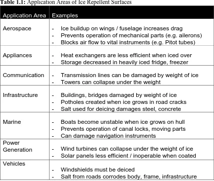
Table 1.1: Application Areas of Ice Repellent Surfaces ... 2
Table 2.1: Ice adhesion and wetting data for SLIPS and selected surfaces ... 43
Table 3.1: Gel content and swelling of polymer networks. Adapted with permission. ... 58
xi
List of Figures
Figure 1.1: Water contact angles (ϴc) on (left) a smooth hydrophobic surface, and (right) a smooth hydrophilic surface. ... 4
Figure 1.2:Diagram depicting the cause of surface energy (left) before cleavage, and (right) after cleavage. Circles represent lattice points in a crystalline material; grey for bulk, beige for surface. '!' indicate unbalanced forces on lattice points ... 5
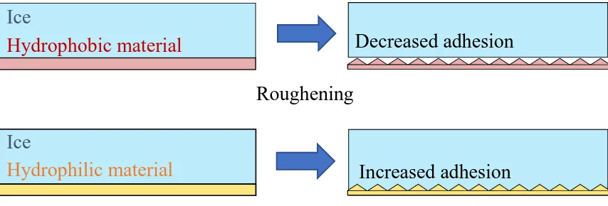
Figure 1.3: Illustration of changing adhesion with surface roughness for hydrophobic and hydrophilic materials. Roughness causes decreased water / ice adhesion on hydrophobic materials, and increased water / ice adhesion on hydrophilic materials. ... 6
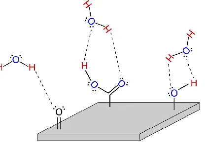
Figure 1.4: Hydrogen bonding to a generic surface with polar groups present. Hydrogen bonds are shown as dashed lines. ... 7
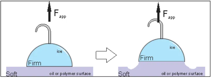
Figure 1.5: Depiction of interfacial cavitation. A force Fapp applied to two connected bodies, one soft and one firm, will bring about deformations in the soft body. ... 8
Figure 1.6:Illustration explaining the observation of interfacial slippage observed in an elastomer film adhered to a surface. (left) A polymer film on top of a rigid substrate, with no forces acting upon it. The polymer particles shown have no net force acting upon them, and therefore no slip is observed. (right) The polymer film is experiencing an extensive force as it is being peeled from the surface. A net force in the direction labelled ‘extension’ leads to a concomitant contraction and slippage of the polymer particles. ... 10
Figure 1.7: Illustration of (left) advancing and (right) receding contact angles. ... 13
Figure 1.8:Illustration of the Cassie-Baxter (left) and Wenzel (right) wetting states. Both have very high apparent contact angles. ... 14
Figure 1.9: Illustration of homogeneous nucleation. Liquid particles collide randomly, until a nucleus of critical size forms, leading to the formation of a crystal. ... 16
xii
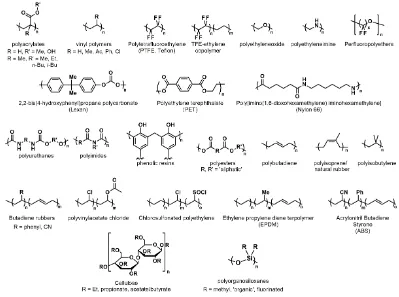
Figure 1.11: Chemical structures of polymers used in anti-icing / deicing research. ... 22
Figure 1.12: Fabrication of a generic slippery lubricant-infused porous surface, showing the formation of a trapped fluid layer deeper than the microstructure. ... 24
Figure 1.13: Extension and concomitant contraction of viscoelastic polymer chains in
response to stress on the ice/polymer interface (Fapp). This contraction causes cleavage where the media meet due to interfacial slippage. ... 26
Figure 2.1: Process diagram for the fabrication of UV-cured SLIPS ... 37
Figure 2.2: (left) SEM image of porous structure of anodized coupons. (right) FIB-etched cross-section of coupon edge used to measure approximate depth of porous oxide layer. Both images captured at 3.00 kV. ... 41
Figure 2.3: Comparison of wetting contact angle PAAO (left), silylated PAAO (mid) and oil-infused PAAO SLIPS (right). ... 41
Figure 2.4: AFM height images of 5 μm by 5 μm area of a) oil-only, b) Ebecryl 1360 and c)
Ebecryl 1360 plus oil ... 42
Figure 2.5: Deicing results for oil-only (red), oil+1360 (yellow) and oil+350 (blue) SLIPS samples. Solid lines indicate the mean values measured after n deicing cycles, while the shaded areas correspond to the standard error associated with those measurements. ... 43
Figure 2.6: EDX spectra of oil-only SLIPS. Top image taken of area where ice was not grown. Bottom image taken in a deiced area. ... 45
Figure 2.7: Oil+350 resin EDX and SEM results. (Top left) Spectrum before icing, with no aluminum seen at the surface. (Bottom) Spectra representing different areas observed by SEM after deicing, correlated to the SEM image (top right): a) where much of the silicon still resides in the surface, and b) where the coating has been completely removed. ... 46
Figure 3.1: (left) Ice interlocking with structure surface. (right) Release of ice occurring when a pillared surface is flexible. ... 49
xiii
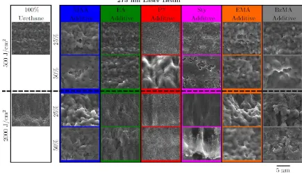
Figure 3.3: Scanning electron micrographs of the microstructures induced on the surface of the studied co-polymer materials irradiated with a 275 nm laser beam. Taken from Wood et al with permission. ... 54
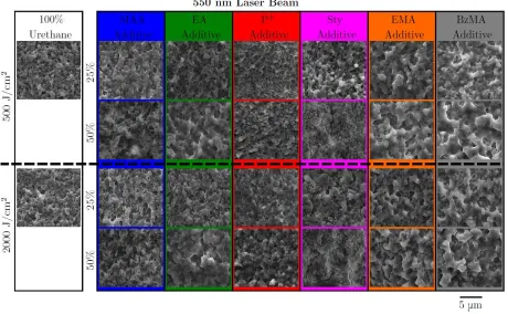
Figure 3.4: Scanning electron micrographs of the microstructures induced on the surface of the studied co-polymer materials irradiated with a 550 nm laser beam. Taken from Wood et al with permission. ... 55
Figure 3.5: Experimentally determined ionization threshold fluences of UV-cured polymer materials, irradiated with (a) 275 nm, and (b) 550 nm fs-laser beam, presented as a function of the number of laser pulses. Error bars represent the 95% confidence interval. Note that in many cases the error bar is smaller than the data marker. Adapted from Wood et al with permission. ... 56
Figure 3.6: Absorbance of (a) 275 nm wavelength light by the pristine polymer substrates, (b) 550 nm wavelength light by the pristine polymer substrates, (c) 275 nm wavelength light by the polymer substrates after ablation, and (d) 550 nm wavelength light after ablation. Used with permission. ... 57
Figure 3.7: Experimentally determined incubation coefficients ξ of UV-cured polymer materials irradiated with (a) 275 nm, and (b) 550 nm fs-laser beam. Error bars represent the 95% confidence interval. Adapted with permission. ... 59
Figure 4.1: Illustration of the differing cross-link densities in cured polymer networks with no comonomer (A) and with comonomer included (B). ... 67
Figure 4.2: Initial ice adhesion data of the three series of prepared coatings compared to EB1360. Red, blue, and green columns denote 5, 10 and 25 wt% comonomer. Error bars are the standard error of the measurements (n = 5). ... 70
Figure 4.3: SEM images showing wrinkling on surfaces of EB1360:Styrene coatings: a) EB1360, b) 5 wt% Sty, c) 10% Sty, d) 25 wt% Sty. ... 72
xiv
Figure 4.5: AFM height images showing wrinkles present in EB1360:Sty copolymer films. 73
Figure 4.6: Plots showing ice adhesion over time measure on prepared copolymer networks. Red, blue, and green data series represent 5, 10 and 25 wt% comonomer. ... 74
Figure 4.7: Plots showing durability of coatings to successive deicing tests. Samples visibly damaged from testing were removed from the complement as damage occurred. The average τice values in blue were calculated from intact samples only, and the orange plot shows the
number of samples with no visible damage. ... 75
Figure 5.1: Ice grown on a film (left) completely (normally) attached to the substrate, or (right) partially detached from the substrate. ... 80
Figure 5.2: Ice adhesion τice measured on commercial adhesive films. The right column of each series denotes films detached from the substrate under the iced area. (Aice = 0.28 cm2, Adet = 1 cm2). ... 81
Figure 5.3: Ice adhesion (τice) on commercial films with varied area of detachment between
the film and substrate (Aice = 1 cm2). ... 83
Figure 5.4: a) Image of ECO 360 applied to underside of 1577CW film, b) Pattern of ice column positions generated by Inkscape, c) and d) Ice columns corresponding to the first six and four remaining positions on the generated pattern. ... 84
Figure 5.5: Plots of ice adhesion measured on arrays of varying detachment size for: a) Masking tape, b) PVC tape, c) Aluminum shielding tape, and d) Skived PTFE film. ... 85
Figure 5.6: Plots showing the change in relative sample masses for films with varying
detachment size: a) masking tape, b) PVC tape, c) jacketing tape, and d) PTFE skived film. 86
Figure 5.7: Photos showing surface damage to a) normally attached PVC film, and films with b) 10 mm, c) 16 mm, and d) 20 mm detachments in the path of the abrasive wheels. ... 88
xv
PVC film, and films with b) 10 mm, c) 16 mm, and d) 20 mm detachments in the path of the Al2O3 particles. ... 89
Figure 6.1: Proposed construction of a rack containing an array of coated aluminum coupons at different angles relative to spraying apparatus (left, top view; right, side view). ... 97
Figure 6.2: Plot of force per unit width (x = 1cm) versus length (L) of iced areas. Force per unit width is constant after a critical length, Lcrit. ... 99
Figure 6.3: Experimental setup for measuring interfacial toughness using ice columns with a fixed width (x) and variable length (L). ... 99
Figure 6.4: Blending of acidic graphene suspension with polymers containing sodium
bicarbonate for concurrent dispersion and quenching. ... 103
xvi
List of Abbreviations
AFM atomic force microscopy
ASTM American Society for Testing and Materials
°C degrees Celsius
CAD Canadian dollars
CAH contact angle hysteresis
cm centimeters
CNT classical nucleation theory
CWB cold weather biome
DC direct current
DIA droplet impact apparatus
EDX energy dispersive x-ray spectroscopy
Fapp applied force
Fc centripetal force
fθ shape factor
g gram
G shear modulus
GPa gigapascals
h hours
J joule
kPa kilopascal
L length
Lc critical length
LMA lauryl methacrylate
m meter
mJ millijoule
MAA methacrylic acid
MMA methyl methacrylate
mol mole
n* critical nucleus size
PAAO porous anodic aluminum oxide
PDMS polydimethylsiloxane
PTFE polytetrafluoroethylene
PVC polyvinyl chloride
SEM scanning electron microscopy
SHS superhydrophobic surface
SLIPS slippery lubricant-infused porous surface
Sty styrene
xvii
TGA thermal gravimetric analysis
TPa terrapascals
TPE thermoplastic elastomer
USD U.S. dollars
UV ultraviolet
Wa work of adhesion
γ surface free energy
Γ interfacial toughness
ΔG*
n free energy of nucleation
ε strain
θC static contact angle
θA advancing contact angle
θR receding contact angle
νe cross-link density
xviii
Preface
Developing ice repellent materials is an interesting challenge. My favourite part about this research (more accurately, performing this research in Canada) is that whoever I speak to feels connected: they have had to deal with ice in some way, at some point, and likely will again soon. What is not obvious is how complex a problem ice adhesion is, and how diverse the research in the field. It’s an unusual problem and makes for a thesis that seems an awkward fit
for chemistry. For this reason, I have included this short preface, and a list of references that I believe are must reads for those interested in the field. Enjoy!
-Matt
John Sayward’s Special Report entitled “Seeking Low Ice Adhesion” should be the first
writing you consult. It frames the problem of adhesion and discusses the nascence of the field in such an accessible and interesting way, you must read it. I only wish that I had found this work earlier during my graduate studies.
Lars-Olof Andersson’s Licentiate Thesis entitled “Ice Accretion and Ice Adhesion to Polymer Materials” furthers some discussion presented by Sayward, and beautifully summarizes work
in the field up to 1993.
“Design of anti-icing surfaces: smooth, textured or slippery?” is a review by Michael Kreder,
Jack Alvarenga, Philseok Kim, and Joanna Aizenberg published in 2016. I think it effectively captures the climate of contemporary anti-icing research.
Kevin Golovin’s works published while at the University of Michigan with Anish Tuteja are
Chapter 1
1
Introduction
1.1
The Impetus of Icing Prevention
Ice is a diverse material that can be observed in many forms in nature, ranging from clouds to glaciers. These forms can be beautiful to view from a distance, but where humans interact with ice, it is a nuisance and a safety hazard. Icy sidewalks cause slips and falls, black ice causes motorists to lose control of their vehicles, downed power lines interrupt electricity and heating, and pose an electrocution risk. The underlying cause of these hazards is a simple matter of ice adhering to and accumulating on surfaces. While the problem is simple in nature, there is no consistently effective method of preventing ice accumulation. Prevention and removal encompass complex engineering challenges that have been researched for over a century.1 Interest in icing prevention was sparked in a variety of industries, often linked in some way to the military, for preventing ice build-up on marine vehicles, locks and dams, telecommunication lines and aircraft,2 with one of the earliest mentions of ice prevention in the literature was the 1940s by early commercial airlines “[…] anxious to make flying a safe routine in every type of weather.”1,3 These
concerns are responsible for the birth of ice prevention, and continue to inspire contemporary research in the field (Table 1.1).
form of corrosion damage to bridges and vehicles.7 In addition to annual costs associated with infrastructure maintenance, the acute costs of extreme weather (e.g. ice storms) also come at a great cost to the economy. In 2013 the Toronto ice storm cost the city over $100 Million CAD in repairs,8 which is a small evaluation compared to The Great Ice Storm of 1998, which cost thirty-five Canadians their lives, and an estimated “[…] $5.4 Billion [USD] in insurance claims, utility repairs and lost productivity […]”.9 This undoubtably
highlights the economic and health concerns for citizens in cold climates created by ice accumulation. Methods of preventing ice accumulation must be developed in order to protect the lives and tax dollars of Canadian citizens, and others globally. In pursuit of this goal, one must first develop an understanding of why ice adhesion occurs and what factors influence it, as well as the materials and methods that encompass the state of the art in ice prevention.
Table 1.1: Application Areas of Ice Repellent Surfaces
Application Area Examples
Aerospace - Ice buildup on wings / fuselage increases drag
- Prevents operation of mechanical parts (e.g. ailerons) - Blocks air flow to vital instruments (e.g. Pitot tubes)
Appliances - Heat exchangers are less efficient when iced over
- Storage decreased in heavily iced fridge, freezer
Communication - Transmission lines can be damaged by weight of ice
- Towers can collapse under the weight
Infrastructure - Buildings, bridges damaged by weight of ice
- Potholes created when ice grows in road cracks - Salt used for deicing damages steel, concrete
Marine - Boats become unstable when ice grows on hull
- Prevents operation of canal locks, moving parts - Can damage navigation instruments
Power
Generation - Wind turbines can collapse under the weight of ice
- Solar panels less efficient / inoperable when coated Vehicles
- Windshields must be deiced
1.2
Adhesion: A Primer
Adhesion describes the attachment of a material to another, forming what is often called a joint or adhesive bond (not to be confused with chemical bonding). The forces holding a joint together vary from system to system, but typically they include interactions described by one or more of the following adhesion theories:10 (1) mechanical interlocking theory, where adhesives infiltrate surface asperities of a material; (2) electrostatic theory, involving electron transfer between adhesive and substrate due to dissimilar band structure; (3) diffusion theory, where molecules of the adhesive/substrate interdiffuse, (4) wetting theory, which proposes that adhesion occurs because of molecular contact between two materials and the surface forces that develop as a result of Van der Waals forces; (5) chemical bonding theory, which attributes adhesion to surface chemical forces, such as covalent or ionic bonding, or hydrogen bonding; and (6) weak boundary layer theory, which deals primarily with bond failure, identifies the cause of failure in some cases to be weak attachment of a surface layer to the bulk, such as some metal oxides to their metals. Ice adhesion is generally considered to result from a combination of mechanical interlocking, wetting, and chemical bonding. Interlocking occurs when water infiltrates, freezes and expands into surface asperities, wetting is the spreading and adhesion of liquid water to a surface, and hydrogen bonding describes the sharing of water hydrogen atoms with polar surface groups. The formation of an adhesive bond has other requirements, as well. One material must ‘wet’ the other material, which allows for close interaction of the
chemical groups or surface asperities that cause bonding. Next, a material must ‘set’; that is undergo a change that allows it to remain adhered to the other material. Ice sets when it undergoes a transition from liquid to solid as it cools to ~0 °C when it adheres to a solid.
The set material must then undergo significant enough deformations as to allow for the release of any elastic stresses that could cause the joint to fail 11 The most often discussed adhesion requirement related to ice adhesion is the surface wetting of the material.
droplet, but the leaf is not, or is to a lesser extent. A material that shows good droplet spreading is often called hydrophilic and non-wetting surfaces are called hydrophobic. The degree to which a material is wetted is measured using contact angle (Figure 1.1).
A line tangent to the surface of the droplet creates angle ϴc when drawn to the droplet baseline. Lower values of ϴc indicate better or more complete wetting (hydrophilic, 0≤ϴc≤90°) than higher values of ϴc (hydrophobic, 90≤ϴc≤150°). Contact angles greater than 150° can be observed on superhydrophobic materials (Section 1.5). Droplets spread on surfaces when the forces of interaction between water and the surface overcome the cohesive forces holding the shape of the droplet. This occurs when the free energy of the surface is greater than the surface tension of the liquid (Note: for liquids, surface tension and surface energy are numerically the same). In any material, the surface possesses greater energy than the bulk. This surface free energy is the result of non-symmetric bonding of surface atoms or molecules at the surface (Figure 1.2) and is measured in Joules per meter squared (J/m2).13
ϴ
cϴ
cLattice points at the generic surface do not form bonds at the interface, leading to unbalanced forces (!) in the material, and therefore the surface possesses more energy than the coordinatively saturated bulk.14 When the material is cut, the energy required to do so is related to the energy needed to form new surfaces on each side of the cleavage. The relationship between surface wetting and surface energy is the Young’s Equation:
𝜸𝑺𝑽 = 𝜸𝑺𝑳+ 𝜸𝑳𝑽𝐜𝐨𝐬 𝜽𝒄 Equation 1.1: Young's Equation
Where γ is the surface free energy, and S, V, and L denote solid, vapor and liquid. The
equation shows the inverse relationship between the relative energies of the solid surface and the liquid, and θc. When the surface energy of a liquid is low relative to the solid it is on, θc will be small. Water has a γ of 72 mJ m-2, meaning that on metals (γ ~ 500-1500 mJ m-2) and glass (γ = 1200 mJ m-2), θc will be small, and the surface will be wetted. On organic solids like polyethylene (γ = 30 mJ m-2) θ
Surface roughness can influence how strongly two materials adhere, but according to adhesion theory simply knowing whether a surface is rough or smooth is not adequate to estimating ice adhesion on a material, and surface roughness should be considered only of secondary importance with respect to ice adhesion (Figure 1.3).1
Consider two materials that are similarly smooth. A hydrophobic material with low surface energy weakly interacts with water / ice, and therefore exhibits low adhesion. A hydrophilic material with higher surface energy strongly interacts with water/ice, and therefore has more complete wetting, and higher adhesion. Roughening both surfaces equally would have two different effects: adhesion to the hydrophobic surface would decrease, and adhesion to the hydrophilic one would increase. This has to do with changes in contact area between ice and the substrate. Weak surface interactions coupled with increased roughness yield a decrease in contact area, and therefore a decrease in adhesion. Conversely, stronger surface interactions coupled with increased roughness yield an increased contact area, and therefore improve adhesion. Both extremes of this scenario have been explored in the literature, and their relationship to anti-icing materials will be discussed in Section 1.5. By looking at adhesion through this classical lens, it sounds like creating ice repellent surfaces should be a relatively simple task: all that is required are materials with low surface energies, and tailored roughness to reach the minimum possible adhesion of ice to virtually any surface. Unfortunately, this is not the case. While surface wetting is important, there
Hydrophobic material
Hydrophilic material
Roughening
Increased adhesion
Decreased adhesion
Figure 1.3: Illustration of changing adhesion with surface roughness for hydrophobic and hydrophilic materials. Roughness causes decreased water / ice adhesion on hydrophobic materials, and increased water / ice adhesion on hydrophilic materials.
Ice
are few links between surface energy and roughness, and obtaining ultralow ice adhesion. There are additional factors that influence ice adhesion that must be considered. Most importantly, characteristics of the ice/substrate interface are critical, rather than strictly properties of the coating materials.
1.3
Other Factors Influencing Ice Adhesion: The Interface
Ice adheres strongly to materials with high surface energy due to favourable wetting, and polar surfaces due to strong hydrogen bonding interactions. (Figure 1.4).
Surfaces with polar groups can strongly interact with water molecules through hydrogen bonding, contributing to strong wetting of the surface and formation of a strong adhesive bond and influencing adhesive strength in the solid phase. Ice is known to expand as it freezes, meaning that if water infiltrates scratches or cavities on a surface and freezes, the ice interlocks with these structures leading to strong mechanical adhesion. Sayward discusses how the toughness of the interface, rather than the strength can make ice very difficult to remove.1 The contrasting effects of strength and toughness were more recently discussed by Golovin and coworkers, highlighting the importance of reducing the toughness of the interface.16 Strength and toughness are normally considered bulk properties of a material, relating to its ability to resist permanent deformation (strength), or to absorb energy in response to stress without fracture / crack propagation (toughness). These values can be extracted from stress-strain curves of the materials.
Interfacial strength and interfacial toughness are analogous to these characteristics but involve the interface of two materials. Interfacial strength describes resistance to deformation of an adhesive joint in response to stress, whereas interfacial toughness describes the ability of an interface to absorb energy in response to stress instead of fracturing. Toughness in particular is strongly related to the ice / material interface. The presence of a ‘liquid-like’ layer of water at ice/material interfaces has been studied, and the
thickness of this layer influences ice adhesion.17 A thicker liquid-like layer can absorb more energy in response to stress, makes the bond between ice and a surface very tough. Properties of ice like this liquid-like layer, and the ice crystal structure are affected by variations in temperature, and the rate of freezing, meaning that ice may adhere differently to the same substrate under different conditions.18 The macroscopic structure of ice also has an effect on ice adhesion.19-20 Rime ice and frost, both of which are milky-white mixtures of air and ice, tend to adhere more strongly to surfaces than glaze ice, which is smoother and clear. The reason relates again to toughness, which is higher in rime and frost because of voids in their structure. These voids prevent stress cracking in the material, reducing the probability of delamination occurring. These properties generally cannot be controlled through material design. Other interfacial effects that reduce adhesion may be influenced through the choice of materials and are therefore of great interest.
Interfacial cavitation is related to the relative stiffness of two attached materials, and the different ways in which they respond to an applied force (Figure 1.5).21
Consider a rigid material like ice, attached to the surface of a softer material like rubber. If a force Fapp is applied to the materials, the rubber material will deform, but ice will not. As the rubber continues to deform, ice is essentially peeled from its surface as cavities form at the interface until it becomes completely detached. Interfacial cavitation is typically observed at the interface of a viscous material and an elastic material and is closely related to the low ice adhesion occurring on viscoelasticmaterials like elastomers. Elastomers are often chosen for applications where they are above their glass transition temperature, Tg, where the material is in an amorphous state, the molecular chains in the polymer are mobile, and the material is soft and pliable. The shear force required to remove ice from an elastomer surface is related to both the thickness and the modulus of the material (Equation 1.2)16, 21-22 :
𝝉 = 𝑨 (𝑾𝒂𝑮
𝒕 ) 𝟏/𝟐
Equation 1.2: Shear stress required to remove ice from a soft film
Where τ is the shear stress required to remove the ice, A is an experimental constant, Wa
is the work of adhesion of the ice, G is the shear modulus of the elastomer, and t is the thickness of the coating. Therefore, it easier to remove ice from elastomeric coatings that have a lower shear modulus, and that are applied in thicker layers to the substrate. The use of elastomers as ice repellent materials is further discussed in Section 1.6.
interface of the materials, which originates from contractive strain experienced by the material in response to the applied (extensive) force (Figure 1.6).23
This observation is similar to how a piece of electrical tape gets narrower if stretched at the ends. The particles shown are therefore able to ‘slip’ along the surface with a non-zero velocity. This principle allows for the release of Command™ hooks from walls when the
tab is pulled. When the release tab is pulled, the viscoelastic adhesive extends in the direction of the force, and the contraction causes separation between the adhesive and the wall.
The outlined interfacial phenomena and characteristics of the ice/material interface, coupled with the classical considerations of surface energy and topography, and must be tailored to achieve effective deicing. A variety of technologies have been explored to achieve decreased ice accretion. These properties have led to different strategies of reducing ice accumulation, resulting in significant progress over the last 10 years.26
𝒗
ሬሬԦ
Extension
Contraction
Figure 1.6:Illustration explaining the observation of interfacial slippage observed in an elastomer film adhered to a surface. (left) A polymer film on top of a rigid
substrate, with no forces acting upon it. The polymer particles shown have no net force acting upon them, and therefore no slip is observed. (right) The polymer film is experiencing an extensive force as it is being peeled from the surface. A net force in the direction labelled ‘extension’ leads to a concomitant contraction and slippage
1.4
Strategies to Reduce Ice Accumulation
Researchers have made considerable progress in developing methods of reducing ice buildup by altering surface energy, topography, and interfacial characteristics of a variety of materials. These methods can broadly be separated into anti-icing and/or deicing approaches, which describe two distinct camps. Deicing refers to the removal of ice after it grows on a surface, examples of which are perhaps the most relatable. Scraping frost/ice off a car windshield, or melting it using the rear defroster, are examples of activedeicing methods, where ‘active’ indicates that some energy input is required from the user for the method to work. Frankenstein (no relation) and Tuthill’s review of active methods outlines
the many ways deicing has been attempted on large scales, primarily on marine locks,2 including drilling, cutting, perforating using water jets and explosives,electrical resistive heating, mechanical breakage via electrical pulse, and applying a DC bias to resist ice buildup. A key point outlined by the authors is the impractically of active deicing methods: a huge amount of energy is required for removal from structural surfaces like steel, due to the strong adhesive bonds between ice and high surface energy materials.27-28 This impracticality is exacerbated when accessing the iced structure is dangerous or if surfaces are remote, such as off-shore wind turbines. Furthermore, vigorous removal methods (e.g. smashing, exploding) can undermine the integrity of surfaces, making them prone to further ice accumulation, and device damage. Melting also presents a unique drawback, as water can traverse a structure and refreeze in a different position, which does not solve the problem of ice accumulation.
Anti-icingstrategies refer to those that aiming to prevent ice growth from occurring on a surface. Returning to the prior example of using a vehicle’s rear defroster, one can
anti-icing or deicing requires no input of energy from the user in which to work. In the case of anti-icing, this might mean that water is ejected from the surface before it freezes, keeping the surface consistently ice-free; in deicing, ice forming on a surface might delaminate in response to a gust of wind. Ideas of passive ice abatement have become increasingly discussed in recent literature, with some promising developments having occurred in the last ten years.26
1.5
Passive Methods of Ice Abatement
Shenglin Jin et al. recently reviewed strategies of passive anti-icing.29 The strategies discussed are: (1) timely removal of water droplets; (2) controlling ice formation (i.e. nucleation and spreading of ice on the surface); and (3) reducing the strength of ice adhesion. The first two approaches can be grouped together as anti-icing approaches as they seek to prevent ice from forming on the surface. Reducing ice adhesion strength deals with ice having already formed on the surface, and therefore describes passive deicing. Passive anti-icing strategies revolve around preventing water from freezing on a surface when the two come into contact. Anti-icing using water repellent surfaces is perhaps the most populated area of anti-icing research, and was the center of discussion in a recent review by Sojoudi and coworkers.20 The enormous number of water repellent strategies to anti-icing is owed to the enormous amount of research dedicated to the related field of superhydrophobic surfaces (SHSs), which have been studied since the work of Adam, Wenzel, and Cassie and Baxter in the 1930s and 40s. Their work showed that ‘rough’ (i.e.
Contact angle hysteresis is the difference between the advancing (θA) and receding contact angles (θR) (Figure 1.7).
Advancing contact angle ϴA is the contact angle measured while the base diameter is increasing (i.e. as water is added to the droplet) and tends to be a higher value than the static contact angle ϴC. Conversely, receding contact angle ϴR is measured as base diameter decreases (water is taken away from the droplet), and is lower than ϴC. These changes in contact angle are observed because of adhesion forces between the water droplet and the surface38 The difference between ϴ
R and ϴA is contact angle hysteresis (CAH). CAH and is the result of imperfections in surface topography causing increased droplet adhesion. This adhesion leads to differences between ϴR/ ϴA and ϴC. It has been shown that under dynamic conditions CAH is a better measure of surface wettability than ϴc.38 Small CAH means that surface wetting is consistent, and water can de-wet a surface reliably. Larger CAH means that droplets are adhering more strongly to a surface, leading to failed dewetting. Smaller CAH is therefore desirable for ‘water removal’-type anti-icing surfaces.
facilitated by air trapped beneath droplets at the liquid-solid interface, called the Cassie-Baxter wetting state (Figure 1.8).
A Cassie-Baxter type state describes a situation where water sits on top of the microstructures, supported by a pocket of air, like the Leidenfrost effect observed when liquid N2 is poured on a warmer surface. This pocket of air is supported by capillary pressure inside the unwetted microstructure, meaning this wetting state allows for high droplet mobility, and is the desirable mode of water contact in anti-icing by dewetting applications because water quickly leaves the surface before freezing. However, if a droplet overcomes the capillary pressure, for example by impacting the surface with sufficient velocity,40-41 it can enter the Wenzel wetting state, the so-called Cassie-Wenzel transition.20, 42 The difference in these wetting states is important for discussing the applicability of SHS to anti-icing. A droplet “pinned” to the surface in this way is not mobile, and if cooled will freeze and interlock with the microstructure. This has been shown to be detrimental to their action as anti-icing surfaces, with the mechanical adhesion of ice and the surface structures leading to greater adhesion than that observed on smooth surfaces.43
adheres,46 and limits heat transfer between water and the surface, meaning that the rate of heterogeneous ice nucleation is suppressed.47-48 Despite some successful trials, anti-icing using textured superhydrophobic surfaces remains controversial.49-50 This is largely because of different environmental conditions greatly affects the performance of these surfaces.51 Infiltration of surface structures by condensing water vapor,18, 43, 52-53 or by droplets impacting at high velocity,54 causes Wenzel type wetting, which when followed by freezing leads to anchoring of ice and damage of the microstructures. The concern of water infiltrating the pores is even a problem at low humidity, as Wang et al. demonstrated that droplets can increase the local humidity at the surface structures.55 Contamination of surfaces by particulate matter, and damage by erosion or freezing/thawing, should also be considered a drawback of SHS-induced anti-icing. Particles on the surface provide sites for nucleation, meaning that dewetting capabilities are compromised, and all ice repelling ability is lost once the microstructures are damaged.56 In addition to these drawbacks it is difficult to practically assess the effectiveness of SHSs as anti-icing materials: there are few metrics that directly relate surface wetting with surface icing. Metrics related to wetting, such as contact angle and its hysteresis give at best parallel trends57 with ice growth, meaning there is no way of knowing how well a material will perform in a given environment without subjecting the material to that environment. This is challenging and time consuming, requiring winter weather, or the means to recreate it indoors. Without a method of directly comparing surfaces, rating their performance in anti-icing is not possible, and the goal of systematically improving anti-icing surfaces through experimentation becomes exceptionally difficult.
small crystalline groups of atoms, molecules, or particles come together through collision (Figure 1.9 ).
Eventually, a group larger than a critical size n* aggregates, allowing the system to overcome the energy barrier to crystal formation, ΔG*
N. The time required for a collision to occur creating a nucleus greater than n* is much greater than the time it takes for particles to add to a nucleus, so once a nucleus forms crystal growth accelerates. Nucleation from a pure liquid that relies on random collision of particles is called homogeneous nucleation, as all the molecules in the system are in the same phase until nucleation occurs. Typically, this is not how ice forms in nature. In fact, it has been shown that homogeneous nucleation of water may not occur until below -40 °C.58 The well-known water freezing point at ~0
°C exists solely because of impurities in water, and a process called heterogeneous nucleation, whereby the presence of a “foreign phase”, such as a solid particle or a gas
bubble, greatly lowers the barrier to nucleation. The relative Gibbs Free Energy of the processes follows the expression:
𝚫𝐆𝑵(𝒉𝒆𝒕𝒆𝒓𝒐)∗ = 𝚫𝐆𝑵(𝒉𝒐𝒎𝒐)∗ · 𝒇(𝜭) Equation 1.3: Relationship between the free energy barriers of heterogeneous and homogeneous nucleation
n*
Where f(ϴ) ≤ 1 and is called the shape factor and takes in to account interfacial energies between the crystal, liquid, and foreign phase. Despite being critically important in anti-icing applications, heterogeneous nucleation is not well understood. It is exceptionally challenging to study because of the nanoscale lengths and times associated with nucleation, and much of the work exploring heterogeneous ice nucleation is computational in nature, examining the effects of different surface topographies, hydrophilicities, and charges on ice nucleation rates. Early work in the field strongly suggested that ice nucleation was promoted by similarities in ice crystal lattice parameters to the lattice of the surfaces on which ice grows.60 That is, that the structure of some surfaces ‘looks’ like ice, so it prefers to grow there. Recent computational studies by Fitzner et al support the notion that in some cases, a smaller lattice mismatch increases the rates of heterogeneous nucleation, but it is not a requirement for nucleation to occur.58 While these and other computation studies mark huge accomplishments in our fundamental understanding of ice growth, there is still a considerable gap between learning about the causes of ice nucleation and applying them to surface/material design strategies. There are at least two practical measurement that can be made to evaluate materials’ anti-ice nucleation characteristics called freezing delay. Droplets placed on surfaces can be observed using high-speed photography, and the time measured until freezing may be recorded.61-62 This property has been explored on different surfaces, most of which are patterned SHS-type materials.63 Freezing delays as long as 25 hours have been observed.64 Sojoudi’s presents a comprehensive review of these methods, attributing freezing delay to insulating effects of air pockets in the Cassie-Baxter state reducing the contact area of water with surfaces, increasing the energy barrier to heterogeneous nucleation.20
prevention. Contaminants such as dust, sand, and ice particles (i.e. foreign phases) can provide nucleation sites for ice crystals to form on surfaces, or alternatively damage any surface structure designed to inhibit nucleation. Environmental conditions also present significant problems for these methodologies. Heydari and coworkers showed that beneficial effects of surfaces on demoting ice nucleation did not persist below the dew point, where water droplets condense on surfaces forming ice or frost.67 Coupled with the comparative difficulty of creating surfaces that limit ice nucleation and propagation, it seems unlikely that this approach will see large-scale application. It is important to our fundamental understanding in other fields such as climate science that this type of work continue.
Recent discussion surrounding passive ice repellency has favoured reducing ice adhesion strength as the most promising avenue of development.26 This quite literally means tailoring properties of materials to minimize the forcerequired to remove ice once it forms on a surface, taking in to account all the preceding discussion of surface energy, surface topography, and interfacial characteristics. One of the greatest advantages of exploring these methods is the capability of directly measuring ice adhesion strength, typically expressed in kilopascals (kPa), which takes in to account both the force required to remove ice, and the area covered. Numerous methods have been developed to measure ice adhesion, the two most common being via load cell or centrifuge (Figure 1.10).
Shear force is typically used because it is associated with forces experience by ice on surfaces outdoors like gravity and wind shear, but has been criticized because of the Figure 1.10: Ice adhesion measured using (left) load cell and (right) centrifuge. Arrows indicate the direction of the being being measured.
Fshear
F tensile
potential for unequal stress distribution in the ice, as the force is concentrated on whichever side of the column is in contact with the load cell.16, 18 Tensile strength on the other hand provides equal distribution of the stress but shows weaker correlation to deicing performance. Using a centrifuge to measure ice adhesion strength removes many of these concerns, because stress is distributed evenly across the ice-substrate interface, and the direction of force applied is in that of shear. The centripetal force experienced by the ice up to the time of detachment can be calculated in the maximum rotational speed of the arm is known by using the relation:
𝑭𝒄 = 𝒎𝒓(𝟐𝝅
𝑻)
𝟐 Equation 1.4: Centripetal force equation for
determining force of ice adhesion.
method can be rated in performance, and these ratings correlates strongly to behaviour under environmental conditions. This allows for systematic improvements to be made to passively deicing materials. In addition, low ice adhesion materials such as polymer coatings offer high durability compared with textured materials (e.g. durability measured by sand / water erosion, tape adhesion testing, pencil hardness, and abrasion). Lastly there is a philosophical argument that captures why passive deicing is a more appropriate means of reducing ice buildup. Consider the adage “prepare for the worst, and hope for the best,” where the worst-case scenario is ice forming on a surface. The primary goal of this research should be in weakening ice adhesion, because ice will form eventually and unfailingly on any surface, particularly in harsh winter conditions.20, 26 While discouraging surface wetting is important and should be considered at least of secondary importance, only by reducing ice adhesion can one reliably ensure ice will not continue to accumulate on a surface under environmental conditions.
1.6
Icephobic Materials
threshold for passive anti-icing surfaces.74 Both thresholds have been reached by manipulating the physicochemical properties of various materials. Kreder and coworkers published an excellent review of state-of-the-art anti-icing/deicing materials in 2016.26 An effort has been made to here expand upon this review by looking backward at historical accounts of anti-icing testing, as well as research done in 2016 and later, which will have an enormous impact on the field moving forward, with a focus on passive deicing. Kreder and coworkers’ system of classification is useful for breaking up the breadth of work.
materials may be described as smooth, textured, or lubricated. Textured surfaces are primarily comprised of dewetting/anti-icing SHS, which for the reasons outlined above will not be further discussed. These types of textured surfaces are covered in depth by Sojoudi et al.20
coatings have “tried everything”; virtually all industrially relevant polymer has been trialed as an icephobic coating (Figure 1.11).
proposed by Sewell in the 1970s and has continued to be an important concept in icephobic materials today.81 Most of these polymers are attractive potential solutions because of their low ice adhesion and the scale on which they are produced makes them inexpensive. The two polymer types which have regularly performed better than all others (without modification) are fluorinated organic polymers, and polyorganosiloxanes. These each have drawbacks. Fluorinated organic molecules are a well-known environmental hazard and are more expensive to produce than non-fluorinated analogues.82 They also share a problem of low durability with polysiloxanes. Both materials perform poorly in abrasion and erosion testing, meaning that for applications where vigorous wear might occur (e.g. wind turbines, aircraft) they are not suitable.1, 16 Composite materials have been explored to improve the hardness and wear characteristics of these polymers.68, 79 Inorganic fillers like carbon black and silica have been used, and typically lead to improved abrasion resistance of the coatings.83-84 Unfortunately, most inorganic fillers have higher surface energy than polymers, and therefore increase the strength with which ice adheres. Copolymerization or blending of polymers may also be an interesting routes to more durable materials, as beneficial properties of multiple polymers may be combined this way. Block copolymers have been explored, with early work by Jellinek showing that copolymer coatings of polydimethylsiloxane and polycarbonate allow for ice release.17 More work has been done with copolymers, but largely the materials are fluorinated, and ice adhesion has not been directly measured.85 Polymer coatings have been modified to improve the anti-icing characteristics through the introduction of lubricants that allow for beneficial interfacial effects to occur.
Lubricants such as greases, oils, chemicals, and paints have been tested as ‘semi-permanent’ deicing solutions for the full lifetime of ice repellency research.1 Some have
impermanent means of ice prevention (i.e. deicing fluids) are used. Recently lubricants were introduced into interfacial materials to mimic interesting surfaces found in nature.86 These bio-inspired surfaces were shown to have extraordinary dewetting and self-cleaning characteristics, which can be seen as a broader extension of passive deicing. Recent materials in this vein are called slippery lubricant-infused porous surfaces (SLIPS) and consist of porous substrates ‘filled’ with a lubricating fluid (Figure 1.12).
A variety of porous media including have been chemically modified and infused with lubricants to prepare these materials, such as nanofibres,86 anodized aluminum,87-88 silica,89 fabrics,90 and patterned surfaces.91 A lubricating fluid, such as a fluorinated organic compound, organic oil or silicone oil, ‘overfills’ the pores of the substrate, creating a
when they enter the environment.82 Scalability is also a concern with respect to some methods of creating porous substrates. Many porous coatings are not applicable on a large scale, depending on the method used to create surface architecture, so except for smaller scale applications such as in heat exchanging appliances, SLIPS are tricky to employ.94 Lubricants and/or plasticizers incorporated into polymers might be better suited than lubricated porous materials. Different gel-type materials applied to deicing research, with varying degrees of exploration.86, 17, 95-97 The less explored are hydrated icephobic materials that utilize water as a lubricant. These materials are interesting because they offer low ice adhesion ~50 kPa, and do not have the same concerns of lubricant loss as SLIPS because there is virtually no concern with water entering the environment, and if the lubricant is depleted it may even be replaced by water from the atmosphere.98-99 From a classical standpoint it is not obvious why hydrophilic materials, or those containing water should be interesting as icephobic materials. Polyelectrolyte brushes were shown to inhibit ice attachment on the surface through an ion-exchange mechanism with the first few layers of the brush, which disrupts the formation of ice crystals.99 A second example showed water that hydrates a gel experiences a significant depression in its freezing point to below
-20 °C, remaining fluid well below temperatures where ice forms on the surfaces and
preventing strong attachment of ice. More work in the field would certainly be interesting, particularly if highly durable systems could be created. Organogels are more extensively researched, and many examples of polymers lubricated with organic or silicone oils exist in the literature.
Golovin and coworkers have published exceptional works in the last few years that outline methods of utilizing lubricated and plasticized polymer coatings as icephobic materials, in cases achieving ice adhesion below 1 kPa.16, 100-101 Their 2016 work showcased a large library of different polymers lubricated with synthetic and natural oils, drawing connections between the cross-link density of their gels and ice adhesion. Ice adhesion strength was shown to decrease with cross-link density regardless of the polymer identity. Lubrication was shown to alter the ice delamination mechanism from ‘ordinary’
The mobility of un-crosslinked polymer chains (i.e. the lubricant chains) at the surface allows for extension/contraction in response to an applied force, leading to slippage between the ice and polymer coatings, and therefore ultralow ice adhesion. However, it was shown that the surfaces were ‘dry’, and there was no lubricant at the interface. Even
after several abrasion cycles, the materials exhibited ultra-low ice adhesion. The term used in the paper is “inherent icephobicity”: the ice adhesion is a property of the gels, and not
of simply the lubricant, or a surface substructure. Therefore, not only do they have exceptionally low ice adhesion, but they are perhaps the most durable yet developed.
1.7
Remaining Challenges and Scope of Thesis
Despite large strides having been made in developing icephobic materials, some challenges remain in the field. This dissertation explores methods of improving the durability of a variety of icephobic materials through different means. Chapter 2 focuses on slippery lubricant-infused porous surfaces (SLIPS). Using a method of repeated ice growth and removal, we demonstrated that the incorporation of UV cross-linked materials at the interface of these materials improves their durability. Ice adhesion below 100 kPa was maintained for more than 10 deicing cycles on modified SLIPS, with minimum ice adhesion below 20 kPa.102 Chapter 3 focuses on a potential route to durable patterned icephobic surfaces, obtained by laser ablation patterning of UV-cured polymer networks. Smooth, self-supporting polymer networks were prepared and characterized at Western, and subsequently underwent laser ablation at McGill University. Analysis of the lasing parameters and fabricated surface structures gave insight into the effects of different comonomers in creating new surfaces, which may have potential as icephobic surfaces.103
Fapp Fapp
Chapter 4 focuses on the synthesis and testing icephobic PDMS-based copolymer networks. Copolymerization may be an interesting route to more durable materials, as the properties of polymers can be altered this way. Three additives, methyl methacrylate, lauryl methacrylate, and styrene were added in varying amounts to a commercially available PDMS resin in order to observe their effects on cross-link density, ice adhesion, and durability through successive deicing cycles. Interestingly, increasing additive in the networks greatly improved the durability of the materials, in some cases with little effect on the strength of ice adhesion. Some coatings showed ice adhesion ~50 kPa consistently up to 50 deicing cycles. Chapter 5 focuses on the preparation and testing of periodically-detached arrays on commercial adhesive films. In past investigations, we noted that areas of film detached from their aluminum substrate exhibited noticeably lower ice adhesion compared to fully-adhered areas of the same film. A series of significantly different commercial adhesive tapes were imparted with arrays of detachments, giving rise to extraordinarily low ice adhesion values, decreasing ice adhesion values by approximately 50%. Different methods of testing durability were attempted, highlighting the effects of detachment and detachment size on film durability. Lastly, Chapter 6 includes conclusive remarks about the presented works, and a collection of recommendations for future project directions.
1.8
References Cited
1. Sayward, J. M. Seeking Low Ice Adhesion; CRREL: Hanover, New Hampshire, USA, 1979; p 87.
2. Frankenstein, S.; Tuthill, A. M., Ice Adhesion to Locks and Dams: Past Work; Future Directions? J. Cold Regions Eng. 2002,16, 83.
3. Arnhym, A. A., De-Icing and Anti-Icing Progress. Aero Digest 1944.
4. Constant, C. City will remove snow, ice left by last week's storm starting tonight. https://www.cbc.ca/news/canada/montreal/montreal-snow-removal-1.4507396 (accessed August 14).
5. Mackey, M. Here's what it costs to keep Toronto safe in the winter.
6. Porter, K. Ottawa blows through snow budget for 7th straight year. (accessed August 14th).
7. Hopper, T., The awesome price we pay for road de-icing: Melting cars, collapsing bridges, billions in damage. National Post 2017.
8. Alcoba, N., Toronto ice storm cost expected to soar to $106-million, as extreme weather costs city $171-million in 2013. National Post January 8 2014, 2014.
9. Marilla Steuter-Martin, L. P., Looking back on the 1998 ice storm 20 years later. In Photos, CBC News: 2018.
10. Landrock, A., Adhesives Technology Handbook. 2nd ed.; William Andrew: Norwich, NY, USA, 2008; p 363.
11. D.D. Eley, D. T., Fundamentals of Adhesive Joints. In Adhesion, Eley, D. D., Ed. Oxford University Press: Oxford, 1961; pp 1.
12. Andersson, L.-O.; Golander, C.-G.; Persson, S., Ice adhesion to rubber materials. J. Adhes. Sci. Technol. 1994,8, 117.
13. Mattox, D. M., Chapter 1 - Introduction. In Handbook of Physical Vapor Deposition (PVD) Processing (Second Edition), Mattox, D. M., Ed. William Andrew Publishing: Boston, 2010; pp 1.
14. German, R. M., 1 - Thermodynamics of sintering. In Sintering of Advanced Materials, Fang, Z. Z., Ed. Woodhead Publishing: 2010; pp 3.
15. Mattox, D. M., Chapter 2 - Substrate (“Real”) Surfaces and Surface Modification. In Handbook of Physical Vapor Deposition (PVD) Processing (Second Edition), Mattox, D. M., Ed. William Andrew Publishing: Boston, 2010; pp 25.
16. Golovin, K.; Kobaku, S. P. R.; Lee, D. H.; DiLoreto, E. T.; Mabry, J. M.; Tuteja, A., Designing durable icephobic surfaces. Sci. Adv. 2016,2.
17. Jellinek, H. H. G.; Kachi, H.; Kittaka, S.; Lee, M.; Yokota, R., Ice releasing block-copolymer coatings. Colloid. Polym. Sci. 1978,256, 544.
18. Makkonen, L., Ice Adhesion —Theory, Measurements and Countermeasures. J. Adhes. Sci. Technol. 2012,26, 413.
19. Sun, X.; Damle, V. G.; Liu, S.; Rykaczewski, K., Bioinspired Stimuli-Responsive and Antifreeze-Secreting Anti-Icing Coatings. Adv. Mater. Interfaces 2015,2, 1400479.
20. Sojoudi, H.; Wang, M.; Boscher, N. D.; McKinley, G. H.; Gleason, K. K., Durable and scalable icephobic surfaces: similarities and distinctions from
21. Chaudhury, M. K.; Kim, K. H., Shear-induced adhesive failure of a rigid slabin contact with a thin confined film. Eur. Phys. J. E 2007,23, 175.
22. Kendall, K., The adhesion and surface energy of elastic solids. J. Phys. D: Appl. Phys. 1971,4, 1186.
23. Newby, B.-m. Z.; Chaudhury, M. K.; Brown, H. R., Macroscopic Evidence of the Effect of Interfacial Slippage on Adhesion. Science 1995,269, 1407.
24. Ghatak, A.; Vorvolakos, K.; She, H.; Malotky, D. L.; Chaudhury, M. K., Interfacial Rate Processes in Adhesion and Friction. J. Phys. Chem. B 2000,104, 4018.
25. Migler, K. B.; Hervet, H.; Leger, L., Slip transition of a polymer melt under shear stress. Phys. Rev. Lett. 1993,70, 287.
26. Kreder, M. J.; Alvarenga, J.; Kim, P.; Aizenberg, J., Design of anti-icing surfaces: smooth, textured or slippery? Nat. Rev. Mater. 2016,1, 15003.
27. Laforte, J. L.; Allaire, M. A.; Laflamme, J., State-of-the-art on power line de-icing. Atmos. Res. 1998,46, 143.
28. R. W. Gent, N. P. D., J. T. Cansdale, Aircraft Icing. Philos. Trans. Royal Soc. 2000.
29. Jin, S.; Liu, J.; Lv, J.; Wu, S.; Wang, J., Interfacial Materials for Anti-Icing: Beyond Superhydrophobic Surfaces. Chemistry – An Asian Journal 2018,13, 1406.
30. Adam, N. K., The physics and chemistry of surfaces. 3rd ed.; Oxford University Press: London, 1941.
31. Cassie, A. B. D.; Baxter, S., Wettability of porous surfaces. J. Chem. Soc. FaradayTrans. 1944,40, 546.
32. Wang, G.; Shen, Y.; Tao, J.; Luo, X.; Zhang, L.; Xia, Y., Fabrication of a superhydrophobic surface with a hierarchical nanoflake–micropit structure and its anti-icing properties. RSC Advances 2017,7, 9981.
33. Kietzig, A.-M.; Hatzikiriakos, S. G.; Englezos, P., Patterned Superhydrophobic Metallic Surfaces. Langmuir 2009,25, 4821.
34. D'Acunzi, M.; Mammen, L.; Singh, M.; Deng, X.; Roth, M.; Auernhammer, G. K.; Butt, H.-J.; Vollmer, D., Superhydrophobic surfaces by hybrid raspberry-like particles. Faraday Discuss. 2010,146, 35.