Performance Analysis of 802.11 and 802.11p in
Cluster Based Simple Highway Model
B. Ramakrishnan
1, Dr. R. S. Rajesh
2, R. S. Shaji
31, Department of Computer Science, S.T Hindu College, Nagercoil-02. 2
Department of Computer Science and Engineering, Manonmaniam Sundaranar University, Tvl-12.
3 Department of Computer Applications, St. Xaviers Catholic College of Engineering, Nagercoil.
Abstract- Vehicular Adhoc Network (VANET) is a special type of Intelligent Transport System (ITS), where the mobile nodes are cars, two wheelers, trucks, buses etc., that move on well organized and predefined roads in both direction at very high speed. Following traffic rules, the vehicles provide communication with each other directly (Inter Vehicle Communication - IVC) or indirectly through the Road Side Unit (RSU). Usually vehicles, which move outside the city area, do not get the response from the Road Side Unit, as its availability is limited in that area. For this purpose an attempt has been made to create a new clustering concept, which can be applied to the newly created Simple High Way Mobility Model, to increase the speed of the vehicle communication. Thus this paper focuses the performance of Packet Delivery Time, Packet Delay Time, Throughput, Normalized routing load, Broad casting time using IEEE 802.11p. This is compared with the values obtained for IEEE802.11 in VANET Environment.
Keywords: SHWM, 802.11, 802.11p, DSRC, CBSHWM
I.
I
NTRODUCTIONVANET offers a solution for Intelligent Transport System problems [1]. It is an improved or advanced version of Mobile Adhoc Network (MANET). Most of the essential features of the MANET are in VANET with some behavioral changes. A Vehicle in VANET moves in an organized predefined road, while the movement of the mobile nodes is at random in MANET [2]. The vehicles equipped with an On Board Unit (OBU) in the VANET will be able to receive and transmit messages [3]. VANET is the special type of MANET, so the routing Protocols and IEEE standards used in MANET are also applied in VANET Environment [4]. The IEEE802.11 standard used in MANET is also applied in VANET [5]. In MANET the nodes are moving at random and their speed is normal. In the VANET, Nodes are Vehicles moving in a high speed of maximum 250 km/hr in a predefined road which depends on the road structure, traffic and traffic regulation [6]. For this reason IEEE 802.11 standard is not well suited for VANET Environment.
Instead of using IEEE 802.11, the modified version IEEE 802.11P is used in VANET [7]. This paper analyses the performance of IEEE 802.11P & 802.11. In the present work, a cluster creation algorithm, Cluster head election algorithm,
Head switching algorithm are created. A new Simple Highway Mobility model is generated with the above clustering concepts. This paper discusses briefly about the cluster based Simple Highway Model and analyses the performance of 802.11 and 802.11p.
II.
P
REVIOUSW
ORKINV
ANETMost of the MANET features are applicable in the VANET environment. When a survey is made on the subject it is found that the protocols and mobility models are limited. So a various attempts have been made to create a new mobility model and routing protocols for VANET. Another big challenge is creating the vehicle movement models in a city and downtown. Most of the Researcher deals with the vehicular motion inside the city limit [8]. The real issue is to find the highway mobility model outside the city. The result is the creation of the cluster based VANET model.
III. IEEE802.11AND802.11P
An IEEE working group has developed a new PHY/MAC amendment of the 802.11 standard, which is designed for VANET. The wireless access in Vehicular Environment (WAVE) referred as IEEE 802.11p is suitable for High speed Vehicle communication [10]. The requirement of this amendment is based on the vehicular safety concepts, communication between Vehicle to Vehicle and Vehicle to Road Side Unit. At the MAC layer, WAVE uses CSMA/CA as the basic Medium Access Scheme. The Dedicated Short Range Communication (DSRC) at 5.9 GHz band allocated for the ITS communications uses the IEEE 802.11p base, which is now called Wireless Access in Vehicular Environments (WAVE) [11]. The most important requirements for a MAC protocol for VANET are low Latency and High reliability. At the PHY layer, the IEEE 802.11p should work in the 5.850-5.925 GHz spectrum in North America, which is a licensed Intelligent Transport System (ITS) and Radio Service Band in the United States [9].
IV.
P
ROPOSEDCBSHWM:C
LUSTERB
ASEDS
IMPLEH
IGHWAYM
OBILITYM
ODELRoad Side Units (RSU) is more in the city areas [8] whereas they are less in outside city. When a vehicle enters a city area, it directly sends its request to the Road Side Unit and gets the responses. When the vehicles move outside the city area, it does not get the response from the Road Side Units, due to the limited availability of the roadside unit in that area. The present work suggests a new model to solve the problem related to the Road Side Unit.
The Clustering algorithm proposed in this model splits the VANET area into a number of clusters [12]. Each cluster has a cluster head. The cluster head may be either RSU or any one of the vehicles with good database storage and access capabilities. A new Cluster head election algorithm is used to select a prominent vehicle as a cluster head. All the cluster heads are periodically updated whenever a new service enters in the network. All the cluster heads are synchronized in a specific time interval. The cluster heads are synchronized to ensure that all the cluster heads have the same value.
i. Cluster concepts in the highway model
In the VANET, the cluster area remains the same and the size of the cluster changes only when the number of vehicles increases suddenly. In our system the cluster remains in the same frequency. The cluster creation process involves a series of steps to ensure that the nodes in a cluster are efficient and better equipped to handle good data communication. It also ensures that the cluster head is not frequently crossing the cluster boundary. If the node crosses the boundary frequently then the cluster head election algorithm often elects a new cluster head and all the cluster heads are synchronized in a specific time interval. The cluster heads are synchronized to
ensure that they have latest service updates. This cluster based Simple Highway Mobility Model Architecture is shown in Figure 1 (CBSHWM).
ii.Service Discovery Procedure in Highway Model
Nodes of the clusters are administered by service requests and service updates. The cluster head receives the service information and updates its local database. If a new service is introduced, then all the cluster heads are immediately updated with the new information. If a node in a cluster wants to search a service, it immediately contacts its local cluster head. The local head searches in the local data base whether the specified service is available or not. If the specified service is available, then it will give the necessary details to the needed node to get the service. If the service is not available then the algorithm synchronizes all cluster heads in the VANET immediately. After the synchronization, it searches again the cluster head for the availability of the required service. This proposed service discovery algorithm is shown in the Figure 2.
iii. Simple High Way Mobility Model
Vehicles move freely on either direction of the Highway. Each vehicle has a limited Radio Range. A Vehicle within a radio coverage range can communicate through a fixed Road Side Unit in the existing model [8]. But in the proposed model the vehicle can communicate directly with other vehicles. VANET allows Multi-hop communication with other nodes, which are within the radio coverage range. The challenging concept of VANET is its high speed node movement, frequent network topology changes and wide communication area. It provides a new routing scheme, IEEE standards and different mobility models. A special device (OBU) is placed inside each vehicle to receive and relay messages coming thoroughly through the Vehicular Adhoc Network.
Figure2: Service Discovery Algorithm
V.
S
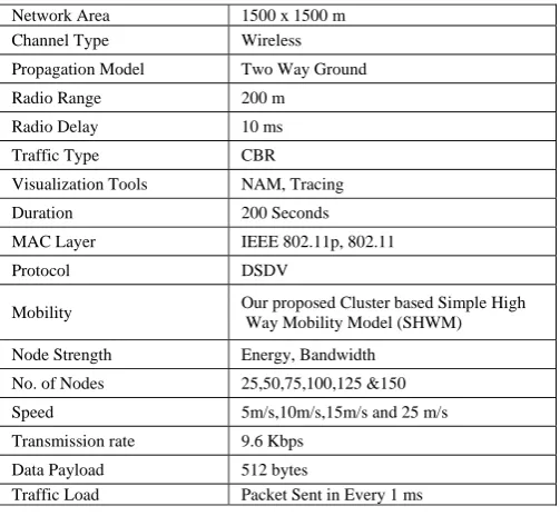
IMULATIONThe Cluster Based Simple Highway Model is proposed with a simulation using NS2.34. In Simple Highway Model the VANET is assumed as 1500*1500 meters of highway with bidirectional movements of vehicles. The SHWM model scenario is designed for various nodes. The proposed clustering technique divides the VANET area into a number of clusters. The IEEE 802.11p or 802.11 standards are included in the NS2.34 simulator to evaluate the performance of the proposed mobility model. The parameters used in NS2.34 VANET simulation is shown in Figure 3. The Traffic model Parameter for Node position and Node mobility are shown in Figure 4. The IEEE 802.11 & 802.11 p parameters used in NS2.34 simulation is shown in Figure 5 and Figure 6 respectively.
Figure 3: Critical parameters used in NS 2.34 VANET simulations
The NS2.34 version is the advanced version of NS-2. This version of NS-2 introduces two new modules: Mac802.11Ext and WirelessPhy-Ext. These two extensions are based on Mac802.11 and WirelessPhy. The frequency parameter Phy/WirelessPhyExt set freq_5.9e+9 or 5.85 GHz represents operation on DSRC band. The transmission power of each vehicle is set to Phy/WirelessPhyExt set Pt_ 5.0e-2. It creates a communication range of approximately 350 meters [13]. The PHY layer Parameters and MAC layer Parameters used in NS2 TCL file is shown in Figure 6 & 7 respectively. The NS2 simulation is visualized in NAM and Tracing Files. The NAM file can be used to view the output of the VANET simulation shown in Figure 9. The performance of the Mobility, Packet receiving time, Throughput, Broadcasting time and the Normalized routing overhead are measured by the values obtained from the NS2 trace file.
Figure 4: SHWM Node position and Node mobility parameter
Figure 5: IEEE 802.11 Parameters in TCL file
Network Area 1500 x 1500 m
Channel Type Wireless
Propagation Model Two Way Ground
Radio Range 200 m
Radio Delay 10 ms
Traffic Type CBR
Visualization Tools NAM, Tracing
Duration 200 Seconds
MAC Layer IEEE 802.11p, 802.11
Protocol DSDV
Mobility Our proposed Cluster based Simple High
Way Mobility Model (SHWM)
Node Strength Energy, Bandwidth
No. of Nodes 25,50,75,100,125 &150
Speed 5m/s,10m/s,15m/s and 25 m/s
Transmission rate 9.6 Kbps
Data Payload 512 bytes
Traffic Load Packet Sent in Every 1 ms
While(true)
{ If ( Any service request from a node in a cluster) {
The Algorithm Check the service in the local cluster data Base. If (Service present)
{ The procedure inform the sender that the service is present and also give the details about the service provider }
Else
{ Synchronize all the cluster heads and ensure that all the heads have latest service information }
Again the Algorithm check the cluster heads
If the service is not present, inform the node for service not present. } }
$node_(95) set Z_ 0.0000000 $node_(95) set Y_ 361.54 $node_(95) set X_ 1186.8 $node_(96) set Z_ 0.0000000 $node_(96) set Y_ 401.67 $node_(96) set X_ 1222.8 $node_(97) set Z_ 0.0000000 $node_(97) set Y_ 435.9 $node_(97) set X_ 1135.7
$ns_ at 2.5 "$node_(81) setdest 1250 179 10 $ns_ at 2.5 "$node_(82) setdest 1250 235.3 10 $ns_ at 2.5 "$node_(83) setdest 1200 218 10 $ns_ at 2.5 "$node_(84) setdest 1200 192.8 10 $ns_ at 2.5 "$node_(85) setdest 1200 280.1 10 $ns_ at 2.5 "$node_(86) setdest 10 447.7 10 $ns_ at 2.5 "$node_(87) setdest 10 365 10 $ns_ at 2.5 "$node_(88) setdest 10 434.3 10 $ns_ at 2.5 "$node_(89) setdest 10 431 10 $ns_ at 2.5 "$node_(90) setdest 10 369.8 10
set opt(chan) Channel/WirelessChannel ; # channel type set opt(prop) Propagation/TwoRayGround ;
# radio-propagation model
set opt(netif) Phy/WirelessPhy ; # network interface type set opt(mac) Mac/802_11 ; # MAC type
set opt(ifq) Queue/DropTail/PriQueue ;# interface queue type set opt(ll) LL ;# link layer type
set opt(ant) Antenna/OmniAntenna ; set opt(ifqlen) 50 ;# max packet in ifq
Figure 6: IEEE 802.11p Parameters in TCL file
Figure 7: PHY layer Parameters in TCL file
Figure 8: MAC layer Parameters in TCL file
Figure 9: Simple Highway Mobility Model NS2.34 simulation
VI.
E
XPERIMENTALA
NALYSISOFCBSHWMU
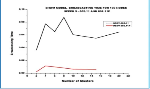
SING IEEE802.11&802.11Pi. Broadcasting time for the Cluster based SHWM model with DSDV and 802.11p & 802.11
The performance of the Cluster based SHWM model with 802.11p is compared with the same Cluster based SHWM model with 802.11 which is shown in figure 10. During emergency situations, critical information is sent to all cluster heads immediately. The Broadcasting time of packets sent to all cluster heads is estimated for various clusters. The proposed cluster based SHWM with 802.11p performs better than the SHWM with 802.11. When the number of clusters increases the Broadcasting time slightly increases in 802.11p and drastic change is observed in 802.11.
Figure 10: Cluster VS Broadcast Time (msec) for DSDV - 802.11p & 802.11 set opt(chan) Channel/WirelessChannel ; # channel type
set opt(prop) Propagation/TwoRayGround ; # radio-propagation model
set opt(netif) Phy/WirelessPhyExt; # network interface type set opt(mac) Mac/802_11Ext ;# MAC type
set opt(ifq) Queue/DropTail/PriQueue;# interface queue type set opt(ll) LL ;# link layer type
set opt(ant) Antenna/OmniAntenna set opt(ifqlen) 50 ;# max packet in ifq set opt(nn) 100 ;# number of mobilenodes set opt(adhocRouting) DSDV ;# routing protocol set opt(sc) "cbr1" ; # node movement file. set opt(x) 1500 ;# x coordinate of topology set opt(y) 1500 ;# y coordinate of topology set opt(seed) 0.0 ;# seed for random number gen set opt(stop) 250 ;# time to stop simulation
Phy/WirelessPhyExt set CSThresh_ 3.9810717055349694e-13
Phy/WirelessPhyExt set Pt_ 5.0e-2 Phy/WirelessPhyExt set freq_ 5.9e+9 Phy/WirelessPhyExt set noise_floor_ 1.26e-13 Phy/WirelessPhyExt set L_ 1.0 Phy/WirelessPhyExt set PowerMonitorThresh_ 3.981071705534985e-18
Phy/WirelessPhyExt set HeaderDuration_ 0.000040 Phy/WirelessPhyExt set BasicModulationScheme_ 0 Phy/WirelessPhyExt set PreambleCaptureSwitch_ 1 Phy/WirelessPhyExt set DataCaptureSwitch_ 1 Phy/WirelessPhyExt set SINR_PreambleCapture_ 3.1623 Phy/WirelessPhyExt set SINR_DataCapture_ 10.0 Phy/WirelessPhyExt set trace_dist_ 1e6 Phy/WirelessPhyExt set PHY_DBG_ 0
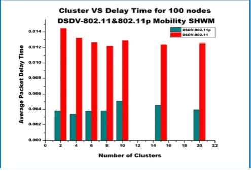
ii. Comparison of Packet delay time for 802.11p and 802.11
Packet delay time for node 100 with 802.11 and 802.11p is measured and the comparative delay time characteristic of 802.11 and 802.11p is noted. The delay time of the packet is low for 802.11p and it is high for 802.11. From the Figure 11, it is observed that the number of clusters between 6 and 10 gives optimal average delay time for 802.11p standard.
Figure 11: Cluster VS Delay Time (msec) for DSDV - 802.11p & 802.11
iii. Comparison of Packet receiving time for 802.11p and 802.11
The packet receiving time of the destination node is noticed for number of clusters with MAC 802.11 and 802.11p. This analytical work is repeated for varying number of clusters with different node speeds. It is observed that the packet receiving time is high for 802.11 and low for 802.11p. No major change is observed when the cluster size is increased.
Figure 12: Cluster VS Packet Receiving Time(msec) for Speed 5 DSDV – SHWM - 802.11p & 802.11
The Packet receiving time for node speed 5 and speed 10 are shown in Figure 12 and Figure 13 respectively.
Figure 13: Cluster VS Packet Receiving Time (msec) for Speed 10 DSDV – SHWM - 802.11p & 802.11
iv . Analytical study of Throughput value for 100 nodes with 802.11p & 802.11.
The performance of 802.11 & 802.11p in terms of throughput is shown in Figure 14. The graph describes the cluster VS throughput for the IEEE standard 802.11 & 802.11p. From the simulation result, it is noticed that when the number of cluster increases the throughput slightly decreases in the case of 802.11p and no major change is found in 802.11. It is also observed that the throughput for the cluster 6 to cluster 15 yields almost constant high value. From the above graph it is noted that 802.11p yields very high performance than 802.11.
v. Performance Analysis of Packet Delivery Ratio for node 100 using 802.11&802.11P
The Figure 15 presents the packet delivery ratio for various clusters with 802.11 & 802.11p standards. From this graph it is noted that when the number of clusters increases, the packet delivery ratio decreases slightly and yields optimal value between cluster 8 and cluster 15 in 802.11p. The packet delivery ratio is low for cluster below 10 and high for cluster above 10. Better performance of packet delivery ratio is observed for 802.11p.
Figure 15: Cluster VS Packet Delivery ratio for 100 nodes: DSDV – SHWM - 802.11p & 802.11
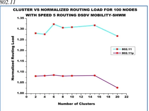
vi. Comparison of Normalized Routing Load for 802.11p and 802.11
Figure 16: Cluster VS Normalized Routing Load for 100 nodes: DSDV – SHWM - 802.11p & 802.11
The performance of the Normalized Routing Load for the cluster based SHWM model with standard 802.11 and 802.11p is shown in Figure 16. From the graph, the Normalized routing load is minimum for 802.11p and it out performs the standard 802.11.
VII.
C
ONCLUSIONThe IEEE is currently working on the new standard 802.11p, dedicated to Vehicular Communication which specifies physical (PHY) and Medium Access Control (MAC) protocol for Vehicle to Vehicle and Vehicle to Road Side Unit Communication. This paper discusses the comparative analysis of Cluster based Simple Highway Mobility model with standard 802.11p over the standard 802.11. The VANET MAC layer standard 802.11p is used to measure the Throughput, Packet delivery ratio, Broadcasting time, Normalized routing load for various clusters. These values are compared with the values obtained using 802.11. The simulation result gives that the proposed model with 802.11p has outperformed the result obtained using 802.11. Each VANET simulation has been done for 50 times and 50 various values are obtained for each node, cluster, 802.11p and 802.11 and the average value is computerized and presented in this paper.
R
EFERENCES[1] Saeed, R.A. Naemat, A. Bin Aris, A. Bin Awang, M.K. Access Network Technol., Malaysia “Design and evaluation of lightweight IEEE 802.11p-based TDMA MAC method for road side -to-vehicle communications” Advanced Communication Technology (ICACT), 2010 The 12th International Conference, 7-10 Feb. 2010 Volume : 2 ,On page(s): 1483 – 1488
[2] Alasmary, Waleed Zhuang, Weihua “The Mobility Impact in IEEE 802.11p Infrastructure less Vehicular Networks” Vehicular Technology Conference Fall (VTC 2010-Fall), 2010”,Issue Date : 6-9 Sept.2010,On pages 1-5, Canada.
[3] Shiann-Tsong Sheu Yen-Chieh Cheng Jung-Shyr Wu ,Taiwan “A Channel Access Scheme to Compromise Throughput and Fairness in IEEE 802.11p Multi-Rate/Multi-Channel Wireless Vehicular Networks” Vehicular Technology Conference (VTC 2010-Spring), 2010, Issue Date : 16-19 May 2010, On pages 1-5.
[4] Abusalah, L. Khokhar, A. Guizani, M. Univ” A survey of secure mobile Ad Hoc routing protocols”Communications Surveys & Tutorials, IEEE , Volume : 10 , Issue:4 On page(s): 78 - 93
[5] Ivan, I. Besnier, P. Crussiere, M. Drissi, M. Le Danvic, L. Huard, M. Lardjane, E. Technocentre Renault, Guyancourt, France “Physical layer performance analysis of V2V communications in high velocity context” Intelligent Transport Systems Telecommunications,(ITST),2009 9th International Conference, Oct 2009,Pages 409.
Networks”, 2007 Mobile Networking for Vehicular Environments, May 2007, Pages 91-96
[7] Jiang, D. Delgrossi, L. Mercedes-Benz R&D North America,” IEEE 802.11p: Towards an International Standard for Wireless Access in Vehicular Environments”, Vehicular Technology Conference,May-2008,Pages: 2036-2040.
[8] Brijesh Kadri Mohandas, Amiya Nayak, Kshirasagar Naik, Nishith Goel “ABSRP - A Service Discovery Approach for Vehicular Ad-Hoc Networks” page 1590-1594 IEE Asia-Pacific Services Computing Conference Dec 2008.
[9] A Survey and Qualitative Analysis of MAC Protocols for Vehicular Ad hoc NETworks
[10] Grafling, Sebastian Mahonen, Petri Riihijarvi, Janne “Performance evaluation of IEEE 1609 WAVE and IEEE 802.11p for vehicular communications” Ubiquitous and Future Networks (ICUFN), 2010 International Conference, Page 344-348.
[11] Eichler, S. Tech. Univ. Munchen, Munich” Performance Evaluation of the IEEE 802.11p WAVE Communication Standard” Vehicular Technology Conference, 2007, On page(s): 2199 - 2203
[12] Yuyi Luo Wei Zhang Yangqing Hu, Normal Univ., Shanghai, China “ A New Cluster Based Routing Protocol for VANET” 2010 Second International Conference April 2010, Page(s): 176 – 180, Volume : 1 Wuhan, Hubei
[13] Qi Chen ,Felix Schmidt Eisenlohr, DanielJiang, Marc Tollent-Moreno-Luca Delgrossi “Overhaul of ieee 802.11 modeling and simulation in ns-2” ACM New York, NY, USA -2007, Pages: 159 - 168.
[14] Hang Su Xi Zhang Texas A&M Univ., College Station Clustering-Based Multichannel MAC Protocols for QoS Provisionings Over Vehicular Ad Hoc Networks, Vehicular Technology, IEEE Transactions on Nov. 2007 -Volume : 56 , Issue:6 On page(s): 3309 – 3323