Proton Beam Multiplexer Developments for Multi-Target Operation at the
High-Brilliance Neutron Source HBS
MariusRimmler1,∗,JohannesBaggemann2,PaulDoege2,OlafFelden1,EricMauerhofer2,UlrichRücker2, HelmutSoltner3,RaimundTölle1,PaulZakalek2,RalfGebel1,ThomasGutberlet2, andThomasBrückel2
1Institut für Kernphysik (IKP-4), Forschungszentrum Jülich GmbH, 52425 Jülich, Germany
2Jülich Centre for Neutron Science (JCNS-2), Forschungszentrum Jülich GmbH, 52425 Jülich, Germany
3Zentralinstitut für Engineering, Elektronik und Analytik (ZEA-1), Forschungszentrum Jülich GmbH, 52425 Jülich, Germany
Abstract.The High-Brilliance neutron Source project (HBS) aims at developing a medium-flux accelerator-driven neutron source based on a 70 MeV, 100 mA proton accelerator. The concept intends to optimize the facility such that it provides high-brilliance neutron beams for instruments operating at different time struc-tures. This can be realized by three different target stations irradiated with different proton pulse sequences. The appropriate proton pulses will be distributed by a Multiplexer unit. In the following, we present the inte-gration of this Multiplexer with the HBS beam optics as well as ongoing developments of this unit and several components of the Multiplexer at the COSY facility in Jülich.
1 Introduction
Within the last decades, neutron scattering has proven to be a powerful tool for the observation of complex phenomena in condensed and soft matter science with impacts on innovations in our everyday life. Compact Accelerator-driven Neutron Sources (CANS) represent a promising new type of neutron sources to replace fading out reactors and to support future facilities as the European Spallation Source (ESS) [1]. In CANS, a primary proton or deuteron beam in the sub-100-MeV energy range impinges on a metal target generating neutrons via nuclear reactions. The High-Brilliance neutron Source project (HBS) aims to develop a pulsed medium-flux accelerator-driven neutron source facility based on a high current 70 MeV linear proton accelerator, optimized to deliver high brilliance neutron beams to a large variety of neutron instruments [2]. This requires a thorough adaption of the HBS layout to provide ideally suited neutron beam properties, e.g. energy resolution, energy spectrum and bandwidth for individual instruments simultaneously. Thus, it was decided to operate different target stations in parallel, each featuring a different group of neutron instruments with dedicated time structures. Corresponding adjustments of the primary proton beam pulsing scheme permit to efficiently generate neutrons serving the needs of the instruments.
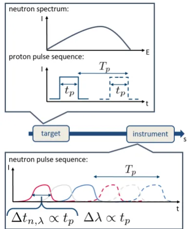
The correlation of proton and neutron pulse parameters is schematically shown in figure 1. The proton beam pulse lengthtpand frame lengthTpare correlated by a fixed duty cyclec=tp/Tp.
∗e-mail: m.rimmler@fz-juelich.de
Table 1.Comparative proton pulse sequences for three target stations at HBS.
Target Merit tp fp=1/Tp
1 high resolution short high
2 compromise medium medium
3 large bandwidth long low
Table 2.Proton pulse sequences for three target stations at HBS adjusted according to 2 % duty cycle.
Merit tp/µs fp/Hz
high resolution 52 384
compromise 208 96
large bandwidth 833 24
At the instrument, neutrons of the same energy or wavelengthλarrive in a certain time interval∆tn,λwhich is proportional to the primary proton pulse lengthtp. Thus the absolute wavelength uncertainty∆λof the neutrons is directly proportional to the proton beam pulse length.
For certain instruments one aims for a high resolution, i.e. minimum relative wavelength uncertainty∆λ/λ. For this reason it is favorable to use a short proton pulse length tp. With a fixed duty cycle, this corresponds to a short frame length Tp, i.e. high frequency f = 1/Tp. On the other hand, instruments that use a large bandwidth require a large frame lengthTpenabling neutrons with long wave-lengths to arrive at the instrument prior to neutrons with short wavelengths generated from the subsequent proton pulse. A trade-offbetween high resolution and bandwidth can be achieved by maintaining a target station that oper-ates at intermediate proton pulse and frame length. The compositions for the three target stations are summarized in table 1.
At the HBS such operation will be realized by intro-ducing three different pulse sequences to the primary pro-ton beam prior to acceleration. The different pulses will then be distributed to the according target stations by a de-vice calledMultiplexer.
2 Integration with HBS framework
The HBS will be operated with three different pulse se-quences as presented in table 2. The different frequencies are multiples of a base frequency (factor 4) such that a to-tal pulsing scheme can be created where lower frequency pulses will be always centered between two subsequent higher frequency pulses as shown in figure 2. In order to distribute the different pulses to the appropriate target station, it is planned to use a magnetic kicker - septum combination to pick the individual pulses and to send them into a different beamline. Hereby, a fast kicker magnet deflects the lower frequency components (green and blue components in figure 2) in between two subsequent higher frequency components (red in figure 2) oppositely. As a result, these deflected pulse components enter a certain region of the septum magnet which generates further de-flection of these pulse components. At the same time, the higher frequency proton pulses pass this Multiplexer unit
unperturbed. This method directly defines the minimum settling time of the kicker magnetic field at the beam po-sition to be the time between the shortest and the longest pulses, i.e. 859µs as shown in figure 2. In order to de-rive geometric constraints on the Multiplexer, i.e. kicker-septum combination, in terms of distances, deflection an-gles and gap heights of the magnets and thus necessary magnetic flux densities one has to analyze the beam dy-namics of the HBS facility. This can be done by dividing the beam transport line of the HBS facility from the accel-erator to the targets into three separate segments as shown in figure 3. It should be mentioned that this beam trans-port segments distribute over a ground and a top floor in order to irradiate the targets from the top. This is required to operate a target cooling concept based on liquid metal as thermal interface material.
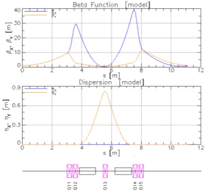
The facility is based on a 70 MeV, 100 mA proton LINAC with an approximate normalized rms emittance of x(y),norm,rms = 1 mm mrad, a momentum spread ∆p/p = 1% and beam Twiss parametersβx(y) =1 m,αx(y) = 0 at the matching point of the beam transport line. The proton beam is transported to a top floor at roughly 10 m height by the first segment which will feature two double-bend achromat units as shown in figure 6 deflecting into the x-y plane and into the x-z plane successively. The correspond-ing beam dynamics of these units, each consistcorrespond-ing of two quadrupole doublets in the beginning and in the end in or-der to control the beam Twiss parameters, a vertically fo-cusing quadrupole to compensate the dispersion and two 45◦sector bending magnets, are shown in figure 4. Since we employ bending of the beam in both horizontal and vertical degrees of freedom over the whole beam transport line, we aim for dispersion-free fully achromatic systems in order to avoid dispersion mixing. This works for the first segment according to figure 4 in combination with a point-to-point imaging of the beam size. Note that it was in general important to keep the betatron amplitudeβx(y) smaller than 40 m in order to utilize an inner beam tube diameter of 60 mm.
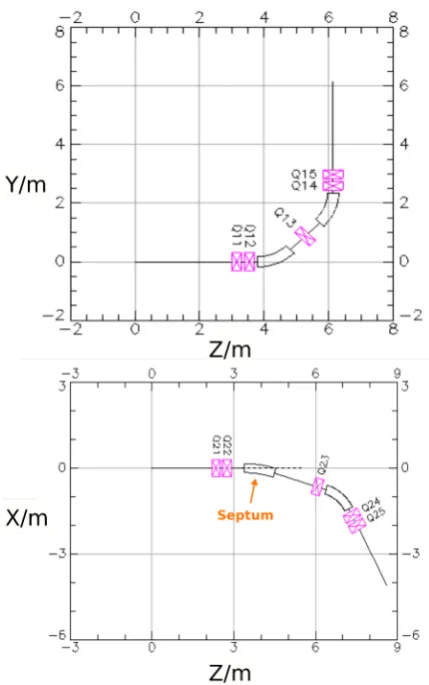
After beam transport to the top floor, segment two takes over, which comprises the Multiplexer device. Hence, this segment separates into three beam lines dur-ing propagation. Thereby the angular separation, which is governed by the septum magnet, is chosen such that the horizontal spacing allows the positioning of quadrupole magnets in the deflected beam lines after about 1 m drift length in order to treat dispersive effects emerging from the septum magnet.
Therefore, the deflection angle of the septum magnet was chosen to be 300 mrad. Together with an effective length of the septum of 1 m, this enables a horizontal sep-aration of neighboring beamlines of more than 450 mm after 1 m drift behind the septum. This allows the posi-tioning of a quadrupole at this distance in order to realize achromatic optics as shown in the bottom graph of figure 6. The floor plan shows a slightly asymmetric position of the centered quadrupole Q23 in a double-bend achromat composition with four additional quadrupoles, the septum magnet and a 45◦ sector bending magnet identical to the
Figure 2.Pulsing scheme of the primary proton beam of HBS. Red, green and blue pulses will be sent to the different neutron target stations. The lower part of the figure shows the time between subsequent pulses.
Figure 3. Layout of the HBS facility with three target stations. The neutron production will be driven by a 70 MeV, 100 mA proton LINAC as shown in the left part of the figure. The target stations are classified according to their proton pulse structures. The beam transport from the accelerator to the target station can be subdivided into three segments as shown in the figure. Segment one represents a achromatic system to transport the beam to the top floor. Segment two comprises the Multiplexer unit and segment three uses units from segment one in order to bend the beam towards the target station without dispersion.
Figure 4.Double-bend achromat systems as used in the first and third segment according to figure 3. This system will be used in three different orientations. One for bending up into the vertical plane and another one for bending back into the horizontal plane in segment one. Another one for bending down into the vertical plane and towards the target station in segment three.
Figure 6.Floor plan of double-bend achromat unit used in seg-ment one and three (top) and the second segseg-ment (bottom) ac-cording to beam dynamics shown in figure 4 and figure 5, respec-tively, and as introduced in figure 3. The dashed line in the lower graph indicates the beamline for unperturbed proton pulses.
beam dynamics calculations as shown in figure 5 prove a dispersionless point-to-point imaging for these optics. These beam optics will be used identically for the opposite deflection in the Multiplexer setup. The straight beamline transporting the unperturbed pulse sequences will only see the quadrupole magnets Q21 and Q22 of segment two. Fi-nally, after segment two, the three beamlines introduced by the Multiplexer will obtain a angular separation of more than 60◦ amongst each other. The spacing between the
target stations is therefore controlled by the length of the beamline from segment two to segment three (after each meter, one gains approximately 1 m additional horizon-tal separation), which can be either realized by a set of quadrupole triplets, doublets or FODO depending on the desired beam quality at the target.
At last, segment three reuses the double-bend achro-mat configuration utilized in segment one in all of its three beamlines to bend the beam vertically into the x-y plane in order to irradiate the targets from the top. By using quadrupole triplet configurations in the beamline prior to segment three, one would obtain a beam spot on the target with a diameter of 10 mm (as extracted from the LINAC)
Figure 7.Deflected orbit during propagation from kicker magnet to septum magnet of Multiplexer setup. 12 mrad angular deflec-tion at the kicker result in 18 mm offset at the septum posideflec-tion. Note the effect of feed-down dipolar kicks from the quadrupole magnets.
which can then be scanned by a kicker system within one pulse of minimum 52µs over a target area of 100 cm2.
The quadrupole magnets as planned are operated be-low 9 T/m gradients with 0.3 m effective length while the sector dipoles operate below 0.9 T on 1 m effective length. All dipoles can be connected in series while segment one and three use three quadrupole power converters together and segment two uses another three quadrupole power converters.
The lattice of the HBS beam transport from accel-erator to target now defines the design parameters for the Multiplexer. The beam size at the septum magnet is 6·σx=12 mm and 6·σy =35 mm according to figure 5. Aiming for a horizontal separation of the beam spots at the septum of 18 mm provides 6 mm distance between the beams in the beginning of the septum. This will be real-ized by a kicker magnet generating a 12 mrad kick, which is positioned 1.3 m in front of the septum, i.e. 0.1 m in front of the first horizontally focusing quadrupole of seg-ment two as shown in figure 7. The close positioning of the kicker with respect to this quadrupole helps reduce feed-down dipolar kicks from this quadrupole magnet on the deflected beam. For the given geometry, it is planned to use a kicker magnet with 0.5 m effective length and a mag-netic flux density of 30 mT.
The deflecting sectors of the three-field-septum magnet need to provide a magnetic flux density of 400 mT with an effective length of 1 m. The developments towards these magnets will be described in the following section.
The beam dynamics calculations in the present section have been carried out using theBmadlibrary [7]. Space charge effects were not taken into account at this stage of development. The overall beam size was considered to be six rms beam sizes 6·σx(y)which takes into account about 99.5 % of the total beam intensity.
3 Developments
setup at the cyclotron injector of the COSY (Cooler Synchrotron) facility, i.e. JULIC (Juelich light ion cyclotron). It provides 45 MeV H− [3] and 76 MeV D− [4] beams with a maximum current of 10µA in DC or pulsed mode. This accelerator serves as a test bench for multiple HBS related developments, e.g. target material selection and moderator performance tests. Furthermore, it is intended to build a CANS facility based on this accelerator which comprises the Multiplexer test unit during routine operation providing a second target station for fast neutrons [8].
The Multiplexer test unit will be scalable to HBS re-quirements which mainly manifests in an upgrade of the achievable magnetic flux densities of the magnets (kicker and three-field-septum magnet) due to an energy increase from 45 MeV to 70 MeV, corresponding to a factor of (Bρ)70 MeV/(Bρ)45 MeV=1.26, and appropriate material se-lection for enhanced radiation hardness of the magnets. Furthermore the power supply of the kicker magnet has to be chosen such that it provides the demanding HBS puls-ing scheme.
3.1 Evaluation of kicker magnet rise time for HBS Multiplexer
For further developments towards HBS Multiplexer oper-ation, one proceeds with the derived magnetic flux den-sities in section 2, i.e. 30 mT for the kicker magnet and 400 mT for the septum magnet. It is planned to use an array of permanent magnets for the septum as described in the following subsection. For the kicker magnet, how-ever, a high-performance power supply will be required to provide short rise times in order to distribute the pulses. Therefore, one needs to know precisely the specifications of such a power supply governed by the rise time of the current pulse delivered to the magnet. For this purpose, a simulation of eddy currents induced effects in the con-ducting walls of the beam pipe which predominantly limit the achievable rise times of the magnetic field seen by the beam was necessary.
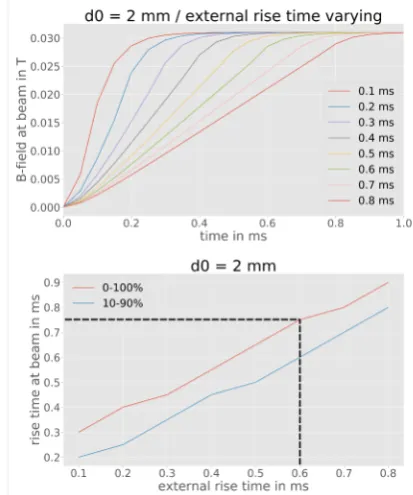
Studies on the effect of eddy-current induced delays from the stainless steel beam tube during current ramping are displayed in figure 8. From section 2 and figure 2 we know that the required rise time of the magnetic field seen by the beam must be less than 800µs. By taking into account a safety margin of roughly 50µs, the rise time of the kicker magnet itself must be below 600µs according to figure 8 in order to properly distribute the pulses to the target stations.
With the knowledge of the required magnetic excita-tion rise time of the magnet and the proposed beam tube diameter ofdID =60 mm one can now start to construct a magnet and power supply to provide 30 mT over on eff ec-tive length of 0.5 m.
3.2 Developments of Multiplexer test setup
The main features of the test setup will be a kicker magnet, previously employed at the COSY facility for injection,
Figure 8.Evaluation of magnetic flux density rise time at beam position in the kicker magnet of the Multiplexer setup gov-erned by eddy-current induced delays from the stainless steel beam tube withd0 = 2 mm wall thickness and inner diameter dID =60 mm. The top plot shows the magnetic flux density (y-component) time dependence at the beam position during ramp-ing of the current in the magnet with different magnet excitation rise times. The lower plot shows the rise time of the magnetic flux density at the beam position (0-100 % and 10-90 % rise time) versus different magnet excitation rise times as derived from the top plot. The dashed line indicates the magnet excitation rise time that yields 750µs rise time at the beam position. The mag-net is ramped up to 30 mT as described in section 2.
and an in-house developed septum magnet with three field regions as it may also be used in the HBS setup presented in section 2. The two magnets will be separated by 1.5 m along the direction of the beam line given by the spatial constraints of the building. In order to make further con-siderations on the design of the septum magnet, one has to determine the maximum deflection that can be provided by the kicker magnet.
The reused COSY injection kicker magnet is routinely operated with a 250 A power supply offering pulse rise, break and fall times matched to the COSY injection pro-cedure, i.e. 1 ms, 15 ms and 10 ms, respectively. The pulse parameters imply a slightly relaxed pulse sequence with respect to the HBS pulse sequence as shown in figure 2, which is however sufficient for a proof of principle. For fu-ture and more ambitious operation of the Multiplexer one could plan an upgrade or replacement of the power supply to offer appropriate pulse parameters as requested by the instruments at this HBS test facility.
Figure 9. FEM simulation and measurement of COSY kicker magnet model powered with 500 A. The upper figure shows the magnetic flux density distribution in the iron yoke of the magnet. The colorplot scale indicates that the magnetic flux density in the iron does not exceed 0.45 T which is well below saturation. The lower graph shows the simulation and the measurement of the magnetic flux density y-component in the centre of the magnet along the z-axis according to the coordinate system shown in the top figure.
spots at the septum. So far one would obtain 40 mm hori-zontal separation of the beam spots with 40 mm beam di-ameter, which turned out to be very challenging concern-ing the design of the septum magnet. Thus, it is planned to power the kicker magnet with an additional identical power supply in order to reach 500 A total current. To ensure the absence of saturation in the iron yoke of the magnet, an FEM simulation of the COSY injection kicker magnet model as shown in figure 9 was performed. From these simulations one sees that saturation during 500 A op-eration of the kicker magnet does not occur since the mag-netic flux density in the yoke is well below 2 T. Based on this simulation, it was proven experimentally that the in-tegrated vertical magnetic field of the kicker is raised to 42 mT·m. This enables a maximal horizontal separation of the beam spots at the position of the septum magnet of 77 mm facilitating the design of this magnet as described in the following paragraph.
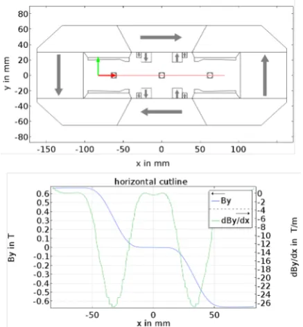
Figure 10 shows a cross-sectional view of the design of the septum magnet as it would be used in the Multi-plexer test setup. The test setup magnet will be based on NdFeB permanent magnets. The direction of magnetiza-tion is shown in figure 10 by grey arrows. The remanent magnetic flux density for the calculations was set to be 1.35 T.
The motivation to build a permanent-magnet based septum originated from the HBS proton beam parameters. Since the facility will be driven at a fixed design energy of
Figure 10. The top graph shows the 2D geometry of the new three-field-septum magnet used in the FEM simulation. The beam is normal to the image plane. The areas comprising gray arrows indicate the permanent magnets and their orientation of magnetization. All other enclosed areas which are mounted on the permanent magnets represent the iron yoke, i.e. carbon steel. The large centered area shows unoccupied space for the vacuum chamber including the three beam spots. The measured beam size at this position is 40 mm. The red line shows the segment which was used for the data in the lower graph. This plot shows the magnetic flux density y-component and its gradient versusx coordinate.
70 MeV, there is no necessity to tune the magnets which makes it economically favourable to use permanent mag-nets rather than a design based on electromagmag-nets [5]. Ad-ditionally it is aimed to built a so-called massless septum, i.e. no destructive elements in the aperture of the magnet, e.g. return conductors in current-driven septa. This low-ers the risk of radiation damage of the magnet due to a malfunction of the kicker magnet.
The dimensions of the three-field-septum magnet are presented in figure 10. They were adjusted to fit the beam size of 40 mm diameter at the future position of the sep-tum in the beamline. The separation of the outer beam spots to the centered unperturbed beam is 62.5 mm which can be achieved with 80 % of the maximum power of the upgraded kicker magnet.
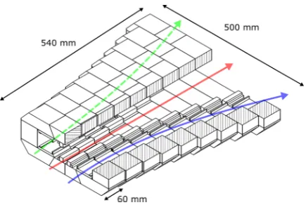
it-Figure 11. 3D layout of the septum magnet consisting of nine consecutive layers with 60 mm thickness, each. The horizon-tal apertures of these layers increase according to the trajectory of the deflected beams. The total length of the septum will be 540 mm with 500 mm width at the end. The colored arrows in-dicate the trajectories of proton beams with different pulse struc-tures as presented in figure 2.
erations including the positioning and shape of the perma-nent magnets and the pole face structure appropriate re-sults as shown in figure 10 were achieved.
The septum will be extruded by 0.54 m for the Multi-plexer test unit. A potential 3D layout of the septum mag-net is shown in figure 11. It consists of nine units with 60 mm depth appended onto each other. The horizontal size of this magnet increases in order to accommodate the trajectory of the beam. This design uses identical parts in each section and additional individual iron bricks which will be inserted in the center of the magnet units.
4 Conclusion
The HBS Multiplexer unit will be based on a kicker magnet and a three-field-septum magnet, in which the kicker magnet deflects different pulses into different di-rections such that the highest frequency pulse components will remain unperturbed. This requires a rise and fall time of the magnetic field at the beam position of less than 800µs. The break time varies between 208µs and 833µs depending on the pulse component that is going to be deflected. Taking into account eddy-current induced delays in the vacuum tube this calls for a rise time of the magnet which is below 600µs at 30 mT flat top field. The Multiplexer will be integrated with the HBS beam
transport line such that dispersion is suppressed. As to the conceptual design of the HBS Multiplexer unit it is planned to built a new septum magnet which features three different magnetic field regions - two regions of finite magnetic dipole field with opposite polarity in order to deflect the proton beam and one region which is supposed to remain field free during operation. Such a magnet will be developed at the COSY facility and integrated with a Multiplexer test unit. This magnet will be adapted to a 45 MeV H− beam and a significantly
larger beam size at the position of the septum due to the larger emittance at this facility compared to the HBS ion beam parameters. After successful operation of this test unit we will scale this magnet to smaller horizontal dimensions to match the smaller HBS ion beam size and elongate it longitudinally to 1 m length by increasing the number of consecutive layers to tackle the higher magnetic rigidity at 70 MeV. Furthermore, it is planned to select radiation hard permanent magnets of SmCo [6] with slightly lower remanent magnetic flux density for the HBS setup which requires additional lengthening of the magnet.
References
[1] ESFRI Physical Sciences and Engineering Strategy Working Group, Neutron Landscape Group, ESFRI ScriptaI(2016)
[2] U. Rücker et al.,The Jülich high-brilliance neutron source project, The European Physical Journal Plus 131, 19 (2016)
[3] W. Bräutigam et al., H- operation of the cyclotron JULIC as injector for the cooler synchrotron COSY-Jülich, IOP, 654 (1999)
[4] W. Bräutigam et al., Extraction of D- beams from the cyclotron JULIC for injection into the cooler syn-chrotron COSY, AIP600, 123 (2001)
[5] K. Halbach et al., Application of permanent magnets in accelerators and electron storage rings, Journal of Applied Physics57, 3605 (1985)
[6] C.H. Chen, J. Talnagi, J. Liu, et al., The effect of neu-tron irradiation on Nd-Fe-B and Sm2Co17-Based high-temperature magnets, IEEE Trans. Magn.41, 10 (2005) [7] https://www.classe.cornell.edu/bmad/