59
EXPERIMENTAL ANALYSIS OF TURBULENT
FLOW HEAT TRANSFER IN A RECTANGULAR
DUCT WITH AND WITHOUT CONTINUOUS
AND DISCRETE V-SHAPED INTERNAL RIBS
Pankaj N. Shrirao
1, Rahul M. Sherekar
2, Sachin V. Bhalerao
3 1 2 3Department of Mechanical Engineering
1 2 3Jawaharlal Darda Institute of Engg. & Technology
M.I.D.C. Area, Lohara, Yavatmal-445001 Maharashtra, India
1
[email protected]
ABSTARCT:
In this present work, Experiments were performed to collect heat transfer and friction data for forced convection flow of air in rectangular duct with and without internal ribs. The analysis was conducted within the range of Reynolds number from 3000 to 18000. The horizontal rectangular duct was subjected to constant and uniform heat flux. Experimental results for this configuration are reported for three different channels viz., smooth rectangular duct, rectangular duct with continuous V- shaped ribs and rectangular duct with discrete V- shaped ribs. The effects of internal ribs on the heat transfer coefficient and friction factor are compared with the result of smooth duct under similar flow conditions. Experimental results show that the local Nusselt number distribution is strongly depended on the position, orientation, and geometry of the ribs. The friction factor ratio goes up with an increase in the Reynolds number, but its value depends on the arrangement of ribs. The results also show that the discrete V- shaped ribs produce overall less heat transfer enhancement than the continuous V- shaped ribs. However, the increased heat transfer enhancement in the continuous V- shaped ribs came at the cost of an increased pressure penalty.
Keywords: Heat transfer augmentation; Forced convection heat transfer; Internal ribs; Rectangular duct.
.
1. INTRODUCTION
60
Stanton number could be enhanced up to 5.8 times with friction factor increase of 6.5 fold compared to plain tube. D. Angirasa [3] performed experiments that proved augmentation of heat transfer by using metallic fibrous materials with two different porosities namely 97% and 93%. The experiments were carried out for different Reynolds numbers (17,000-29,000) and power inputs (3.7 and 9.2 W). The improvement in the average Nusselt number was about 3-6 times in comparison with the case when no porous material was used. Fu et al. [4] experimentally demonstrated that a channel filled with high conductivity porous material subjected to oscillating flow is a new and effective method of cooling electronic devices. The experimental investigations of Hsieh and Liu [5] reported that Nusselt numbers were between four and two times the bare values at low Re and high Re respectively. Bogdan and Abdulmajeed et al. [6] numerically investigated the effect of metallic porous materials, inserted in a pipe, on the rate of heat transfer. The pipe was subjected to a constant and uniform heat flux. The effects of porosity, porous material diameter and thermal conductivity as well as Reynolds number on the heat transfer rate and pressure drop were investigated. The results were compared with the clear flow case where no porous material was used. The results obtained lead to the conclusion that higher heat transfer rates can be achieved using porous inserts at the expense of a reasonable pressure drop. Smith et. al. [7] investigated the heat transfer enhancement and pressure loss by insertion of single twisted tape, full length dual and regularly spaced dual twisted tapes as swirl generators in round tube under axially uniform wall heat flux conditions. Chinaruk Thianpong et.al. [8] Experimentally investigated the friction and compound heat transfer behavior in dimpled tube fitted with twisted tape swirl generator for a fully developed flow for Reynolds number in the range of 12000 to 44000. Whitham [9] studied heat transfer enhancement by means of a twisted tape insert way back at the end of the nineteenth century. Date and Singham [10] numerically investigated heat transfer enhancement in laminar, viscous liquid flows in a tube with a uniform heat flux boundary condition. They idealized the flow conditions by assuming zero tape thickness, but the twist and fin effects of the twisted tape were included in their analysis. Saha et al. [11] have shown that, for a constant heat flux boundary condition, regularly spaced twisted tape elements do not perform better than full-length twisted tape because the swirl breaks down in-between the spacing of a regularly twisted tape. Rao and Sastri [12], while working with a rotating tube with a twisted tape insert, observed that the enhancement of heat transfer offsets the rise in the friction factor owing to rotation. Sivashanmugam and Sundaram [13] and Agarwal and Rao [14] studied the thermohydraulic characteristics of tape-generated swirl flow. Peterson et al. [15] experimented with high-pressure (8–16 MPa) water as the test liquid in turbulent flow with low heat fluxes and low wall–fluid temperature differences typical of a liquid–liquid heat exchanger.
The present experimental study investigates the increase in the heat transfer rate in a rectangular duct heated with a constant uniform heat flux with air flowing inside it using continuous and discrete V-shaped internal ribs of same geometrical configuration. The present work has been carried out with turbulent flow (Re number range of 3,000-18,000) as most of the flow problems in industrial heat exchangers involve turbulent flow region.
2. EXPERIMENTAL WORK
2.1. Experimental Setup
61
voltmeter, ammeter and temperature indicator. The circuit was designed for a load voltage of 0-220 V; with a maximum current of 10 A. Difference in the levels of manometer fluid represents the variations in the flow rate of air. The velocity of airflow in the tube is measured with the help of orifice plate and the water manometer fitted on board.
2.2 Procedure
[image:3.595.136.441.331.435.2]Air was made to flow though the test duct by means of blower motor. A heat input of 60 W was given to the nichrome heating wire wound on the test duct by adjusting the dimmer stat. The test duct was insulated in order to avoid the loss of heat energy to the surrounding. Thermocouples 2 to 4 were fixed on the test surface and thermocouples 1 and 5 were fixed inside the pipe. The readings of the thermocouples were observed every 5 minutes until the steady state condition was achieved. Under steady state condition, the readings of all the five thermocouples were recorded. The experiments were repeated for different channels viz., rectangular duct with continuous V- shaped ribs and rectangular duct with discrete V- shaped ribs. The fluid properties were calculated as the average between the inlet and the outlet bulk temperature. Experiments were carried out at constant heat input and constant mass flow rate, for all the three test ducts.
Fig. 1 Experimental Set-up
[image:3.595.106.473.504.698.2]62
3. DATA REDUCTION
The data reduction of the measured results is summarized in the following procedures:
The heat transfer coefficient for the “i” wall segment was calculated using the net heat input to the wall; the wall temperature and the bulk mean temperature as
hi= qi / As,i (Tw,i - Tb,i) (1) The actual heat going into the duct is given by the amount of power supplied which is the product of voltage applied and the current flowing in the circuit minus the amount of heat loss from each plate. The flexible heaters were assumed to supply uniform heat to all the test ducts. The heat loss from the test section to the surrounding was calculated experimentally by conducting a no-flow condition. The heat loss to the surrounding was found to vary between 5-15% for various Reynolds number. The major heat loss was found to occur through the thick wired copper thermocouples installed in each wall segment.
The Nusselt number was normalized using the Nusselt number correlation for a fully developed flow in a smooth duct. The relative uncertainty on Nusselt number was found to be 5%.
Nu / Nuo = (hDh/ K) [0.023 Re 0.8 Pr 0.4] (2) All the temperatures were measured using the thermocouples. The bulk mean air temperature at the inlet and the exit was measured using the thermocouples and the bulk mean temperature at the end of each test duct was calculated using the formula given by
Tb,out = Tb,in + q/ (m Cp ) (3)
The pressure drop measured with a micro-manometer across the test section, was used to calculate the friction factor. The relation between pressure drop and friction factor is given by
(4)
The fiction factor is normalized by Gnielinski equation
fo =[0.79 ln (ReDh)- 1.64] -2
(5)
The correlation for thermal performance is given by
TP = (Nu / Nuo)/ (f/fo) 1/3 (6)
4. RESULT AND DISCUSSION
Heat Transfer Distribution for smooth rectangular duct, rectangular duct with continuous V- shaped ribs and rectangular duct with discrete V- shaped ribs:
63
effective removal of heat. However, the Nusselt number ratio, which is obtained by normalizing the average Nusselt number with the fully developed turbulent flow in smooth test tube correlated by Dittus Boelter, was found to decrease as shown in Fig 3.
In the case of smooth test duct the variation of Nusselt number ratio with increasing Reynolds number is very small as there is no flow separation and reattachments in this case and so Reynolds number does not have any effect on the heat transfer augmentation. Therefore, the Nusselt number ratio for all four Reynolds number follow a similar trend. The Nusselt number ratio was found to be highest for the lowest Reynolds number and lowest for the highest Reynolds number. It was found to vary between 2.15 and 1.1 along the axial direction.
0 0.5 1 1.5 2 2.5
1 2 3 4
X/Dh N u /N u o 5000 8000 12500 15600
Fig.3 Effect of Reynolds Number on Heat Transfer Distribution for Smooth Rectangular duct
The heat transfer augmentation for rectangular duct with continuous V- shaped ribs was found to increase by factor of 1.7 to 2.1 in comparison to the smooth rectangular duct and by a factor of 1.06 to 1.20 in comparison to the rectangular duct with discrete V- shaped ribs. The increase in heat transfer coefficient is attributed to the induction of cross-stream secondary flow, which results in better turbulent mixing.
0 0.5 1 1.5 2 2.5 3 3.5 4 4.5
1 2 3 4
X/Dh N u /N u o 5000 8000 12500 15600
64
0 0.5 1 1.5 2 2.5 3 3.5 4
1 2 3 4
X/Dh
N
u
/N
u
o 5000
8000
12500
[image:6.595.86.511.158.373.2]15600
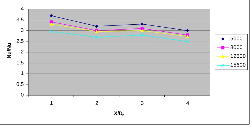
Fig.5 Effect of Reynolds Number on Heat Transfer Distribution for Rectangular duct with discrete V- shaped ribs
Friction Factor Characteristics for smooth rectangular duct, rectangular duct with continuous V- shaped ribs and rectangular duct with discrete V- shaped ribs:
The friction factor ratio was found to increase with increase in Reynolds number due to the resistance offered to the flow of fluid. The heat transverse augmentation was found to vary between 1.5-2 for the rectangular duct with discrete V- shaped ribs and 2-2.5 for the rectangular duct with continuous V- shaped ribs. This enhancement in both the cases was accompanied by pressure drop penalty of 1.5 to 3 on the rectangular duct with discrete V- shaped ribs and 3 to 4 on the rectangular duct with continuous V- shaped ribs. The rectangular duct with continuous V- shaped ribs produced 20 % to 40% higher pressure drop when compared to the rectangular duct with discrete V- shaped ribs for the complete range of Reynolds number investigated.
[image:6.595.81.517.545.724.2]65
Thermal Performance:
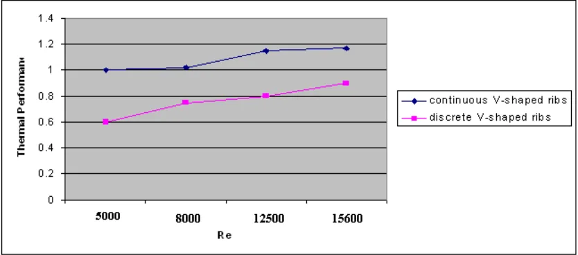
[image:7.595.90.507.248.432.2]Thermal performance for the plate with internal ribs is drawn as below in fig. 7, shows that thermal performance is increasing with increase in Reynolds number. But the thermal performance for rectangular duct with discrete V- shaped ribs is poor as compared to the rectangular duct with continuous V- shaped ribs. This is due more turbulence and strong vortex formation in rectangular duct with continuous V- shaped ribs. Also it reflects that thermal performance of rectangular duct with continuous V- shaped ribs is more than one which means applying continuous V- shaped ribs is beneficial to increase heat transfer enhancement.
Fig. 7 Variation of Thermal Performance with Reynolds Number for Various Configurations
Acknowledgments
We are thankful to the Hon. Principal Dr. A.W. Kolhatkar and Head of Department Dr. A. B. Borade, Jawaharalal Darda Institute of Engineering and Technology, Yavatmal, Maharashtra, India for providing Mechanical Engineering Research Laboratory for Experimentation study and their moral support.
References
[1] M. Sozen and T M. Kuzay (1996), “Enhanced heat transfer in round tubes with porous inserts”, International Journal Heat and Fluid Flow, Vol. 17, pp.124-129
[2] Q. Liao and M.D. Xin (2000), “Augmentation of convective heat transfer inside tubes with three-dimensional internal extended surfaces and twisted-tape inserts”, Chemical Engineering Journal, Vol. 78, pp. 95-105
[3] D. Angirasa (2001), “Experimental investigation of forced convection heat transfer augmentation with metallic porous materials”, International Journal of Heat Mass Transfer, pp. 919-922
[4] H.L. Fu, K.C. Leong, X.Y. Huang and C.Y. Liu (2001), “An experimental study of heat transfer of a porous channel subjected to oscillating flow”, ASME Journal of Heat Transfer, Vol. 123, pp.162-170.
[5] S.S Hsieh, M.H. Liu, H.H. Tsai (2003), “Turbulent heat transfer and flow characteristic in a horizontal circular tube with strip-type inserts part-II (heat transfer)”, International Journal of Heat and Mass Transfer, Vol. 46, pp.837-849.
[6] B.I. Pavel and A.A. Mohamad (2004), “ An experimental and numerical study on heat transfer enhancement for gas heat exchangers fitted with porous media”, International Journal of Heat and Mass Transfer, Vol. 47, pp.4939-4952.
66
[8] Chinaruk Thianpong, Petpices Eiamsa-ard, Khwanchit Wongcharee and Smith Eiamsaard (2009), Compound heat transfer enhancement of a dimpled tube with a twisted tape swirl generator, International Communications in Heat and Mass Heat and
Mass Transfer, Vol. 36, pp. 698-704.
[9] Whitham, J. M (1896), The effects of retarders in fire tubes of steam boilers, Street Railway, Vol. 12(6), pp. 374.
[10] Date, A. W. and Singham, J. R. (1972), “Numerical prediction of friction and heat transfer characteristics of fully developed laminar flow in tubes containing twisted tapes”, Trans. ASME, Journal of Heat Transfer, Vol. 17, pp. 72
[11] S.K.Saha, U.N.Gaitonde and A.W. Date (1989), “Heat transfer and pressure drop characteristics of laminar flow in a circular tube fitted with regularly spaced twisted-tape elements”, Journal of Exp. Thermal Fluid Sci., Vol. 2, pp.310-322.
[12] Rao, M. M. and Sastri, V. M. K. (1995), “Experimental investigation for fluid flow and heat transfer in a rotating tube twisted tape inserts”, International Journal of Heat and Mass Transfer, Vol.16, pp.19–28.
[13] Sivashanmugam, P. and Suresh, S. (2007), “Experimental studies on heat transfer and friction factor characteristics of turbulent flow through a circular tube fitted with regularly spaced helical screw tape inserts”, Experimental Thermal and Fluid Science, Vol. 31, pp. 301-308.
[14] Agarwal, S. K. and Raja Rao, M. (1996), “Heat transfer augmentation for flow of viscous liquid in circular tubes using twisted tape inserts”, International Journal of Heat Mass Transfer, Vol. 99, pp.3547–3557.