HIGH AIR-EFFICIENCY INSULATION
THESIS
BY
F. W. MAXSTA'!Yr
In Partial Fulfillment of the Requirements tor the
Degree of
DOCTOR OF PHILOSOPHY
ABSTRACT
The subject is introduced by a review of some of the work of others which seems not to be generally known. Its beginnlng ls traced· t.o the appl1oa:t1on of three we11
known principles of eleotrostat1cs1 which are presented in detail. Examples of the limitations of elementary
electro-statio theory are set forth.
Taken in the order of their influence, each of ten or more factors which control the arc-over strength of solid insulators 1n air are analyzed, with experimental data accompanying each analysis.
A
new means of increasing the arc-over strength of an insulator is suggested and experimental results for a tevr samples are presented.T1me d1d not perm.1~ extending the 1nvest1gat1on
to the arc-over strength of insulators under oil, but many of the factors herein analyzed for insulators in ai~ apply
almost direct.ly to oil.
A mechanism of arc-over of solids in air is
suggested although a great deal more data will be necessary
to justtfy lt.
INTRODUOTION
Late in 1906, the highest commercial transmission
voltage (errect1ve value, line to line) leaped from 70 kv.
to
120
ltv. , a daring adventure on the part of engineersand their backers. It was made possible by the develope-ment of the Hewlett1 "suspension" insulator for overhead transmission lines.
The next big step in the ~mprovement of insulation came as a result of ·the pressure put upon designers of
indoor high voltage apparatus to produce terminal bushings (then the weakest link in the chain) of rating comparable
with transmission line insulation~ These terminal bushings
are the insulators through which conductors enter the iron tank• of transformers and switches or enter the roofs of
buildings.
Fortescue2 by applying Ma:xwell's3 potential functions to the calculation of electric flux d1stribu-tion, and using a good deal of judgement based on correct electrostatic principles, designed a transformer terminal bushing which withstood upwards of half a million volts effective value, He and Farnsworth also constructed and
1. E. M.
Hewlett,Trans. AIEE 26 (2) 1259, (1907).
2, C. L. Fortescue
&
s.
w.
Farnsworth, Trans. AIEE 32(1)893 (1913) also
C.L.
Fortescue Trans.AIEE 32 (1)907(1913).
3. Jam.es Clerk Maxwell "A Treatise on Electricity & Magnetism" Oxford.
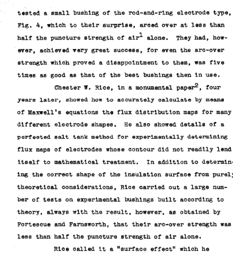
tested a small bushing of the rod-and-ring electrode type, Fig.
4,
which to their surprise, arced over at lees than half the puncture strength of air1 alone. They had, how-. ever, achieved Tery great success; for even the arc-over strength which proved a disappointment to them, was five times as good as that of the beet bushings then in use.Chester
w.
Rice, in a monumental paper2 , four years later, showed how to accurately oaloulate by means of Maxwell's equations the flux distribution maps for many different electrode shapes. He also showed details of a perfected salt tank method for experimentally determining flux maps of electrodes whose contour did not readily lend itself to mathematical treatment. In addition to determ1n-1ng the correct shape of the insulation surface from purely theoretical considerations, Rice carried out a large num-ber of tests on experimental bushings built according to theory, always with the result. however. as obtained by Fortescue and Farnsworth, that their arc-over strength was less than half the puncture strength of air alone.Rice called it a Hsurfaee effect" which he
attempted to test more thoroughly by placing right circular cyl1nf.'l.ers of various insulating materials in the homogen-1ous field between two parallel flat electrodes.
[image:4.614.69.526.50.546.2]It was not until Schwaiger1 of Karlsruhe described his arc-over tests on porcelain that the important hum.141ty factor affecting this surface phenomanon was presented. The relative humidity of the surrounding atmosphere determines to a larger extent than any other raotor excepting atmos-pheric pressure, the arc-over strength of a given surface.
In 1926-27,
GeorgeK.
s.
Diamos
and Wm.A.
Lewis2
began work on circular cylinders or aort glass, hard rubber,
porcelain, and Bakelite at California Institute of Tech-nology, testing the arc-over voltage in terms of atmos-pheric humidity and also the time required for the sample to come to equilibrium with the surrounding atmosphere after it had been dried in an oven for several hours at 90°
o.
The following year, J. W. Thatcher3 continued the tests on similar materials in constant humidity
atmos-pheres and at temperatures from 40°C to 6000 adding Pyrex
to the list of substances tested.
The present work was begun in the fall of 1928
4
and has been carried on with the assistance of E.E.K1nney 11. A. Sohwaiger, E.T.Z. 26 875 (June 29, 1922).
2. George K.S.Diamos & W.A.Lew1s, Master's Thesis 1927 on file 1n the Main Library,· Calif. Institute of Tech. 3. J.W.Thatcher,Master'a Thesis 1930 on file 1n Main
Library C.I.T.
4. E.E.Kinney, Master's Thesis 1930 on file 1n Main Lib-rary C.I.T.
who was especially concerned with surface resistance
measurements, and K. M. W1lson1 who has studied the effect
of changes in atmospheric pressure and the effect of extremely dry atmospheres, below one per cent r~lative
humidity. Tests have been carried out on the arc-over voltages of right oi~cular cylinders of the material, in homogenious fields between flat parallel plates. A few
experiments were conducted on slender fibres of Fyrex and
of Quartz, also on strips of paper, cloth and Cellophane and one series of readings on a stack of squares
or
paper. All of the arrangements were in homogenloue f1elde parallel to the surface of the specimen.ELEMENTARY ELEX'lTROSTATIC THEORY FARADOID-PRINCI!LE
If two different d1electrios are placed between flat electrodes A and B, F1g. l, tne ~espect1ve th1cJm.esses of these d1eleotr1os being d1 and d2 the total voltage V between the electrodes w111 be shared by the dielectrics as follows:
Ki"'
i,*
v1K2 di
v
~ A ~ • Kl d2+ K2dl
I
I I
II
I
IllTl
I
I
I
I
I
I
I I
l
:1
!
V2K1 d2
v
I
I
II
I•
Kid2+K2d1I :
I
II I
II
I I 2I
'
I
1i
~I
I
I
I
gl :...!L.
lt2v
~
>
d1 tti:d2+
K2dlt<2.
=SDIELECTRICS IN SERIES S1K1
=
SiC2 F1g. 1Since the denominators of the
v
1 and V2 equations are the same, it is obvious that the dielectric of lower permittivity (specific inductive capacity) perhaps air, will be subjected to the greater stress. Assume, -forexample, two electrodes 1 cm. apart, having impressed be-tween them 15 k:v. effect1ve1 • If air alone fills the gap, the stress on the air is 15 kv. per cm. Next, place 0.8 om. plate of glass K •
5.
in the gap, leaving 0.2 cm.of
air. Letting g1 represent the stress (voltage gradient) on the1. Ettect1ve values will be used throughout this presentation. They correspond to the kind of values ordinarily indicated by voltmeters and are therefore considered more logical than orest values.
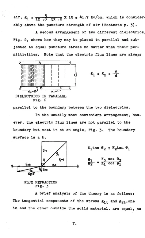
air, g1
=
lX .~ 5X •2 X 15=
41.7 kv/cm. which is consider-ably above the punoture strength of air (Footnote p.3).
A second arrangement of two different dielectrics, Fig. 2, shows how they may be placed in parallel and
sub-jeoted to equal puncture stress no matter what their per-mittiv1t1es. Note that the electric flux lines are always
K,=l
DIELECTRICS IN PARALLEL
F1g. 2
parallel to the boundary between the two dielectrics. In the usually most convenient arrangement, how-ever, the electric flux lines are not parallel to the boundary but meet it at an angle, Fig. 3. The boundary surface is a b.
FLUX REFRACTION
F1g. 3
[image:8.613.50.523.20.792.2]in the simple case, Fig. 2. They cannot be otherwise, for there is no discontinuity in that direction. The normal components of the stress gln and g2n, on the other hand, have the ratio K2 to Ki as in Fig. 1 because of passing
ao~roea a boundary between two different mater1a1s.
Combin-ing the vectors, resultants g1 and g2 which, obviously, are not continuous, are obtained and g2 suffers a. refraction, bending away from the normal. Vectors
s
1 and
s
2 represent, in direction the path of the electric flux lines and, in magnitude the voltage gradient in ea.ch dielectric.It will be evident upon examination of the vectors that Figsi. 1 and 2 are the limiting oases, Fig. 2 being the desirable one in which the gradient is independent of the presence of the solid dielectric. The above reasoning lead Fortescuel to the enormous improvement of five to one over his ooritemporaries in the use of solid insulation in com-bination with air. The principle just outlined in which the solid insulator is ma.de to conform in shape to the flux lines so there will be no refraction, is known as the Faradoid
Principle and insulators so designed are called Farado1d insulator.a.
DISRUPTIVE STRENGTH OF AIR IN OONTAOT
WITH A SOLID DIELEOTRIC--SURFAOE EFFECT
Fortescue's failure to attain perfeot1on will
1. Loe cit. (1913)
be appreciated when one recalls that hie rod-and-ring bushing, Fig. 4, made of shellac and other gums with whiting filler, arced over at 9.1 kY. effective per cm. instead of at the desired value, the disruptive strength
ROD-AND-RING BUSHING Fig.
4
of air, 20 ltv. per cm. An even more disquieting experimental result has been presented by Weed1 who was
exper-imenting with insulator bushings about the same time. Weed built several
bushings by turning hard
rubber in the lathe. One of them was a copy of Fortescue's theoretical form, Fig. 4,
WEED MODIFICATION Fig. 5
and another was somewhat similar but with two zones flattened off, Fig.
5.
The first arced over at52.5
k:v'.that the better bushing does not conform to the theoretioal
contour, whereaa the other one does.
R1ce1• with another theoretically designed bueh-. ing of glazed poroela1n, obtained an arc-over ~trength of
7.1
kv. effective per cm. scarcely more than one third of the ideal value. Seeing that some experiments of a more fundamental nature should be made, he proceeded to test a great variaty of· insulating ma.teriA.ls in the f<'lrm of right circular cylinders in homogenious f 1elds parallel to the insulation surface, an arrangement electrostatlcally identi-cal with Fig. 2. At best,only about 85 per cent of the ideal arc-over strength was obtained. Rice advanced two explan-ations. The first was imperfect contact between electrodeand specimen, causing premature corona formation
and
conse-quent early arc-over. The second was contamination of the insulator surface by moisture from the atmosphere.
Schwa1ger2 made extensive tests on porcelain and found a definite relation between relative humidity of the air and the arc-over strength of the insulator. One of his curves, Fig. 6. will illustrate the point.
He further round that certain kinds of 1nhomo-geniety of the electric field resulted in greater arc-over strength of the specimen. Lastly, he showed the effect of
1. Loe. cit. (1917).
2. Loe cit. (1922) also A. Bchwaiger,Elektr1eche Festigkeits-lehre, 2nd Ed. 1925 Springer p. 164-173.
"
' \ \ \ BI'
\6 \ ' I
1q
\
\
12 . '
,,
10 '
8
b
l'O ~C.IL "''f'I
-
,.., .. .... 6 C11tR j ~·c.
....
,
! ... r--t.!.._c~'
"I'-.
... t.!.9rM
~-N•
--r
--
-the length of sample and pointed out a rather close analogy between the aro-over oharaeter1stios of a sol1d and the disruptive strengtih
or
a.1r.fhe foregoing
4 ' - r - · experiments have been
re-z
~ ff ~ ~ ~
PER C.11'.l'IT Rltl.ATIVll HUMilllTV
ARC-OVER STRENGTH
Fig. 6 lSd\waU:Jer)
viewed at some length
be-cause they show that the elementary electrostatic theor¥ 1s totally inade-quate to account for many of the complex factors involved.
It la at this point the work at Oaliforn1a Insti-tute begins and no less than ten important factors which
influence the disruptive strength of air when in contact w1 th a solid dielectric have been investigated. These w111 be presented in the order of importance and the approximate extent of th•!r influence estimated in each case.
REt.iATIVE HUMIDITY OF THE :ENVIRONMENT
When an insulator whose entire surface not 1n
oontaot with the electrodes 1e plaoed parallel to the flux lines in a homogenious field, the effect of moisture
voltage o·r the insulation to a value below the disruptive strength of the air alone. Why this should be the case has not been proven but an explanation is suggested in the
APPENDIX.
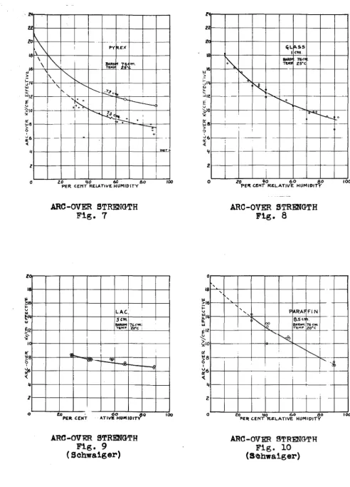
Figs.6, 7, 8, 9 and
10 show characteristic curves obtained for five different substances-. Many others have been tested but all (with the exceptions of fused quartz fibres and untreated "Bondtt paper) show characteristics similar to thOBe shown. The arc-over voltages, at ordinary humidities, for allof the well known insulating materials will be found to be approximately 1/2 to 1/3 the values corresponding to the strength of the air alone when homo-genious field conditions exist.It is possible to obtain the full strength of the air if the insulation is absolutely dry (for example, having been baked for several hours in a vacuum) and is
surrounded by air containing no moisture.
To demonstrate this fact about which there was some doubt, Mr. Wilson1 and I assembled a vacuum system, Fig. 11, consisting of a Pyrex tube, with a mercury-sealed
joint at the bottom, 1nto which could be placed two accur-ately flat and polished copper electrodes 4.5 cm. diam.
and a test sample whose maximum dimensions should be 2.6 cm. diameter X 1.0 cm. long, the electrodes being enough larger than the sample to insure a distribution of field parallel
1. Loe. cit.
zz
o'
8\\
\
6 \
~ z lJ ~ w6 ). 0 ' fi6 <( 4 z 0 z ·~ ,_ 14 12 I 8 4 2 0 -- - - · -· -~
! PY REX
""''
JM~~ fl 76 ..,.,,
-· TEI'! .. .zs• \ I~~
\.
'
I' ' ... ['...__ ..;!,.7c~....
.
.
--0..! •I~
r---.
I ... ~-=
""'·
.
Ii...-..:.
.
·-·
-:-~ -
-t.O 'tO 60 80 PER CENT RELATIVE HUMIDITY
ARO-OVER STRENGTH
Fig.
7
I
LAC,
jClll.
_
...
7G<m.I
T&M~ 2o"C I
i
Cl
'6'
-
,,.to .
PEil CENT A. TIVI! HUM 10 IT'( 60 60
ARC-OVER STRENGTH
Fig.
9
( Schws.iger)
..
,.. -I ··--· I I 100 v 100 : zz -~ w ). 18 16 1-•J llJ ....1 4
-
"-"1 I t -0 8 6 't 2 0 0 ' 18 '
~L IA.SS I Ctn.
~
BARO• . 76<>.TUii. Z5'C
·~
---~ r--...
- · - ...
K r-...
o--t. ..._
.
,_ ! I I I ! · - - · · I i20 ¥0 60 80
'PEil C!lNi R.l!:LATIVE HUMIDITY
ARC-OVER STRE.:NGTH
Fig. 8
100 · -~ ~ .... z 0 ' '
' FjARAI FIN
' '
'"'-....
bo SA.RMI. 6.5 <111. 76C.1"...g__ T"EM'P zo•c ...
~
I
[image:14.615.59.552.41.725.2]"""
"-.._ ...I i
I
-11
i:o "IO i::.o so
PER: CENT 'R.ELATIVE HUMIDITY
.ARC-OVER STRENGTH Fig. 10
(Srohwa1ger)
-~
1
-.. , b
-
-
1
ZERO HUMIDITY APPARATUS Fig. 11
to its surface. Two different Pyrex cylindrical samples, the ends of which were carefully ground planes although not quite as good as optical flats,
were
tested. The ends were parallel to better than .001 om. Chipping of theedges was very slight.
The technique of testing found to give satisfac-tory results was substantially as follows:
1. The electrodes were buffed on a cloth wheel with ordinary polishing rouge, then rubbed vigorously upon a papQr towel to remove excess rouge and improve the finish.
2. The sample was next washed in cold tap water with Proctor and Gamble "Lava" soap and rubbed vigorously with
a paper towel.
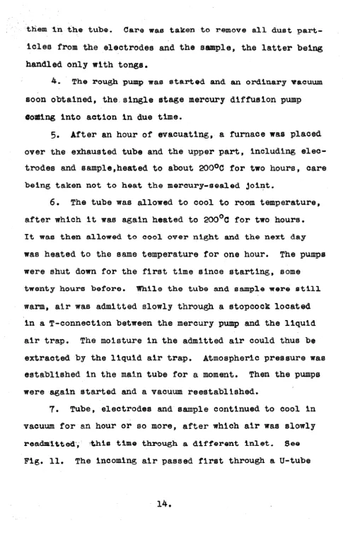
tliem in the tube. Care wa.s taken to remove all dust part-icles from the electrodes and the sample, the latter being handled only with tongs.
4. The rough pump was started and an ordinary vacuum soon obtained, the single stage mercury diffusion pump Goaling into action in due time.
5.
After an hour of evacuating, a furnace was placed over the exhausted tube and the upper part, including elec-trodes and sample,heated to about 200°c for two hours, care being taken not to heat the mercury-sealed joi~t.6. The tube was allowed to cool to room temperature, after which it was again heated to 200°c for two hours. It was then allowed to cool over night and the next day was heated to the same temperature for one hour. The pumps were shut down for the first time since starting, some
twenty hours before. While the tube and sample were still warm, air was admitted slowly through a stopcock located
in a T-connection between the mercury pump and the liquid air trap. The moisture in the admitted air could thus be extracted by the liquid air trap. Atmospheric pressure was established 1n the main tube for a moment. Then the pumps were again started and a vacuum reestablished.
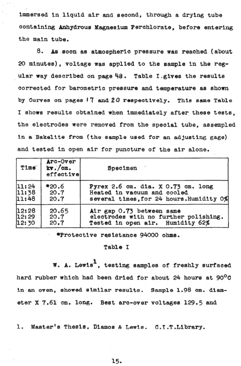
[image:16.615.49.535.23.791.2]immersed in liquid air and second, through a drying tube containing Anhydrous Magnesium Perchlorate, before entering the main tube.
8. As soon as atmospheric pressure was reached (a.bout
20 minutes), voltage was applied to the sample in the reg-ular way described on page
48.
Table I.gives the results corrected for barometric pressure and temperature as shown by Curves on pages I7
and 2 Q reepeetively. Thie same Table I shows results obtained when immediately after these tests, the electrodes were removed from the special tube, aseempled 1n a Bakelite from (the sample used for an adjusting gage) and tested in open air for puncture of the air alone.Arc-over
Time·· kv./om. Specimen effective
11:24 *20.6 Pyrex 2.6 om. dia. X 0.73 cm. long 11:38 20.7 Heated in vacuum and cooled
11:48 20.7 several times,for 24 hours.Humidity 0% 12:28 20.65 Air gap 0.73 between ea.me
12:29 20.7 electrodes with no further polishing. 12:30 20.7 Tested in open air. Humidity 62%
*Protective r~s1stanoe 94000 ohms. Table I
l
w.
A. Lewis , testing samples of freshly surfaced hard rubber which had been dried for about 24 hours at 90°0in a.n oven, showed similar reeulte. Sample 1.98 cm. diam-eter X 7.61 cm. long. Best arc-over voltages 129.5 and
[image:17.613.52.531.47.775.2]130.2. Air gap alone 130.0. Sample
2.54
cm. diameter X 7,59 cm. long. Best arc-over voltage 124.8. Air gap alone 126.o.It is thus possible, under exceptional conditions, to obtain full disruptive strength of the air even when it is 1n contact with a parallel solid dielectric.
ATMOSPHERIC PRE5SURE
The disruptive strength characteristics of air as affected by pressure have been exhaust1ve1y investigated
by Peek1 and others. In order to determine the correspond-2
ing nature of the arc-over strength, Mr. Wilson and I re-placed the Pyrex sample in the vacuum apparatus, carefully dried it as before and, starting with a pressure of about 1 cm. of mercury, read arc-over voltages for a large number of pressures up to values slightly above 76 cm. The temp-erature during the test varied from 22°c to 23°0, a vari-ation small enough to be neglected. A second test was
performed, thie tlme on a sample of glass 1 cm. long placed between flat electrodes of large diameter (about 14 cm.). In this test, a bell-jar was used as the vacuum vessel,
the vacuum used being that obtainable wit~ the rough pump only and in place of heating to 200°0, a high frequency glow
discharg~ was kept about the sample for two hours.
Obser-vations of arc-over voltage starting at atmospheric pres-sure and decreasing to about 1 cm. of mercury were made.
INFLUENCE OF PRESSURE
Fig. 1:2
In Fig. 12, the circles •how the
values for
.73
om. length of Pyrex, and the crosses show the values for 1.04 cm. length of glass. The straight line is thegenerally accepted law of disruptive strength of a1r. The Y-1ntercept is taken from Townsend1
and the ordinate i'or'h ;;1
from our own data for the air alone, Table L, p.
15.
The abscissa are ttrelative air density", since it was long ago 'shown by Townsend2 that the breakdown strength of a gapbetween two plane electrodes is proportional to the number of gas molecules in the gap. Relative air density us a measure of the relative number of molecules in the gap.
l. J .a.Townsand "Electricity in Gases111915, Oxford.
2. Op. cit.
Referred to standard conditions of 76 cm. pressure and 2500, relative air density is
b'.
3.92 b273+t
Where b. 1s cm. or mercury and t ls degrees
c.
In the experiments just described, t was practically constant.It will be observed that the experimental values in both tests seem to lie on two intersecting straight lines of different slope, the upper slope being smaller. We have no ex?lanation for this.
The pronounced Y-1ntercept
or
the lower endor
our experimental curve reminds one of the curves for sphere gaps obtained by Peek1 • Each of Peek's spheres of different diameter produces a curve of spark voltage against
~
having a Y-intercept which increases when the sphe~e diameterd1m1n1ahes. He put it into his formula as a correction
de-pending on the square root of the sphere radius. Physically,
it may mean that a certain voltage is alwars necessary to
start the process of ionization on a large scaleeven for low pressure. Townsend used X-rays or ultra-v&olet l~ght
in all his work and found that the curve passed nearl1 through the or1g1n, whereas Peek used no ionizing source
whatever other than the Cosmic Ray and radioaotive
stances which are always present. Our tests, like Peak's, have been made without X-rays or other abundant source of
ions.
We shall have something to say about the
deion-izing influenoe o~ the solid bodies 1n a spark gap. See
APPENDIX.
At any rate, it is satisfactory in correcting aro-over voltages.to standard conditions of 76 cm. pres-sure and
25°c.
to use the divisor sl on the voltage ob-tained at some other pressurebi·
That is: a teat value, say 17 kv /cm •• obtained at 70 am. p'.l"'essure can be aorl"eated to 76 cm. pressure by dividing by 0.92. The result is18.5 kv./cm. The curve does not pass through the origin, so calculation over any considerable range of pressure must be handled wi~h caution.
Temperature effect will be discussed in the next section.
TEMPERATURES
The formula forb, relative air density, involves the temperature as well as pressure. It was found conven-ient to use our vacuum apparatus, including the
.73
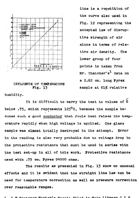
cm. long Pyrex sample, to test the effect of temperature, the pressure remaining constant at 74.2 cm.Fig. 13 illustrates the effect. The upper group of circles is the test of Pyrex (very dry surface). The
[image:21.612.47.507.47.508.2]n
-·
-
AIR. NLV .73< It. /18 o PVR X .73< A
+ PV'R x .62• •\TMI TCHE'I~
~
BARO ~. 7 ...
,16
&~ •,,(
I-
"' ... 111 ..., ... /t •c
I/
i1z
v
'10-·-· ... +
v
.
6
.
I IV
6 I
ij
v
z/
v
=~ '"'"' 2 0 ~A.TUI :ii "'•c
ii ~ ~~g 2 ~(
~ ,.
T 0
"
INFLUENCE OF Tl!:MPERATURE Fig.
13
humidity.
line 1s a repet1\1on of the curve also used in Fig. 12 representing the accepted law of d1srup-t 1 ve strength of air alone in terms of rela-t1ve air density. The lower group of four points is taken from Mr. Thatcher•a1 data on
a 2.62 cm. long Pyrex sample at
61%
relativeIt 1s difficult to carry the test to values of
0
below.75,
which represents123°c,
because the samplebe-·'
comes such a good conductor that Joule heat raises the
temp-erature rapidly when high voltage is applied. One glass sample was almost totally destroyed in the attempt. Error
in the reading is also very probable due to voltage drop in
the protective resistance that must be used in series w1th tne test set-up in all of tnis work. Protective resistance
used with .73 cm. Pyrex 94000 ohms.
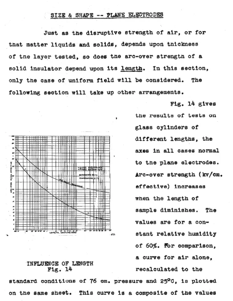
[image:22.614.57.528.40.712.2]SIZE & SHAPE -- PLANE Er,,EOTRODES
Just as the d1srt1pt1ve strength of air, or for tnat matter liquids and solids, depends upon tniekness of tn.e la.ye_r tested, so does tn.e are-over strength of a solid insulator depend upon its length. In this section, only tne case of uniform field will be considered. The following section will take up other arrangements.
~•o 11\
~ H+--l"d-H+l+f't.l-H+--l-++++-H++w+-::~5~~~~~~i~"~'~~: +1--1
~H-f--+-J-','k-f-H+t+J+i-1"-d--++t+t+t+++++-~~~M·='m~•~~~'-++1+~
~ f\I\ 'r--.. 4 TSll'll'~TI RE z, 1 (
INFLUENCE OF LENGTH
Fig. 14
Fig. 14 gives tne results of tests on glass cylinders of
different lengths, the axes in all cases normal to tne plane electrodes. Are-over strength
(k:v/cm.
effeetive) increases when the length of
sample diminishes. The values are for a eon•
stant relative humidity of 60%. For comparison, a curve for air alone, recalculated to the standard oond1t1ona of 76 om. pressure and 25°0, 1a plotted on the same sheet. This curve is a composite of the values round by many different experimenters and com-1led by
[image:23.612.59.537.46.663.2]S~humannl. Tne original was presented for conditions of 76 cm. pressure and 20°c, It has been converted to stand-ard conditions for tne present use. A copy will be found
in Schwaiger'a Elektr1sche Festigkeitslehre, Second Edition 1925 opposite to p. 474.
,
The diameter of the sample was found to have no effect even down to a fibre .02 mm. diameter.· Rice and
Schwaiger each state this general conclusion although nei-ther of them aotvally tested samples much less than l om. diameter.
A glance at Fig. 14 will show that not only does the arc-over strength increase very materially as the
sample is made shorter but an .01 om. glass sample at 60% humidity has more than
twice the arc-over strength of the air gap alone for
1 om. length. Note that this does not mean volt-age. It means volts per centimeter.
Suppose, then,
that a stack of alternate samples of glass, say 1.9
cm. and 2.5 om. diameter,
EFFECT OF
GROOVES respectively, (Fig.15)
(Magnified) Fig. 15
[image:24.615.56.541.40.725.2].
each ·.01 cm. long (thick) be arranged between plane elee-trodes, the enti~e etaak being 1 cm. high. Each large diameter pieoe will aot as a series d1electr1o of high . permittivity. The air spaces between will be stressed
from 5 to 7 times as much as the glass. For rough oalcul-, at1on, suppose the glass acts as a conductor and puts the whole voltage upon the thin air films. The total length of air film 1-s
.5
cm. (taking them all in series). Thestress on the air in these annular gaps'between pieces of larger diameter is thus roughly twioe the stress on the air between the main electrodes elsewhere in the main gap. But the curve shows that the thin films of air, even in con-tact with the glass at 60% humidity, are more than twice as strong as the air alone out in the space between the main electrodes.
The thin a1r-f1lms cannot be broken down before the main gap punctures, which is what we want as the char-act,er1st1o of high air-efficiency insulation.
One detail has been overlooked. Will not the edges where the thin air-film broadens out into the larger space produce some high field ef'feots due to sharp points and edges? With metal spacers as assumed in the rough calculation,
yea;
but with glass spacers -- test will show.Te.ate .on stacks with metal spacers, however, are unsatis-factory. Elec ... trode Spac• ing cm •. .102 .142 .183 .233 .304 .90 .90 Thick-ness of Glass
disks
cm.
.02
.02
.02
.
.018 .02
.02 .025
Aro-over Per cent Aro-over for glass
kV/cm.
Relative cylinder of sametot.-effective Humidity al length kv/cm.effec-tive. 90% humidity.
)
23.0 90 15.0
23.7 90 14.3
22.3 90 13.8
21.8 90 13.2
20.5 90 12.6
19.2 90 10.5
17.3 90 10.5
DISKS OF .ALTERNATE DIAMETER Table II
It has been shown, in this section, that length of path 1n the case of flat paral1e1 electrodes and e. eam-ple whose axis is normal to the electrodes is all-important in detennining the surface gradient of arc-over. Diameter of piece has no influence. Shape of surface may be extremely important. Grooves are beneficial if their dimensions are of the order of .01 to .02 cm. width. Larger grooves may be of value where the ridges are rain sheds or dust shields but,
because of the higher stress put upon the air in the groove, are not to be recommended for surfaces whose arc-over grad-ient must approach the puncture strength of ai~.
SH.APE OF ELECTRODES - FARADOID PRINCIPLE
[image:26.617.53.528.64.459.2]a ·large "hat'', approaches that type of arrangement quite closely. at least as regards arc-over stress along its surf'a.ce.
COAXIAL ELECTRODES Fig. 16
For electrodes
or
all other shapes, no matter what the shape of the insulation surface, ~he arc-over gradlent is non-uniform.One arrangement in part1oular is of interest be-cause its results
can
be gen-eralized to some extent. Fig.16 illustrates a pair of coaxial tubular electrodes. The insulation is so disposed that its surface is parallel to the electric field, the effective voltage gradient at any radius x being
( 1)
-ax- -
dv _ V
~~~~~-R-x l.oge
-r
where V is the t~tal effective voltage between electrodes. It is evident that the effective gradient is greatest at
the surrace or the smaller electrode. Puttlng r ror x in formula (1)
( 2)
[image:27.612.68.518.69.623.2]former case is non-uniform, it seems logical to take its greatest value and determine the length of path over which
V in a uniform fi9ld would produce the same gradient. That ficticious length has been designated "equivalent length" L'.
L' • - -....
~---,..-
r log9~
r
loge~
rt R-r 1s some t1xed va1ue, 1t oan be shown that L' approaches R-r as these radii become very large. Fig. 17, taken from Schwa1ger1, contains both puncture
..
!O 20 10 8 6 If-3 2-
i--~ I-'"·--i---
--'---
--
,_----
....--
-
... ....-
-...~1---
...I
-
~ j--.
i-r- AIRO• LY;c ~x ~L
-- Al<I! Of LY;! L.o\ 'IE
iO iof6o% f4UM. Cl '-XI AL
1-60,r. HUM jP Al IES
2 3 If. 5 6 1 8910 20 30 '10
EQUlVALl!i.NT LE'N(iTH L' Ct'll.
NON-UNIFORM HELD (Sohwaiger) Fig. 17
strength of air and arc-over strength of porce~
lain as they are influ-inced by L'. The data is for a constant rel-ative humidity of 60%. Obviously, only one value of R-r can be expressed by a single curve. The value chosen is 25 om. which is large enough to r,it a good many practical insulators. The dashed curves show corresponding puncture and arc-over strengths in homo-genious fields.
[image:28.612.53.533.42.587.2]It is not surprising that such an increase in are-over strength occurs, in view of the sphere gap tests of Peekl and his results tor parallel cylinders. In those tests, the air films close to curved electrodes exhibit much greater puncture strength (kv/cm) than the air farther away from the electrodes. An explanation for this will be round in the APPENDIX.
These qurves have been reproduced here because
of the1~ relation to the Faradoid principle, which, as
pre-viously described, requires that all exposed (not 1n contact with the electrodes) insulation surfaces be coincident with
either the flux lines or the quipotential surfaces of the electric field. To be strictly unambiguous, the Faradoid principle must require smooth contours, for any groove or ridge whatever introduces dielectrics of different permit-tivity in series. If the walls of the groove follow an equipotential surf ace and the neighboring groove is very close, 1.e. flange between two grooves, is of negligible thickness, the requirements are satisfied. Practical con-struction, however, requires flanges of considerable thick-ness and their extremities cannot merge into the other dielectric medium without disturbance of the ideal flux distribution. Therefore, only smooth contours can, in prac-tlce, be Farado1dal.
At least one insulator constructed upon this principle (Fig. 4) has been shown to be inferior to a
near-1. Op. cit.
ly similar one constructed (Fig. 5) in a non-Faradoidal manner. O'f course, most non-Faradoid insulators will be
far less successful than the authorized versia.:r.:i..
(
The question ls, how can one design the best shape of insulator to flt a given pair of electrodes, or even so modify the electrodes as to secure the very best air-efficiency possible ln the space available?
It see~s unwise to attempt to include in this
report a working method for the design of insulators. Per-haps a few suggestions based upon the forgoing obeerva~iona
will be of value.
l. As a first approximation, the Faradoid form is unquestionably the best.
2. For ordinary humidity conditions, it may be assumed that the arc-over strength of a surface parallel to a uniform f'1el.d is 2/5 the disruptive strength of air :for
-the same length of Rath, Fig.14.
A surface parallel to a non-uniform field will have a somewhat greater a.re-over strength. the value of which can be estimated by reference to Fig. 17. Equiva-lent length of path L' has been given as
L' = r loge .
..1L
rthe electrode in question. Reference to the curve will
give an idea of the 1n~reased arc-over strength.
3.
In a clean location, free from rain, fog, dust of vapors other than pure water, grooves will be practically valueless unless their dimensions are of the order of .01l
to .02 cm. The length of path is not increased by the flanges because just outside their edges, the path is much the same as before.
Inside
the
grooves, the arc-over stress must be greater than for no grooves because part of the other-wise useful length of surface ls occupied by flanges whose permittivity is greater than that of air and the voltage drop consequently less, Fig. 1. Experiment shows that flanges are either detrimental or have no effect whatever in the case of clean insulators subjected to ordinary humidity conditions.4.
In the ease of insulators partly covered bywater drops, dust, salt crystals, etc., flanges act as rain
sheds, dust shields and increased length of path. A clean portion of the surface is usually sheltered from
contamina-tion so that 1ts a.re-over strength is ma:lntA.ined2. while the
dirty portion of the surface aots as a series resistance and
not a dielectric. It is&well known fact that puncture
1. Bee page Z2 •
2. It may be well to, at this time, mention the H. B. Smith
round rod type of insulator for high voltage lines (AIEE
43 p.1263,1924). It consists of a long wood rod capped by
me~al p1a~ee ~o provide unlform field. ~erhapa its lack
voltage of solid dielectrics is very greatly increased by inserting resistance materials in series with the dielectric.
A similar effect seems to have an influence in the case of
1neula~or arc-over.
Schwa1ger1 found that large commercial pin-type insulators had increasing arc-over voltages as the relative humidity of the surrounding air increased from
30%
to95%,
falling off sharply in the rain tests but not falling below the value corresponding to 30% humidity. He further found that medium size insulators of the same type behaved in a similar manner but showed a less exaggerated effect. Small pin-type insulators arced over at voltages independent of humidity up to the rain test 1n which the arc-over voltage fell off considerably. Littleton and Shaver2 have observed that a Pyrex rod around which were twisted two pieces of No. 6 copper wire about 14 inches apart, for electrodes, arced over at voltages increasing with absolute humidity. It is pointed out in explanation, that in all of the above cited
cases, at least one electrode was a piece of small diam~ter
(perhaps ~ or 3
mm.)
wire. The effect of the increase in humidity was probably to increase the equivalent size and curvature of the electrode as well as furnish a series resis-tance in place of a dielectric between the electrode and the1. Elelttrieche Fest1gkeitslehre, 2nd Ed.,p. 424, Fig.421. 2. J.T.Littleton,Jr.& W.W.Shaver of "The Effect of
remaining portions of the insulator. Anything which will tend to relieve arc-over gradient in the p1Aoea where i t is most severe is almost sure to increase the total arc-over voltage.
5.
It may be inferred from the foregoing that modi-fications of the Faradoid form can be made to advantage.Such is the case as has been seen.
There
ts
nothing miraculous about the Faradoid principle. It seems to have been first applied to themath-ematical system of two confocal hyperbolic cylinders as elec-trodes producing confocal ellipses as flux lines. Such a system was many39ars ago analyzed by Maxwe111 • The elec-trodes are ordinarily of large radius of curvature and prob-ably no better contour of the insulation can be found thall that following the flux lines. Other shapes of electrode may, however, not comply w1th the requirement of large ra-d1us of curvature. Such is the difficulty with the rod-and-ring bushing illustrated in Figs.
4
and5.
Both the rod and the ring have small radii of curvature (1 om.). Employing a Faradoid shape of insulation in the way in which it has been done, places a severe arc-over gradient upon the air immedi-ately in contact with each electrode. In spite of a some-what higher arc-over strength observed when insulation isused 1n such a way, the gradient at the electrodes far exceeds the arc-over strength even before the larger part of the
1. Op. c1 t.
insulator surface is near arc-over. The remedy is to remove some of the tnsulattng material, as was done. See F1g. 5. Flux refraction now redistributes the gradient so that its value at.the electrode surface is reduced, and an increase occurs in a location much under-stressed originally. Fig.18 ls not an exae-t, plot but serves to illustrate the contrast
FLUX REFRACTION Fig. 18
brought about by the modification
in shape.
In
order to determine just how far to go in making such a change in contour, elec-trio flux maps must be plotted. The mathematical theory applies to only a few special cases.Suggestions for flux mapping in the case of a three dimensional region having symmetry about one axis of rotation will be found in Moore1 • Additional complication arises due to flux refraction but the
ratio of angle of approach to angle of refractlon 1s easily
computed and a table for every 5 degrees, say, can be made out and used to advantage. The equipotential lines must intersect the flux lines orthogonally, hence they, too, will suffer refraction.but in the inverse direction,bending toward
the no:rmal.
The best insulator contour, then, for a gtven
set"Vioe oan be approaohed by a very difficult and tedious,
· to>be ;sure, method of mapping, in which such factors as
con-/IA q
ductio:n surface due to rain, abnormal arc-over strength due to curvature of electrode and modified gradients due to flux refraet1on are taken 1nto account. In this oonnect1on, it must be emphac1sed that flux refraction in a dielectric cir-cuit does not
alwars
increase the stress on the air.It
does, however, always make the solution of the problem morecompli-cated.
CONTAMINATION OF A SURFACE
Perhaps the most striking effect of the kind en-countered in this investigation occurred in the vacuum vessel in which a Pyrex sample
was
being prepared for the arc-over test at zero humidity. A temperature of about 4-00°0 was maintained for more than an hour simultaneously with the vacuum. The copper electrodes shed their oxide aoating dueto .the elevated temperature, some of the oxide being depos-ited upon the walls of the enclosing tube a.nd some upon the sample. When the test was made, an arc-over voltage of lees than
80%
of the anticipated value was found. The quantity of foreign substance involved was such as to be scarcely observ• able. showing up aea
very slight darkening of the ordinarily bright surface.1'~duces the arc-over strength by uncertain amounts up to, in my observations abo~t 60%. Large volumes of fresh air in
constant circulation seem to be the best remedy. Experiments carried on un~er a bell-jar were impossible when other than zero humidity conditions existed, unless the apparatus was to be completely dismantled and reassembled for each reading.
Oil vapor from an air pump used to bring air from outside the building into the test room caused very definite falling off of arc-over voltage after 40 or more hours.
Several experimenters have stated that such con-tamination as sputtered films of metal, dirt and the like invariably reduced arc-over voltage in a homogenious field. Forteacuel, on the other hand, states that his rod-and-ring bushing (Fig.
4)
had a constant arc-over voltage whetherclean or coated with a three months' accretion of Pittsburgh atmoephere. In the latter case, surface eouQ.:t:l.ot1on' .. rel1nid ·
some of the very high surface gradient at the electrodes just as the increased humidity does in the case of Littleton and Shaver's Pyrex rod.
thoroughly with a paper towel yields are-over voltages in a uniform field corresponding to low (10%-25%) relative
humid-ity, regardless of the humidity of the atmosphere in which the test is made. The soap contains one or more vegetable oils which remain on the glass even after brisk rubbing. The film of oil is, in this case, so delicate that
.2a!
spark ls sufflc1ent to destroy 1t even though the sparkpasses several mm. away from the sample and endures for only a second. Such a coating of oil has been observed to resist the effeot of 65 per cent relative humidity of the atmos-phere for 24 hours and still yield an arc-over test close to the strength of air alone.
JOINTS
The influence of very thin films of air-or other substance of lower permittivity than the sample under test--between electrodes and sample, is an uncertain quantity. All of the tests herein reported, excepting those credited to other experimenters, have been made on samples which had their ends ground off quite flat, no chamfer being made to remove the sharp edge where longitudinal surface and end meet. The electrodes have been turned flat in the lathe and ground or polished down to quite accurate planes. For
exam.pie, the 20 inch diameter (51 cm.) aluminum electrodes
used in testing the longer samples (2.46 cm. and longer) were turned and polished to better than .002 om. maximum deviation from perfect planes. Thus, a very good flt has
b~en ~ecured between electrode and sample. The upper elec-trode rested freely upon the sample, no surrounding frame
being used to guide it. In the teats of the very thin samples (microscope cover glasses) the electrodes and sample were
placed in a Bakelite frame so as to permit a force to be ex-erted upon the$--an attempt to secure good joints. In the
zero hwnldlty tests, both electrodes were guided by suitable
parts of the glass vessel but the guiding was loose enough so as to permit them to make full contact with the sample, a
Tungsten spring forcing them against the latter with a force
of roughly 300 grams. Table III shows to some extent the in-fluence of joints.
Per cent Lengt.h Arc-Over Volt.a~e. effective
Relative of Ends Ends Cha.mf ered Humidity Sample flat ( Thatoherl)
60 9.3 em. 95 kv. 88 Jnr.
60
7.2
76--60 5.0 55
52
60 2.46 31 26
Table III. EFFECT OF JOIN!TS - PYREX
R1ee2 adopted a scheme in which he depressed the electrodes so as to obtain electrostatic shielding of the
1. J.
w.
Thatcher,Maeter's Thesis. The cha.mpher was about1 to
it
mw. and the sample was in contact with theeleo-trode at only a few points. Perhaps .01 to .05 mm. air gap could be assumed.
[image:38.612.58.549.45.558.2]joints between his glass tubes and electrodes, Fig. 19. This has the objectionable feature of giving increased length of pathto the test piece and invariably increasing the arc-over voltage. one cannot be sure whether the
1n-SHIELDED ENDS
Fig. 19 (Rice)
creased voltage is due to long-er sample or bettlong-er Joint. The relation is not merely one of accounting for the additional length of path. The electric f leld symme~ry ls disturbed.
It is felt that the problem of Joints was not com-pletely solved in this 1nveat1-gation but short of producin~ optical flats on both sample and electrode and eliminating absolutely every fleck of dust from the joint, no better so1ut1on was found. Waxes
creep up along the useful insulating surface due to the heat of the arc. Mercury will squeeze out, forming a new part of the electrode having small radius of curvature.
Any manner of fitting the sample into a depression in the electrode effectively lengthens it.
DIELECTRIC CONSTANT.
The permittivity (dielectric constant) of the solid insulation may exert a small influence on its arc-over voltage in air. Table IV illustrates the results obtained on samples of different substances which are
f,
Rel.
Hum.
60
80
90
Kv/cm.effective,Arc-over Voltage--Length 1.02 cm. Bond Bond Quartz Pyrex Cello- Waxed
paper paper Fibre Fibre phane Paper Strip Sta.ck .Ol em .001 Strip Strip
.01
x
2.5
x
om. .0025 ' .004x
1.0 cm. 2.5 cm 1.0 cm. 1.0 cm
21.0 20.7 20.5 15.5 12.0 18.4
20.2 19.2 20.0
--- ---
18.518.0 19.2 19.8
---
---
10.8INSULATORS OF DIFFERENT DIELECTRIC CONST.A.NT
Table IV
Mica Strip
.02
x
1.0 cm.
12.6
10.8 10.0
mally of emall dimensions. Figs. 20 and 21 show the test equipment which was employed in all of the above determ1n-at ions.
ASSEMBLY
[image:40.612.58.519.53.254.2]It is impossible to decide, from the limited data, whether the increased aro-over strength or the paper ana quartz fibre is due to low permittivity or some surface characteristic. The paper was a "Bond" variety O.l mm. thick and the strip 1 cm. wide. The ataok was of 2.5 cm. squares of the same paper not very tightly pressed together (approximately 100 grammes). The quartz fibre was O.l mm.
thick, untreated after manufacture in an oxy-gas flame about
two days before installing in the test gap. The results 1n Table IV for paper and quartz represent many arc-overs of the gap during three days at 90% relative humidity, for each sample.
The paper absorbed moisture rreely. Although 1t was installed with a slight tension, a bow soon appeared in
the strip and, when exposed to 90% relative humidity, the length seemed to have increased 20 per cent.
ABSORBENT QUALITY
Table IV, in the foregoing section may throw some light upon this phase of the probiem. There seems to be no relation between the absorbent quality of the material and its change of arc-over str~ngth with relative humidity of the atmosphere.
Glass is known to decompose on the surface when exposed to moist air. Silica-gel is formed. It is extreme-ly porous, the pores being for the most part
sub-micro-scopic. It is now a well known drying agent and absorber of vapors and gases.
Paraffin and lac (the raw material from which shellac is made) have moisture resisting surfaces.
Paraffin, lac, porcelain, Pyrex and glass (see Figs. 6, 7, 8, 91 10) all show strikingly similar response
to the humidity of the surrounding air.
Paper, the most absorbent of all, seems to suffer very little in arc-over strength, quite in contrast to glass, paraffin, etc.
Cellophane, moisture resisting substance, has a very low arc-over strength even in an atmosphere of only
50%
relative humidity.SURFACE RESISTANCE
In an attempt to get somewhat more conc1ue1ve information on the influence of surface resistance than any thus far discovered in the literature, a rather elabor-ate system of shleldlng, 1nterlock1ng switches and small current measuring apparatus was set up. Fig. 22 shows in diagramatic form, the essential parts exclusive of the high
volt~• traneform.6r from which aro-over voltage was obtained.
It was desired to measure surface resistance and arc-over voltage (without changing the location of the sample and consequently 1ts contact with the electrodes). The
procedure was as follows:
R'ESISTANCE MEASURING EQUIPMENT Fig. 22
grounded, '000 Volts D.C.
was
applied to the upperelectrode by me~ns of tha
single pole, double throw, high voltage switch. An interlock H caused the eleetrometer with its calibrated shunt to be (at the same time) con-nected to the lower
eleo-trade's grounding o1rou1t,
switch G, only, remain-ing closed to maintain the "ground". After a second or so during which time the system "charged up" to steady conditions, a
small trip catch t was released. opening thA grounding
switch G. The electrometer, then in series with the lower plate, indicated the leakage current due to the sample under test.
The next operation was to.throw the high voltage switch over to the transformer position, simultaneously, of course, due to the interlock, switching the electrometer out of circuit, "shorting" it and putting a. ground on the lower elec~rode or the test specimen.
By means of a pulley arrangement, the two halves
A and B of the shield covering the lower electrode were removed
to,'a s·a.re distance and the sample was then ready to have high voltage applied from the transformer. Arc-over vol-tage was read.
If the procedure were reversed and arc-over taken first, a polarization of uncertain magnitude and direction seemed to be present and spoiled the resistance measurement. After ten minutes, 1t disappeared and readings were easily obtained.
Fig. 23 is a combined plot of surface resistance,
upper curve, and arc-over k.v/cm. effective, lower curve, ae
i 1&.l----+----+----<--+---+---l•~+----l--+
l w ,,
5 l•W---+---+~+---+---+----1
"' U, l:;12 i ~1011---1---+---+-+--"...+- X: 10?.~ ::. i ~ 6 1---1----+----<--+- ·----1----j 10&~ I
i >
0
' ~ 6 < 1 1 1
-"'
~
ijl----1-~
0 20 1/0 60 80
l"ER CENT RELATIVE HUMIDITY
SURFACE RESISTANCE
& ARC-OVER STRENGTHFig. 23
100
influenced by relative humidity. No apparent relation exists
be-tween them. A more striking illustration than the curve is a group of individual readings, Table
v.
The data usually presented in
Justification of the statement that no re-lation exists between surface res1etanoe or a solld 1neulator and 1te arc-over voltage 1n air oons1sta of the two sets, (1) Curtis' surface resistance data1 for paraffin which shows the surface
[image:44.612.49.524.46.700.2]Time 11:06 11:16 11:29 11:37 11:45 11:56 12:09 12:24 12:37 12•52 1:02 1:13 1:21 ls3l lt46 2:01
Per cent Surf ace Relative Resistance Humidity Ohms
·54
13.5x
101256
9.657 4.8
60 4.4
61 3,4
62 2.0
63 1.55
65 1.48
67 1.55
69 1.4
70
1.3
70 1.3
71 .84
68 .9
65 1.3
63 1.2
A SAMPLE OF DATA Table V
Arc-Over kv/cm. effective 9.0 8.6 8.75 8.05 8.l 8.75 9.45 9.35 9.2 9.87 10.5 9.85 9.35
8.5
7.9 9.4tivity to be almost independent of relative humidity of the surrounding atmosphere, and ( 2) an arc-over curve for p&r;w--affin, Fib. 10, 12a. Inspection of Curtis' curves, however, shows the points to be erratic, probably due to accidental coming together in puddles, of the minute droplets of mois-ture ordinarily kept separate by the greasy namois-ture of the paraffin surface. One might expect a still greater lining-up of the droplets under the influence of the high field in
the arc-over test. Iu other words, the surface res1et1v1ty
as being absorbed in the silica-gel.
R. J. C. Woodl has presented some interesting arc-over data on large commercial insulators--suspension units and post-type, all porcelain--in which the surface became almost entirely coated with crystalized salt from a natural sea water spray. On clear days, the insulators were dry, but they became moistened by fog on frequent occasions. Voltage close to arc-over was maintained day and night, a l ampere fuse in series with the insulator acting as ap. indicator of occurrence of are-over. It can, as an approx1mat1on, be assumed that the surrace res1et1v-ity per square inch or square cm. is uniform over the entire insulator surface, so completely does the salt coating cover it. A value of total surface resistance was calculated by Mr. Wood for each of the insulators tested (assuming
uni-form surface resistivity) and the arc-over voltage found to be quite consistently proportional to that resistance.
Pyrex cylinders teated in uniform fields in the present investigation, when coated with a generous deposit of salt by spraying sea water upon them, after which they were dried and again moistened with a spray of fresh water while volt-age was applied, yielded .an arc-over voltvolt-age close to that predicted on the basis of Mr. Wood's "Surface 1eakage re-s 1ata.nce11
Time
10:05 10:10 10tl5 10:16
10:17
10:20 10:22 10ti7
5.03 5.08
Surf ace Arc-over "Surface Expected k.v.
Condition k.v.effec- Leakage effective of tive Resistance" Arc-Over
Lgth.+ Cir. (R.J.O.Wood)
Salt coat- 10.3
---
---1ng, Dry 12.5
Salt coat- 5.8 .35 5.0 to 5.2 ing, Moist 5.0
4.2 Salt coat-
7.5
ing,Sprayed 8.3
---
---with .fresh 7.5
water
Cleaned by 30.0
---
---Spray; Dry 29.2
BEHAVIOR OF 4.6 OM. DIAM. X 5.1 CM. LONG P"YREX
CYLINDER. PROTECTIVE RESISTANCE 18500 OHMS.
Table VI
It is not true thatunder ordinary humidity con-ditions, insulation ha.a an arc-over strength proportional to surface resistivity or universally obeying any other law, but in a uniform field, low surface resistivity invari-ably predicts low arc-over strength. In a non-uniform !1eld, however, the effect may be reversed, due to enlarging of the active electrode surface and the substitution of series re-sietance for aeries capacity (see page Z9), up to a certain limit which seems to be the condition of about 90 per cent humidity. Beyond tnat, a reduced surface restivity
in-vs.ria.b1y reduoas are-over strengtn in any kind of' a. field.
ROUGHNFSS
It has been suggested by at least one experimenter that the diminished arc-over etrengtn of an 1neulat1on surface 1n a uniform field as compared witn tne same patn in air alone
is due to sharp points of macroscopic or microscopic d1men• e1ons, water droplets,also, being pictured as tne equ1~alent
of points. That such is not tne case is evidenced by tne lack of dependence of tne arc-over strengtn of Bond paper on rel-ati vj humidity, Table IV. Samples of Pyrex rod, both high-ly poliened, and quite badly pitted, arc-over at so nearly tne same voltage gradient tnat no definite d1st1nct1on can be made between tnem. It
was
noticed on many occasions tnat nicks, scratcnes and otner flaws 1n samples had no influence upon tne patn of tne arc. Only accidentally did tne arc occur close to tne locationor
tne r1aw.The fact of augmented arc-over strength, character-1st1c of surfaces next to sharp points, 1n very narrow grooves
and 11ke situational, eeeme to indicate that at any rate in
homogen1ous fields, no sucn influence of points and scratches snould exist as has been supposed.
Sonwaiger2 finds tnat in tne case of Cart.a and
Durax, tne former a molded paper and the latter a molded
l. The exact details ot tne imformation presumed nere have not been presented but Fige.14 & 16 will illustrate tne prtnciples.
2. ftbersehlagfestigkeit des Porzellans E.T.Z. 26, June 29,
conglomeration, roughening the surface by means of sand
paper made no appreciable difference 1n tne arc-over voltage. Systematic 1rregular1ty such as very narrow grooves w!tn flanges of comparable tnicknese is a source of greater arc-over strengtn, Table II.
IONIZATION
According to tne theory of sparks wn1cn was sug-gested by Townsend1 some initial ionization of the air is
neoissary to start a spark 1n a1r. It was tnougnt that a greater cons1stenoy of readings and pernaps a lower value of arc-over gradient would be found 1f Ultra Violet light were oaueed to fall upon tne sample, tne eleetrodee, or both. A ~uartz-Mercury arc was, accordingly, set up, the light being first directed upon the Pyrex sample, in another test, upon the lower electrode, and finally, upon the entire assembly. The intensity of tne lignt was not measured but the 3 ampere Quartz-Mercury tube was placed only about 75 cm. away from tne sample under test.
At
atmospnertc pressure, the presence of tne Ultra-V1olet 11gnt made no not1ceable change 1n tne arc-overvolt-age or uniformity of readings. The effect was tested over a range of 40% to 70% relattve humidity, results being prao-t1oally tne same as wttnout the Quartz-Mercury tube. More powerful sources of 1onizat1on were not used.
TEST VOLTAGE AND METHOD
In all of tne foregoing work, sine wave voltages, or very closely so, were employed. For samples of lengtn
of .7 cm. and greater, tne hign voltage supply was a 250 kva.,
250 kv •• 50 cycle transformer having one nign voltage term-inal grounded; the voltage controlled by means of a West1ng-nouse Regulating Transformer built for tne purpose. As a
protec~ive resistance in tne nign voltage circuit, ten Zi~oon
resistance rods totalling 187500 on.ms were employed, unless otnerw1se noted. A calibrated voltmeter winding in the main transformer was used to determine tne voltage.
For samples of snorter lengtn than
.7
om., a 1 kva. 6.b kv. 50 cycle transformer wae used and a protectiveresis-tance a.f 35000 on.ms. There were four 110 volt. pr1mar1es.
A motor-driven 1nduct1on regulator was employed for voltage adJustment of tn1s transformer. Aro-over voltages were read tnrough the agency of an instrument potential trans-former rated 5000/2500/125 vol.ts and a 10, 30, 75 or 150
scale a.a. voltmeter whichever was most convenient.
Speed of voltage rise 1n tne use of tne 250 kv. transformer was about 5 to 5.5 k:v. per second. It was
brougnt up to arc-over without intermediate. stops in tne
case of samples of
5
cm. lengtn and greater, 1.e. voltage application to tne sample was at the rate of about 10% of arc-over voltage per second.1nter-mediate stopping was necessary because the rate of travel of the regulator was fixed within rather narrow lim1ts and was too fast for good work. About 5 to 10 seconds usually
sufficed to arrive at arc-over value.
The occurrence of the arc for the longer samples we.s observed by the use of' e. t.e1ephone hea.d set inductively coupled to the ground wire. This gave the observer oppor-tunity to devote ·all his attention to the voltmeter. For the shorter samples. either a mirror was so located that both arc and meter needle could be observed at the same glance or the observer watched the sample with one eye and the meter with the other! Frequently, two observers worked to good advantage. Lastly, on the teats of very short sam-ples, current enough was drawn by the arc to appreciable
"d1p11 the voltage. The observer could then work as
conven-iently as when using the phones. Noise from the transformer and regulator made most audtble observations of either the arc itself or tts duplicate in the phones, difficult 1n the case of lower voltages.
hwnidity. Two different methods of measurement were used. For the larger samples and higher humidities, there were fixed wet a.nd dry bulb 'thermometers in the air stream from a
10° electric fan. For work under the bell-jar and for the low-er humidities, a "preeisiontt hair hygrometer of laboratory type proved ~u1te satisfactory. In the case of zero humid-ity, liquid air and Anhydrone were relied on to extract
mois-ture to a degree negligible, at leae~ for the preaent purpose.
SUMMARY AND CONCLUSIONS
With regard to air-efficiency (the efficiency of utilization of air a