A Flexible Soft DiffServ Test-Bed
1Zyad Dwekat
Kesava Narasimhan
North Carolina State University Beam Reach Networks
[email protected] [email protected]
Yannis Viniotis
Mladen Vouk
North Carolina State University North Carolina State University
[email protected] [email protected]
Abstract. We have constructed a teaching and research SLA test-bed using specially developed soft DiffServ routing nodes operating in a Linux environment. The test-bed, and the associated tools, is intended for various levels of study of SLA translation and mapping algorithms. It is instrumented to provide considerable insight into the DiffServ behavior. The software is more modular, flexible and easier to configure than the “standard” Linux DiffServ offering. This paper presents the architecture of our system, and reports on proof-of-concept experiments that show that it can be used to implement a general Services Level Agreement (SLA) solution and study related issues. Initial empirical studies involves implementation of some of the quality of service (QoS) related IETF drafts and RFCs in a five-node test-bed, including an implementation and empirical evaluation of Expedite Forwarding (EF) PHB, Assured Forwarding (AF) PHB, Virtual Wire (VW) PDB, and of Assured Forwarding PDB.
1. Introduction
Motivation for the work presented here stems from two current trends. One is an
increasing inclination towards voice over IP (VoIP) solutions, both within organizations,
and on a broader scale. For example, NC State University has been conducting a
campus-wide building-scale (50+ VoIP telephones) pilot tests with H323-based VoIP solutions.
H323 and VoIP offer a number of opportunities, both in service expansion (such as
video-phone services), more rapid deployment of services and service change requests,
and cost savings. Although individual VoIP services do not generally require a lot of
bandwidth, what they do require needs to be guaranteed. So far the results of the NC
State tests have been very encouraging. However, some of the issues remain open. This
includes the ability of the typical data networks to actually provide some guarantees for
VoIP and video services, and the availability of such a network.
1
Another trend is towards introduction of some form of quality of service into the next
generation network on the NC State Campus, in the Research Triangle Park metropolitan
area, and in the North Carolina as a whole. Some of the service level agreements (SLA)
that arise in that context involve the desire of the University of North Carolina campuses
to a) have a certain level of guaranteed bandwidth, and b) an ability to share unused
excess bandwidth in a reliable fashion.
The current work is concerned with implementation and evaluation of a test-bed, and its
elements, for evaluation of a general Service Level Agreement implementations using
Differentiated Services (DiffServ) [18]. The goal was to assess whether DiffServ a) can
provide sufficient flexibility for studying general SLA implementations, b) can provide
guarantees that may be needed for QoS-sensitive applications such as voice over IP
(VoIP), and c) whether implementation of expedited and assured forwarding services is
viable and sustainable in this context.
The IETF DiffServ Working Group (DiffServ WG, http://www.ietf.org) has defined the
general architecture for differentiated services, and, as part of that, has focused on the
forwarding path behavior required in routers, known as "per-hop forwarding behaviors"
(or PHBs). Expedited Forwarding (EF) PHB is intended to provide a building block for
low delay and low loss services by ensuring that the EF aggregate is served at a certain
configured rate. Assured Forwarding (AF) PHB [6] allows a service with less guarantees
for forwarding IP packets received from a customer DiffServ domain. Best Effort (BE),
as the name implies, does not offer any guarantees. In a multi-hop/node domain, PHB’s
are combined to offer a desired per-domain behavior. Also several Per Domain Behaviors
(PDBs) have been proposed. One example is Virtual Wire (VW) PDB [9]. VW is
intended to provide "circuit replacement" solution across a DiffServ network, while the
Assured Rate PDB [10], is intended to carry traffic aggregates that require assurance for
This paper reports on an implementation of a soft (programmable) DiffServ router in
Linux which is more flexible, more extensible, and more functional than the DiffServ
solution than usually ships with Linux. Our DiffServ nodes were used to construct the
DiffServ test-bed mentioned earlier. The solution was developed in cooperation with two
industrial partners, BellSouth and Alcatel, with the intent of conducting SLA
experiments, and studying the related issues, both as part of practical research projects,
and as part of teaching-related projects. The partners are using this implementation to
conduct their own DiffServ experiments, including experiments over Internet2 [12]
[17][18].
In our implementation, we tried to make DiffServ modules (Figure 1) [2][3] very clear
and distinguishable, so that they are easier to configure, extend, and test. To configure
DiffServ parameters, we use a script file that defines parameters for each module. This
script interface is extendable to a graphical interface. The implementation also provides
various real time statistics about the system such as queue length, packets dropped,
packets shaped, etc. Currently our research group is working on adding MPLS
extensions, and policy service extensions to our implementation, and looking on the
issues of Traffic Engineering and Fault Tolerance. Our DiffServ implementation is
compatible with DiffServ Informal Model [13] which led to DiffServ MIB [15] and PIB
[14]. So the basic components of the MIB, such as classifier, scheduler, etc., are
implemented. The policy management extension uses COPS-PR.
The paper is organized as follows. Section 2 provides an overview of the soft DiffServ
router implementation. In section 3, we talk about DiffServ test-bed construction and
verification, and about some experiments carried out using the test-bed. In section 4 we
present brief summary and conclusions.
2. 2. Soft DiffServ implementation in Linux
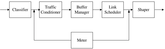
2.1. DiffServ Router Components
buffer manager, shapers and link schedulers.
Classifier Traffic
Conditioner
Buffer Manager
Link
Scheduler Shaper
Meter
Fig. 1. Basic components of a DiffServ Router
A classifier module identifies packets as belonging to certain flows based on certain IP
fields of the packet, and on some rules. A monitoring/metering module serves to collect
various statistics and other useful information about the flows. A traffic conditioner
ensures that the traffic conforms to the negotiated SLA. A buffer manager manages the
queues. It selects the queue for the flows, and it also controls the congestion level in the
queues. A link scheduler module shares the output link among the different flows, or
queues. The link scheduler algorithm should be simple, fast, efficient, fair and scalable.
2.2. Soft DiffServ implementation
The Linux operating system was chosen to implement this DiffServ because it already
has basic support for routing and traffic conditioning which can be leveraged. However,
we found the granularity and functions offered by this basic (“standard”) implementation
insufficient for the studies we wanted to conduct. This prompted us to construct our own
environment on top of it. Linux uses queuing disciplines, classes and filters to implement
traffic conditioning. There is a queuing discipline associated with every network device.
This queuing discipline may further contain more queuing disciplines or classes
embedded within it. All packets enter this queuing discipline and then pass through filters
which then decides where to queue them.
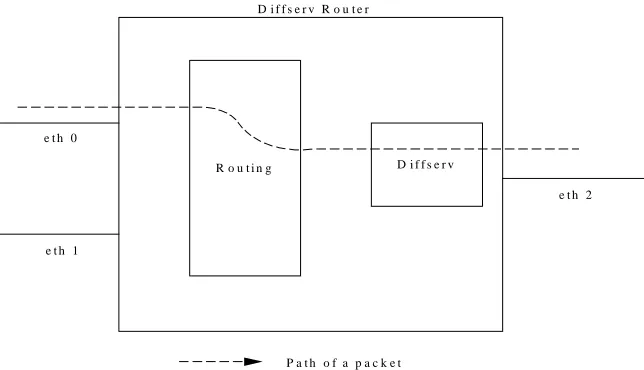
In our system, we have chosen to concentrate on building DiffServ modules rather than
on implementing routing code. Therefore, the DiffServ code acts on a packet only after it
has been routed to the output interface of the Linux box (see Figure 2). In effect, the
input interface of a Linux DiffServ box, it is routed to the output interface based on the
routing table. Then the packet flows through the various DiffServ modules that have been
configured at the output interface, and then is transmitted. With appropriate topology, this
still allows us to investigate practically all issues related to DiffServ-based solutions, but
simplifies isolation and tracking of causes and effects.
R o u t i n g D i f f s e r v
e t h 0
e t h 1
e t h 2
P a t h o f a p a c k e t D i f f s e r v R o u t e r
Fig. 2. Model of our DiffServ system
The entire DiffServ code is created as one kernel module. The existing Linux structures
have been used to some extent in designing this architecture. As mentioned above, Linux
supports queuing disciplines, which enqueue the incoming packets and, depending on the
type of the queuing discipline, processes the packet and then dequeue it. In this
implementation, the DiffServ codes resides in a dummy queuing discipline. The main
functions that we use are enqueue() and dequeue(). When a queuing discipline is created,
it has to be registered with the Linux kernel. At initialization, the various data structures
are initialized to their default values, and the paths for the ARP and other non-classified
(but special) packets are created (see Figure 3). For example, the ARP packets do not
flow through the various DiffServ modules. They are put into a special top-priority
queue. The other queues are handled only if this queue is empty. In addition, this queue is
not affected by the type of link scheduler installed. Regardless of link scheduler type, this
queue is emptied first, and then the other queues are processed according to the link
“control” packets. This is to ensure a smooth flow of control and management packets,
which, if not prioritized, have the potential of stalling the entire system.
Classifier
ARP, Default Packets
ARP queue
Traffic Conditioner
queue 1
queue N
Link Scheduler
Fig. 3. Illustration of the ARP queue
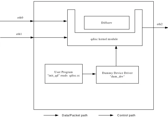
The DiffServ modules are initialized through a user script file called “qdisc.rc”. Since the
DiffServ modules reside in the kernel space, it is not possible for the initialization
init_module() of the DiffServ code to read this script file and initialize itself. So, we have
a program running in the user space called “init_qd”, which reads this script file and
communicates the parameters to the DiffServ modules through a dummy device driver
(Figure 4). This dummy device driver acts as a pipe between the programs running in the
user and the kernel spaces.
D iffserv
D um m y D evice D river "dum _ drv" U ser Program
"init_ qd" reads qdisc.rc
qdisc k ernel m odule eth 0
eth1
eth2
D ata /P ac ket pa th C ontro l path
The user needs to first create the configuration file “qdisc.rc”. In this file, the user
specifies how he/she wants the DiffServ modules to be initialized. It includes specifying
the type of classifier, traffic conditioner, buffer manager, link scheduler, etc. The user
then calls load <device> to load the DiffServ modules at the output interface device. The
DiffServ router is now ready for traffic. The DiffServ modules can be unloaded by
unload device. To re-initialize the DiffServ modules, the user needs to unload it first, edit
the qdisc.rc file and then reload it using load. While running tests, the user can view
operational state and statistics (e.g., average buffer sizes, etc.) of the system by executing
the dump_config.
2.3. Specific DiffServ Components
The services that our test-bed supports are quite rich, and new services are relatively easy
to add. Implemented functions include the following.
• Classification (Behavioral Aggregate Classifier, Multi Field Classifier)
• Traffic Conditioning (Single Rate Three Color Marker, Two Rate Three Color
Marker, Dummy Conditioner - No Conditioning)
• Buffer Management (Normal, Threshold Based,Random Early Detection,
Class-Based Queuing, Microflow Based Queuing)
• Shaper (Rate-Based shaper)
• Metering (Per-Queue statistics): Average queue size, Instantaneous queue size,
Maximum queue size, Per-Flow statistics, Packets Received, Packets Transmitted,
Packets Dropped due to Policing, Packets Dropped by Buffer Manager.
• Link Scheduling (FIFO, Static Priority, Weighted Round Robin [Decrement Mode –
packet Number/Packet Size, Service Mode – Burst/ Non Burst Mode], Self-Clocked
Fair Queuing, Virtual Clock, Hierarchical Scheduler).
2.4. Flow of Control and Data Structures Used
When a packet comes in, it is first directed to the classifier. The classifier goes through
the “Classification Table” and classifies the packet into a certain flow category having
applied to the flow. The traffic conditioner (TC) then takes over the packet and applies
appropriate conditioning rules. For example, if it is a Single Rate Three Color Marker
(SRTCM) traffic conditioner, it refers to the TC-SRTCM table for the SRTCM
parameters, and marks the packet to belong to one of the three colors – Red, Yellow or
Green. The action to be taken is specified by the ACTION table contained in the
TC-SRTCM table. The action includes specifying the outflow id for the packet. Then, the
outflow to queue mapping table is consulted and the queue id of the queue where the
packet should be added is also determined. The buffer manager then queues the packet
according to the rules determined by the type of buffer manager being used. The queue
data table stores the control variables needed for the buffer manager on a per-queue basis.
The packet then remains in the queue until it is dequeued by the link scheduler.
The type of link scheduler used is specified in the link scheduler table. The data (on a
per-queue basis) for the link scheduler is maintained in one of the link scheduler data
tables. The link scheduler then determines which queue is to be serviced based on the
scheduling policies relevant for that link scheduler, and transmits the head packet of the
selected queue.
2.5. Script File
A script is used to initialize the DiffServ module. It is divided into 6 sections –
classification & traffic conditioning section, buffer manager section, que section,
mapping outflows to queues section, link scheduler type section and link scheduler data
section.
Section #1: Classification and Traffic Conditioning
This section basically consists of two portions – classification and traffic conditioning.
The classification can be based on combinations of one or more of the following fields:
•Source Address (with netmask) •Destination Address (with netmask)
•DSCP field (TOS byte) •Protocol
Section #2: Buffer Manager type
This section defines the type of buffer manager to be used and the total queue size (in
bytes). We can define only one type of buffer manager. So this section occurs only once
in the script file. This section also specifies whether shaping is carried out for all the
queues.
♦type : (string). Indicates the Buffer Manager type. It can take the following values •NORMAL : A normal buffer manager.
•THRESHOLD : A threshold based buffer manager.
•RED : Random Early Detect [4] queue management.
•MULTI_RED : RED implemented in a threshold based buffer manager.
Section #3: Define the Queues
The queues are created in this section. Each queue is given a unique number represented
by queue_id. The fields in this section depend on the type of buffer manager selected in
the previous section. For NORMAL queues, we need just the queue id and queue size.
Section #4: Mapping outflows to queues
In this section, the output flows are mapped to the created queues. The output flows are
represented by outflow_id and are the result of traffic conditioning. The queues are
represented by queue_id and have already been created in the previous section. If the
buffer manager is of type THRESHOLD, then we have to qualify the queue_id with a
class_id to indicate which class of the queue is to be mapped. This section occurs once
for each mapping.
Section #5: Define the Link Scheduler type
This section defines the type of link scheduler to be used. The actual data required to
initialize the link scheduler is entered in the next section. This section only specifies the
type of link scheduler and we can define only one type of link scheduler. So this section
occurs only once in the script file.
♦type : (string). Indicates the link scheduler type. It can take the following values •FIFO : A First-In First-Out scheduler.
•PRIORITY : A static priority scheduler.
•WRR : A weighted round robin scheduler.
•VC : A virtual clock scheduler.
•HIERARCHICAL : Hierarchical scheduler
Section #6: Define the Link Scheduler data
In this section, we define the parameters to initialize the link scheduler. The link
scheduler parameters are defined for each queue that will be serviced by the link
scheduler. It goes without saying that these queues should have been defined in section
#3 itself. Different link schedulers have different fields. For example, for PRIORITY
scheduler, we define the priority for each queue. So, the fields for it would be queue_id
and priority for that queue. This section occurs once for each queue that needs to be
serviced
3. DiffServ Implementation Experiments
3.1. DiffServ Test Bed construction
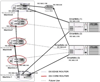
The NC State DiffServ Test-Bed prototype was built using five (5) soft DiffServ Routers
connected to simulate an ingress edge router, a set of core routers, and an egress edge
router, as shown in Figure 5. Of course, more complex topologies are possible. Each
Linux router has three or more separate networking interfaces (e.g., Ethernet adapters).
They are either directly connected to each other, or through switches. The routers are then
configured into a number of subnets, in this example eleven subnets.
Specialized equipment for traffic generation - the SmartBits 200 by Netcom Systems -
was used as single-point measurement units that support packet time stamping in
hardware and providing a precision of around 100 nano-seconds. The interconnection of
routers with the SmartBits was designed to simulate as many traffic sources and sinks as
possible. The basic DiffServ test-bed was extended with SLA supporting scripts and
processes (e.g., EF and AF PHBs and PDBs).
3.2. Experimental Set-Up
The experiments reported here were intended as “proof-of-concept” evaluations that
show that one can support relatively complex PDBs and SLAs. More detailed and
comprehensive experiments are in progress. Alcatel and BellSouth performed their own,
company-specific experiments [12]. In NC State projects, experimental studies are
backed-up with detailed simulations.
A typical experimental scenario might be the following one. There is VoIP traffic
operating in a congested environment. It needs to be protected. Let VoIP traffic be
represented by a 1-3 Mbps flow on a 10 Mbps Ethernet channel (i.e., about 10-30 % of
channel capacity). Assume that typical voice packet size is 128 bytes. Congesting cross
traffic is represented as an almost full load stream (about 9.5 Mbps) of 1514 byte packets.
All routers were configured to have two queues, one for the Expedited Forwarding traffic
and the one for the Best Effort traffic. The Static Priority scheduler was used in one set of
experiments. This was followed by experiments using a version of WFQ called Self
experiments and expand on them. In what follows, where available, the graphs obtained
from NS-2 simulations are shown for comparison next to graphs obtained from empirical
experiments.
3.3. Expedited Forwarding and Virtual Wire Implementation
Virtual wire PDB was used to implement a virtual leased line service over the DiffServ
domain [16]. It was evaluated using real and emulated VoIP streams. The EF PHB used
in the implementation was effected in two ways: a) using Priority Scheduler and b) using
Self Clocked Fair Queuing (SCFQ) scheduler. Both implementations were tested and
measurements were made for loss, delay and jitter.
3.3.1. EF Queue Size Requirements
In this case, Static Priority Scheduler (SPS) was used to give the EF queue priority over
the Best Effort queue. As mentioned earlier, the EF traffic was set to 30% of the 10
Mbps channel capacity, i.e., 3 Mbps, and the EF packet size was 128 bytes (which is
close to a typical voice packet size). To investigate the worse case situation, the Best
Effort traffic IP packet size was set to maximum so that the Ethernet frame size was
always 1514 bytes. Both streams were applied at the ingress router, and they both
followed the same path to the egress router, thus competing for the channel capacity
through the five routers.
EF Buffer size requirement
-20 0 20 40 60 80
0 2000 4000 6000
Buffer size (byte)
L
o
ss R
a
te %
When the EF traffic has absolute priority over BE traffic, the output priority scheduler
typically does not send out any BE packet while there are EF packet waiting. However,
there may be problems even under these circumstances. For example, EF packets
themselves may start a queue build up if an EF packets arrive in an excessive bursts, or
when there is a BE packet already being served. Different sizes of EF and BE packets
may aggravate the situation. Accumulation may get worse with multiple hops, as in the
case of our test bed configuration. Hence, EF buffers need to have an appropriate size to
accommodate the variability and avoid packet loss and undue delays.
To get a rough idea of how much buffer size we need for per-hop EF queue (and to
explore the usefulness of the test-bed for experiments of this type), let us do a simplified
calculation and then compare it with observations in the test-bed. Consider a single
router, and consider the situation where an EF packet arrives just at the moment where a
BE packet is already in the process of being served. Given the previous assumptions
about the parameters and rates (i.e., 10Mbps channel, 3Mbps EF rate of 128 byte
packets, and BE frame size of 1514 bytes at 9.5 Mbps), then, at worst:
Service Time for one BE packet (Tb) = 1514 x 8 bit /10,000,000 bps = 1.2112 msec
Avg. No of EF packets arriving during Tb = Tb x (3,000,000 bps / 128 x 8 bits per packet )
= 1.2112 x 2.9 = 3.5 packets
This gives approximate worst case numbers for one router in the packet path. It assumes
that one BE packet is being serviced at the time a EF packet arrives. Over five router
hops this can accumulate to around (5 x 3.55 ) 18 packets of delay if we assume that the
burst length is the same on all routers, i.e one packet. The problem becomes compounded
when we also consider packet accumulation due to bursts which vary in length between
one packet and a maximum burst of 3.5 (i.e 4) packets. With this assumption, the
average burst length is (4/2) 2 packets. Hence, the packet backlog now becomes (18x2)
36 packets.
An experimental estimate of the parameters was done by gradually increasing the EF
conditions, this occurred at around queue size of 4480 bytes. This is approximately equal
to 35 EF packets which is close to the 36 packets worse case analysis number computed
earlier. Figure 6 above illustrate the results.
3.3.2. Effect of BE packet size on Delay and Jitter of EF traffic
In this experiment, the EF Buffer sizes were set according to the results from the previous
section (i.e., 4480 Bytes) . With this buffer size, the EF traffic was protected against full
load Best Effort traffic. The next step was to see if the delay and the jitter requirement for
the emulated VoIP streams can be met for the worst case background- or cross-traffic.
(Priority scheduler, BE = 8 Mbps, EF(128 bytes) = 1 Mbps, Buffer size = 4480)
Fig.7. Experimental EF delay and jitter vs. background BE packet size(Priority)
First, we varied the background BE packet sizes to see the effect the packet size has on
the delay and the jitter of the EF traffic. The results are shown in Figures 7 (priority
experiment), 8 (priority simulation), 9 (SCFQ experiment). Priority scheduling
simulation shows that the average EF delay increasing linearly with the BE cross-traffic
packet size. This EF delay comes from two sources. The first source is due to events
where a BE packet is in the process of being served when the EF packet arrives (and,
therefore EF packet needs to wait for BE service to finish). The second delay come from
waiting behind other EF packets in a queue. Both delays can be affected by the BE packet
size. The larger the BE packet size, the longer the EF packet has to wait, and during that
time more EF packet may also arrive into the queue and this result in an increased
average EF delay.
EF Avg. Delay & Jitter vs BE packet size(Priority)
0 1000 2000 3000 4000 5000
0 128 256 384 512 640 768 896 1024 1152 1280 1408 1536 1664
BE paket size (Bytes)
Avg Delay (micro
sec)
0 0.1 0.2 0.3 0.4 0.5 0.6 0.7
Jitter (m
s)
Simulations show that the EF jitter also increases with the BE packet size, but this
increase may not be linear. EF jitter comes from the variation in the delay. This variation
depends on many factors. For example, on whether the EF packet arrives into an empty
or non-empty queue, it depends on the queue size (tail-drop), and on whether a BE
packet, or another EF packet, is being served when the EF packet arrives, etc. Most of
these factors also interact with the size of BE packets.
Fig. 8. EF delay and jitter vs. background BE packet size using ns-2 simulation for priority scheduler
(SCFQ scheduler, BE = 8 Mbps EF(128 bytes) = 1 Mbps Buffer size = 4480)
Fig. 9. EF Delay and Jitter vs. BE packet size (SCFQ)
Inspection of the experimental data shows that the measurements agree with the
simulations to a reasonable degree, and the collective performance of the test-bed is
consistent with the expectations. Of course, specific studies do need to take into account
EF Avg. Delay & Jitter vs BE packet size(SCFQ)
0 1000 2000 3000 4000 5000
0 128 256 384 512 640 768 896 1024 1152 1280 1408 1536 1664
BE packet size
Avg. Delay(micro sec) 0 0.1 0.2 0.3 0.4 0.5 0.6 Jitter (ms) Avg delay Jitter
EF Avg Delay & Jitter vs BE packet size (ns-2)Simulation
0 1 2 3 4 5 6 7 8 9
0 128 256 384 512 640 768 896 1024 1152 1280 1408 1536 1664 1792 1920 2048 2176
BE packet size
their specific parameters, as well as possible additional parameters and environmental
settings.
3.3.3. Effect of BE rate on Delay and Jitter of EF traffic:
To illustrate how the BE cross-traffic effects on the EF streams can be studied within the
test-bed, the BE load was varied in steps show in figures below. The average delay and
jitter were measured for the EF traffic. Both Priority scheduler and the SCFQ scheduler
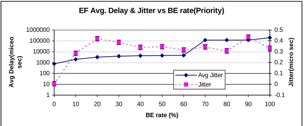
were used. The results are shown in Figures 10 (priority experiment), 11 (priority
simulation), and Figure 12 (SCFQ experiment).
(Priority scheduler, BE(1500 bytes), EF(128 bytes) = 1 Mbps, Buffer size = 4480)
Fig. 10. Experimental EF packets jitter vs. background rate for Priority scheduler
Fig. 11. EF packets jitter vs. background rate for the ns-2 simulator
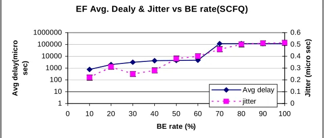
EF Avg. Dealy & Jitter vs BE rate(SCFQ)
1 10 100 1000 10000 100000 1000000
0 10 20 30 40 50 60 70 80 90 100
BE rate (%)
A v g delay( m icro sec) 0 0.1 0.2 0.3 0.4 0.5 0.6 Ji tter (mi c ro sec) Avg delay jitter Avg Delay & Jitter vs B E rate priority
(ns-2)Sim ulation 0 1 2 3 4 5 6 7
0 10 20 30 40 50 60 70 80 90 100 B E rate
Avg . Del ay (m s) 0 0.1 0.2 0.3 0.4 0.5 Ji tter (m s)
Avg D elay
Fig. 12. Experimental EF packets jitter vs. background rate for the SCFQ scheduler
All graphs (real experiments and simulation) show that EF average delay increases with
BE rate. However, in the experiments, when the BE load reaches about 7 Mbps (and EF
flow= 3Mbps), the capacity of the link is exceeded (100% link utilization) and there is a
sudden jump in the delay figures for the EF stream (although there were no losses in the
EF stream). This is probably due to a combination of effects resulting from the BE
over-pressure on the link. For example, full utilization of the link maximizes the probability
that a BE packet is being served when an EF packet arrives, but it also must have some
additional influence, something that the simulation did not capture. In detailed
experimental evaluation this effect would merit further investigation.
3.4. An Assured Rate PDB Implementation
There is a demand for assured forwarding (AF) of IP packets over the Internet. The
Assured Rate PDB is intended to carry traffic aggregates that require assurance for a
specific bandwidth level, but not necessarily of the delay and jitter. In our
proof-of-concept experiments with five serially connected DiffServ capable routers, Assured Rate
PHB was effected using Single Rate Three Color Marker SRTCM for traffic
conditioning, Multiple Threshold RED (Random Early Discard) for Buffer Management,
and Static Priority for scheduling
EF Avg. Delay & Jitter vs BE rate(Priority)
1 10 100 1000 10000 100000 1000000
0 10 20 30 40 50 60 70 80 90 100
BE rate (%)
Avg Delay(m
iceo
sec)
-0.1 0 0.1 0.2 0.3 0.4 0.5
Jitter(m
icro sec)
3.4.1. Assured Rate PDB Specification - Edge Rules
As packets enter the domain from the ingress router they are classified into the four AF
classes, or the default Best Effort class, according the filter rules set in the ingress router.
Each filter is associated with a traffic profile specified by Single Rate Three color Marker
(SRTCM) parameters for each class. All the four classes are set to the same SRTCM
parameters and have committed information rate (cir) of 1,000,000 bps (1 Mbps).
3.4.2. Per Hop Behavior configuration
After marking the packets using Afx1, Afx2,and Afx3 PHBs, each packet must be treated
based on its DSCP value as follows. “red” packets are dropped at ingress router. Within
each AF class, a congested DiffServ node tries to protect packets with lower drop
precedence, the ones with value “green,” from being lost by preferentially discarding
packet with higher drop precedence value, i.e., “yellow.” This was accomplished by the
configuration described in the following text. Note that we use lower case “red” to refer
to the color of the packet according to its traffic profile, and upper case “RED” to refer to
Random Early Discard as a buffer management technique. Four queues were set for the
four AF classes, and a fifth queue for the Best Effort traffic. Priority scheduler was used
to give AF queues more priority over the Best Effort. Multiple RED threshold buffer
manager was used when we set different RED threshold parameter for the “green” and
the “yellow” .
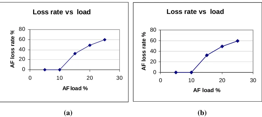
3.4.3. An Empirical Evaluation
We applied four flows at the ingress router representing the four AF classes, and one flow
represent the BE traffic. As mentioned earlier, the AF flows were conditioned to 1 Mbps.
We started by fixing the BE rate at 9 mbps (90% load), and increasing the AF rate
gradually and measuring the loss rate. The results are shown in Figure 13 (a) below. We
see that the AF flows see no losses until they reach their guaranteed rate of 1 Mbps. After
Loss rate vs load
0 20 40 60 80
0 10 20 30
AF load %
AF loss rate
%
Loss rate vs load
0 20 40 60 80
0 10 20 30
AF load %
AF loss r
a
te %
(a) (b)
Fig. 13. AF loss versus AF load. a) BE load = 9 Mbps b) BE load = 1 Mbps
The same experiment was repeated with BE fixed at 1 Mbps (10 % load). Again the AF
rate was gradually increased . As shown in Figure 13 (b) , a behavior similar to the
previous case was observed. This mean that whatever the Best Effort traffic rate is, the
AF traffic will get its guaranteed rate, but when looking at 13 (a) and (b) we noticed that
AF traffic was conditioned and dropped the same way in both situations although there is
plenty of available access bandwidth in the second setting. This is an interesting situation.
It indicates that this particular solution may not be the best one to use if one wants to
make use of excess capacity. Another solution may be a better one, one where the packets
are downgraded to BE. However, that solution may carry with it the reordering problem,
and may require a more sophisticated scheduling.
The set of experiments carried out using the AF traffic is very straight forward, and the
configuration is one of many ways of implementing AF PHB. Implementation has
yielded results consistent with simulations, and it has demonstrated that the SLA-test-bed
is ready to implement fairly complex SLAs involving EF, AF and BE traffic.
4. Conclusions and Future Work
The principal objective of the work presented in this paper was to describe a flexible
implementations, either in-class - as a teaching tool, or for in-depth research. We
implemented two basic PHBs and some interesting PDBs.
Expedited Services Virtual wire PDB was used to implement a virtual leased line service
and to demonstrate ability of the test-bed to support expedited forwarding. EF
implementation was evaluated using real and emulated VoIP streams. The EF PHB was
effected in two ways: a) using Priority Scheduler and b) using Self Clocked Fair Queuing
SCFQ scheduler. Both implementations were tested and measurements were made for
loss, delay and jitter.
Assured Rate Services. Assured Rate PDB of the SLA test-bed was implemented using
AF PHB. The latter was effected using Single Rate Three Color Marker SRTCM for
traffic conditioning, Multiple Threshold RED for Buffer Management, and Static Priority
for scheduling. The guaranteed rate for each AF flows was supported regardless of the
Background Best Effort traffic, while the nonconforming AF packets were dropped.
Experiments were run to ascertain that the AF service was operational, and demonstrate
its possible use.
We have plans to extend our DiffServ implementation to remove its one-interface per
router limitation. Although the latter does not prevent us from studying all topologies of
interest, and, in fact, it allows us to very cleanly separate different effects, it may require
more equipment than is sometimes desirable.. The test-bed is being used to explore issues
related to new and different DiffServ elements, a variety of SLAs and domain-level
solutions, and a number of quality of service algorithms. One interesting area of work is
adaptive queue management (AQM) based on different variants of RED and other
algorithms, effects of MPLS and QoS-enhanced MPLS functionalities, as well as
exploration of new schedulers that would help maximize utilization of per-customer
resources (such as bandwidth) on domain-wide basis, and contribute to successful
end-to-end quality of service implementations and guarantees.
5. References
Quality of Future Intenet Services (QofIS'2000), Lecture Notes in Computer Science (Springer-Verlag) vol. 1922, pp. 167-181.
[2] Bernet, Yoram., Binder, James., Blake, Steven., Carlson, Mark., Carpenter, Brian.,Keshav, Srinivasan., Davies, Elwyn., Ohlman, Borje., Varma, Dinesh., Wang, Zheng., Weiss, Walter., “A framework for Differentiated Services”, Internet Draft, February 1999.
[3] Blake, S., Black, D., Carlson, M., Davies, E., Wang, Z., and Weiss, W., “An
Architecture for Differentiated Services”, RFC 2475, December 1998.
[4] Floyd, S., and Jacobson, V., “Random Early Detection gateways for Congestion
Avoidance”, IEEE/ACM Transactions on Networking, V.1 N.4, August 1993, pp. 397-413.
[5] Golestani, S.. “A self-clocked fair queueing scheme for broadband applications”.
In Proceedings of IEEE INFOCOM'94, Toronto, CA, June 1994.
[6] Heinanen, J., Baker, F., Weiss, W., and Wroclawski, J., "Assured Forwarding
PHB Group", RFC 2597, June 1999.
[7] Heinanen, J., and Guerin, R., "A Single Rate Three Color Marker", RFC 2697,
September 1999.
[8] Narasimhan, Kesava Prasad.,” An Implementation of Differentiated Services In A
Linux Environment.”, A thesis submitted at North Carolina State University of the requirements for the Degree of Master of Science.
[9] V. Jacobson, K. Nichols, and K. Poduri. The "virtual wire" per domain behavior. Internet draft, draft-ietf-DiffServ-pdb-vw-00.txt, work in progress, July 2000. [10] N. Seddihg, B. Nandy, and J. Heinanen. An assured rate per-domain behavior for
differentiated services. Internet draft,draft-seddigh-pdb-ar-00.txt, work in progress, October 2000.
[11] Zyad Dwekat, Amit Kulkarni and Mrugendra Singhai “ Verification Test report for soft DiffServ router implementation “, June 2000.
[12] Aziz Mohammad, Mladen Vouk, Emanuele Jones, Hubert Ogier, "DiffServ Experiments: Analysis of the Premium Service Over the Alcatel - NCSU Internet2 Test-bed", 2nd European Conference on Universal Multiservice Networks ECUMN'2002-Colmar, France.
[13] Bernet, Y., et al. "An Informal Management Model for DiffServ Routers", Internet Draft <draft-ietf-DiffServ-model-06.txt>, February 2001.
[14] Fine, M., et al. " Differentiated Services Quality of Service Policy Information Base", Internet Draft <draft-ietf-DiffServ-pib-03.txt>, March 2001.
[15] F. Baker, K. Chan, A. Smith, "Management Information Base for the Differentiated Services Architecture", draft-ietf-DiffServ-mib-14.txt, October 2001
[16] Jon Bennet..et al, “An Expedited Forwarding PHB”, Internet-Draf, April 2001. [17] M.A. Vouk, L. Bernold, M. Ammar, J. Mackenzie, S. Wright, R. Hutchins, J.
Streck, “Real-Time Tele-Operation of Remote Equipment,” Internet2 Demos in
Atlanta, October, 2000 (http://apps.internet2.edu/html/demos.html,
http://i2dv.nwu.icair.org/videospace/index_10_2000.html )