18th International Conference on Structural Mechanics in Reactor Technology (SMiRT 18) Beijing, China, August 7-12, 2005 SMiRT18-G03-2
A GENERIC VALIDATION METHODOLOGY AND ITS APPLICATION
TO A SET OF MULTI-AXIAL CREEP DAMAGE CONSTITUTIVE
EQUATIONS
Qiang Xu
School of Automotive Engineering, Faculty of Applied Design and Engineering
Swansea Institute of Higher Education, A member of The University of Wales
Swansea, UK,
Phone: UK 01792481168, Fax: UK 01792481168
E-mail: [email protected]
ABSTRACT
A generic validation methodology for a set of multi-axial creep damage constitutive equations is proposed and its use is illustrated with 0.5Cr0.5Mo0.25V ferritic steel which is featured as brittle or intergranular rupture. The objective of this research is to develop a methodology to guide systematically assess the quality of a set of multi-axial creep damage constitutive equations in order to ensure its general applicability. This work adopted a total quality assurance approach and expanded as a Four Stages procedure (Theories and Fundamentals, Parameter Identification, Proportional Load, and Non-proportional load). Its use is illustrated with 0.5Cr0.5Mo0.25V ferritic steel and this material is chosen due to its industry importance, the popular use of KRH type of constitutive equations, and the available qualitative experimental data including damage distribution from notched bar test. The validation exercise clearly revealed the deficiencies existed in the KRH formulation (in terms of mathematics and physics of damage mechanics) and its incapability to predict creep deformation accurately. Consequently, its use should be warned, which is particularly important due to its wide use as indicated in literature. This work contributes to understand the rational for formulation and the quality assurance of a set of constitutive equations in creep damage mechanics as well as in general damage mechanics.
1. INTRODUCTION
Creep damage mechanics, originated by Kachanov in 1958, has been tentatively developed to help to deal with the creep damage problem in engineering design (Kachanov, 1986; Boehler, 1990; Lemaitre and Chaboche, 1990; Lemaitre, 1992; Krajcinovic, 1996; Skrzypek and Ganczarski, 1999; Murakami and Ohno, 2000; Altenbach and Skrzypek, 2000; Lemaitre and Desmorat, 2005; and Betten, 2005). It is evident that significant progress has been made in various aspects including theory (phenomenological approach or unified irreversible thermodynamics formulation, anisotropic damage theory), applications, experimental observation and experimental methodology, and even optimization. More over, the author has, recently, become more interested in and aware of a number of papers in the following aspects: 1) the concept and evolution of damage (Cauvin and Testa, 1999; Krajcinovic and Mastilovic, 1995; Olsson and Ristinmaa, 2003; and Zyczkowski, 2000), 2) non-classical and anisotropic creep deformation and creep damage constitutive equations based on thermodynamics (Lemaitre, Desmorat and Sauzay, 2000; Voyiadjis and Zolochevsky, 1998; Betten, Sklepus and Zolochevsky, 1998; Voyiadjis and Zolochevsky, 2000; and Zolochevsky and Voyiadjis, 2005), 3) continuum creep damage model based on nucleation, growth and coalescence of voids (Michel, 2004; and Gaffard, Besson and Gourgues-Lorenzon, 2004), and 4) multi-axial experimental data including damage distribution (Sakane and Hosokawa, 2000; and Gaffard, Besson and Gourgues-Lorenzon, 2004); the literature is huge and only name a few here. Thus, as the research about constitutive equation development is so diverse and is developing rapidly, it is particularly important to distil the information to assess and, then refine, if necessary, the generic theory and/or methodology to ensure its general applicability.
More specifically, the formulation of a set of creep damage constitutive equations may be based on phenomenon, micro-mechanics, or thermodynamics. Firstly, the phenomenological approach can be broadly classified into weak coupling and strong coupling between damage and deformation. In the case of weak coupling the effect of material damage in elastic properties is disregarded and a coupling is established by introducing the damage variables into the constitutive equation with the concept of effective states variables. Within the weak coupling approach, a set of creep damage constitutive equations for uni-axial tension is generalised for multi-axial applications, which is typified by KRH (Kachanov-Rabotnov-Hayhurst) approach (e.g. Leckie, 1978; Hayhurst, 1972; Hayhurst, et al, 1984; Kowalewski et al, 1984; Perrin and Hayhurst, 1996). Secondly, creep damage constitutive equations have also been formulated based on nucleation, growth, and coalescence of voids (e.g. Michel, 2004; and Gaffard, Besson and Gourgues-Lorenzon, 2004). Thirdly, it has been formulated based on thermodynamics (Lemaitre and Chaboche, 1990, Lemaitre and Desmorat, 2005, Lemaitre, Desmorat and Sauzay, 2000; Voyiadjis and Zolochevsky, 1998; Betten, Sklepus and Zolochevsky, 1998; Voyiadjis and Zolochevsky, 2000; and Zolochevsky and Voyiadjis, 2005). Though the research work is diverse and dynamic, the capability of a set of constitutive equation to depict observed multi-axial material behaviour needs to be ensured. However, the formulation and validation may have not been addressed adequately and quite often validation has either been ignored or been mixed up with calibration. That is the concern of this paper.
0.5Cr0.5Mo0.25V ferritic steel is an important material widely used in UK power generation stations. A set of conventional creep damage constitutive equations has been developed and been used in component design analysis (e.g. Perrin and Hayhurst, 1996; and Hayhurst and Miller, 1997; Hayhurst and Xu, 1997a; Hayhurst and Xu, 1997b; Hayhurst and Xu, 1997c and Hayhurst and Xu, 1997d). However, a critical review revealed its deficiency inherent from its generalisation method, namely: this method used lifetime (under plane stress condition) only and ignored creep deformation consistency requirement (Xu, 2000a and Xu, 2000b). Thus, its general applicability is questionable. In fact, other researchers have reported a discrepancy between the predicted and experimentally observed damage development for a notched bar, though on different material (Kobayashi et al., 1998). Subsequently, a new set of creep damage constitutive equations for this material at 590 °C was proposed in which two functions of states of stress were incorporated to better depict the damage influence on creep deformation and creep rupture (Xu, 2000a and Xu, 2000b). For this set of constitutive equation, preliminary validation and a validation methodology was addressed (Xu, 2001c; and Xu and Barrans, 2004).
2. CREEP DEFORMATION AND CREEP DAMAGE
2.1 The initial concept of damage in uni-axial creep deformation
The term Continuum Damage Mechanics (CDM) was proposed by Jason and Hult (1977), though the basic idea is due to Kachanov (1958). The later introduced a continuous scalar field variable and called it “continuity”:
o net
A A =
ψ (1)
whereAois the initial cross-sectional area andAnetis the real carrying area decreasing as a result of deterioration due to creep. Furthermore, a rate evolution equation forψ valid in uni-axial tension was proposed:
, ν ψ σ ψ ⎟⎟ ⎠ ⎞ ⎜⎜ ⎝ ⎛ =C (2)
where C andνare material constants. The variableψ =1 initially and decreases toψ =0; the later value denotes total rupture or initiation of rupture front (macro-damage).
The damage variable was introduced by Odqvist and Hult (1961) as:
o net o A A A − = − = ψ
ω 1 (3)
Its value is initially zero and increases to 1. The evolution equation was generalized to
( )
σω ~
f
=
(4)
where f is a non-decreasing function, and
ω σ σ − = 1 ~ (5)
The theoretical maximum value of ω, namely =1, is often being replaced by a certain smaller value ωf.
Rabotnov assumed that damage affects also the strain rates and proposed the following constitutive equations of creep and evolutions for damage:
(
1)
,1
m n
C − −
= σ ω ε
(
)
μ ν ω σ ω= − − 1 2 C (6)with six material constants C1, C2, n, m,ν,μ,depending on the temperature.
However, how to generalize this approach for multi-axial state of stress is a tremendous challenge requiring a good understanding of plasticity theory, the definition, quantification, and evolution of damage variables, and the coupling between creep deformation and damage.
2.2 The main characteristics of creep deformation and creep damage
The creep deformation can be typically divided into primary, second, and tertiary stages; while the damage process is often understood (with great simplification) as a process of nucleation, cavity growth and coalescence. The creep rupture may be featured as either ductile or brittle and the macroscopic rupture occurs at the end of tertiary stage deformation. Furthermore, the following observations are made in order to establish a better rational for the formulation for a set of creep damage constitutive equations:
1) The classical creep deformation theories were mainly developed for, and then applicable to, steady state. On the other hand, creep damage developed significantly, probably, mainly in the tertiary stage, and led to rupture in the end.
2) Thus, a set of creep damage constitutive equations should predict the steady state creep deformation by assuming no damage. It is reasonable to attempt to expand and incorporate the conventional creep deformation theories for steady state as the starting point in the developing creep damage constitutive equations. However, we should not be confined unintentionally.
3) Creep rupture equivalent stress (or strength) and creep strain exhaustion are two traditional approaches. They are two separate observations of the same problem and are complementary to each other. So, a set of creep damage constitutive equation should produce results consistent with both. 4) It is conventionally accepted that no volume change during creep deformation. That implies that
need of gradient plasticity theory which is beyond the coverage of this paper and will not discussed further; the latter precisely relates to the formulation.
5) There are non-classic theories such as the Drucker-Prager yield criterion, anisotropic yielding criterion, kinematic, mixed hardening, and overlay hardening rules. They may be potentially needed for advanced creep damage constitutive equations.
6) There are several definitions of damage and their use in damage mechanics in general or in creep damage mechanics specifically. For brevity and due to the limit of the space for this paper, they will not be included and reviewed here. Interested reader can refer to the books by Lemaitre and Desmorat (2005) and Betten (2005) and individual papers directly.
3. TYPICAL CREEP DAMAGE CONSTITUTIVE EQUATIONS
3.1. Phenomenological KRH type creep damage constitutive equations
The phenomenological approach was originated by Kachanov (1958) and it can be broadly classified into weak coupling and strong coupling between damage and deformation. In the case of a week coupling the effect of material damage on an elastic properties is disregarded and a coupling is established by introducing the damage variables into the constitutive equation of the continuum solids when the effective state variables concept is used (Leckie, 1978; Hayhurst, 1972; Hayhurst, et al, 1984; Kowalewski et al, 1984; Perrin and Hayhurst, 1996).
The uni-axial form creep damage constitutive equations for 0.5Cr0.5Mo0.25V ferritic steel at 5900C are written as (Hayhurst and Miller, 1997; Perrin and Hayhurst, 1996):
(
1−)(
1−ω)
) Η) − σ( =ε
φ
1 Asinh( B
(7)
ε ⎟ ⎠ ⎞ ⎜ ⎝ ⎛
Η Η σ =
Η h 1- ∗ (8)
( )
43
= φ
φ Kc 1- (9)
*
ε =
ω C (10)
where A, B, C, h, H* and Kc are material parameters. H represents the strain hardening that occurs during
primary creep; initially H is zero and as strain is accumulated, increases to the value of H*. Φ describes the evolution of the spacing of the carbide precipitates which is known to lead a progressive loss in the creep resistance of particle hardened alloys as ferritic steels. ε*= 23εijεij is the rate of effective creep strain while
ω represents intergranular caviation damage and varies from zero, for the material in virgin state, to ωf = 1/3,
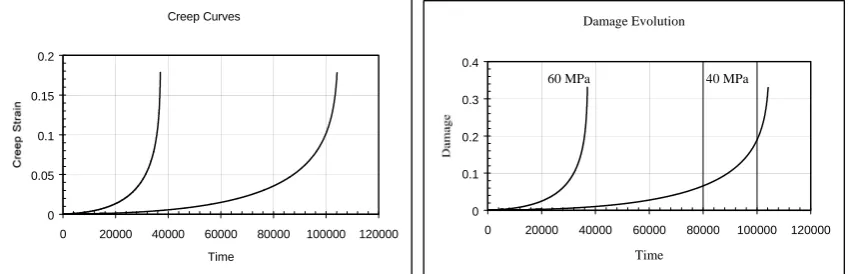
when all the grain boundaries normal to the applied stress have completely caviatated (Perrin and Hayhurst, 1996), at which time the material is considered to have failed. The creep curves and damage evolutions are shown in Fig.1.
Creep Curves
0 0.05 0.1 0.15 0.2
0 20000 40000 60000 80000 100000 120000
Time
Damage Evolution
0 0.1 0.2 0.3 0.4
0 20000 40000 60000 80000 100000 120000
Time
60 MPa 40 MPa
Fig. 1 Creep curves and damage evolution under uni-axial tension for stress of 60 and 40 MPa
(
1−φ)(
1−ω)
) Η) − ( σ σ =ε Asinh( 1
2 e e ij ij B 3S (11) e e - ⎟ε ⎠ ⎞ ⎜ ⎝ ⎛ Η Η σ =
Η h 1 ∗ (12)
( )
43
= φ
φ Kc 1- (13)
υ σ
σ e
e* 1
Cε
=
ω (14)
where <> is heavy step function andνis stress state index defining the multi-axial stress rupture criterion. The
adopted function of states of stress σ1 σe υwas originally proposed by Cane according to Perrin and Hayhurst (1996). The value of 2.8 for and ν is obtained through calibration of isochronous rupture loci in plane stress condition and a couple of multi-axial tests (Perrin and Hayhurst, 1996). A length discussion on its determination can also be found there (Perrin and Hayhurst, 1996). For completeness the material constants for this material at 5900C are given below (Hayhurst and Miller, 1996):
A = 2.1618x10⁻⁹ MPa h-1 B= 0.20524 MPa-1 C=1.8537
h = 2.4326x10⁵ MPa H* = 0.5929 Kc= 9.2273X10⁻⁵MPa-3 h-1
υ = 2.8
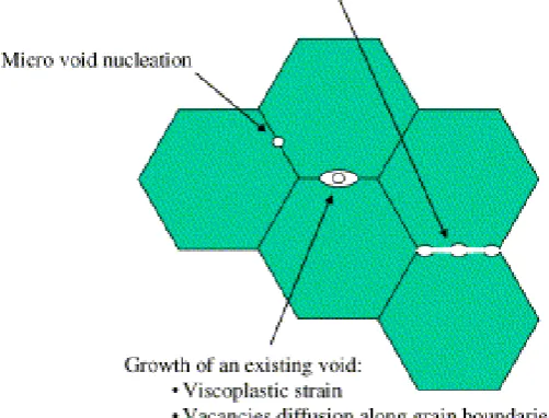
3.2 Micro-void mechanics based formulation
This formulation is physically based and takes into account nucleation, growth and coalescence of intergranular voids directly, as shown in Fig. 2. Recently, a set of such creep damage constitutive equations for austinitc stainless steel was developed by Michel (2004) and it considered:
• intergranular creep cavitation is represented by a continuum damage state variable f;
• intergranular damage rate Eq. (15)and coalescence criteria (16) are based on physical foundations (as much as possible);
• there are only two parameters (Vg, A) to fit nucleation and diffusion rates;
• a quasi unique identification of this two parameters can be derived from uniaxial creep tensile tests;
• the effect of stress triaxiality on damage rate and critical void fraction is explicitly defined in the model and does not need to be fitted.
t A f 3 V f f VM m f
g d d
2 3 sinh( 2 d
d ε )× ε + σ1
σ σ × +
= (15)
0 d d
d eq eq
eq
eq ∂ =
∂ + ∂ ∂ + ∂ ∂ = f f f f f
f ε ε
σ ε ε σ σ δσ (16)
where
V
gand A are material parameters. For the specific material they are 0.82 and 9x10-9.3.3 Thermodynamic formulation
There are significant more publications of creep deformation and creep damage constitutive equations, such as Lemaitre, Desmorat and Sauzay (2000), Voyiadjis and Zolochevsky (1998), Betten, Sklepus and Zolochevsky (1998), Voyiadjis and Zolochevsky (2000) and Zolochevsky and Voyiadjis (2005), to name a few. The research work has deal with hardening, anisotropic creep deformation and damage. For brevity and again, due to the space limit in the paper, they will not be cited and commented. Interested reader can refer them directly.
3.4 Discussions
Whilst appreciating the complexity of a set of creep damage constitutive equations, the following observations are made in order establish a precise understanding of the phenomena involved in creep deformation and damage for validation purpose:
1. How the creep damage in evolved under hydrostatic pressure case? More specifically, how creep damage is coupled with creep strain. It is necessary to be caution and to check any such coupling relation obtained from uni-axial test for multi-axial case;
2. The meaning of rupture and how to quantify it;
Fig. 2 Illustration of intergranular creep damage (Michel, 2004)
4. GENERIC VALIDATION STRATEGY
Validation of a set of constitutive equations is an important aspect and should be conducted before its general application in analysis. This is true for both creep damage mechanics and damage mechanics. Recently, Lemaitre and Desmorat (2005) have advocated Cross Identification of Damage Evolution Laws, Validation Procedure, and Sensitivity Analysis, within the context of Precise Identification of Material Parameters. The general validation procedure, not specific to and limited to creep damage, was outlined as:
• 2D or 3D state of stress measurements to check the criteria used
• Non-proportional tests to check the validity of the anisotropy representation
• Complex history of stress to check the representation of the damage accumulation
• Non-isothermal tests to check the representation due to the coupling between damage and strain behaviours
Earlier than and independent to the above general guide, Xu (2004) considered the adequacy for validation of a set of creep damage constitutive equations. In comparison with previous practice, it clearly pointed out that an adequate validation should address 1) what needs to be assessed and 2) under what conditions. Then, it was proposed that an adequate validation should be designed and conducted considering (Xu, 2004):
(1) The items
a) creep strain rate; b) damage evolution. (2) The stress states:
a) creep curves under uni-axial conditions;
b) multi-axial stress states under proportional loading conditions; c) multi-axial states of stress under non-proportional loading conditions.
On the other hand, the rate form constitutive equations can be integrated over time and the accumulated strain and damage could be used.
Ideally, the conditions should include proportional and non-proportional loading under multi-axial stress states. Compromise may have to be made due to the constraint imposed by the difficulty to conduct the required experiments and the cost involved, which is not the same as ignorance. Xu (2004) pointed out that previous practice was not adequate in either the items to be assessed or the range of states of stress.
A practical validation method was proposed by Xu (2004) as the following steps:
(1) To check isochronous rupture loci under plane stress and plane strain states with proportional loading conditions;
(2) To check strain at failure under plane stress and plane strain states with proportional loading conditions;
(3) To check typical creep curves under plane stress and plane strain states with proportional loading conditions;
multi-axial stress states complex (or non-proportional) loading condition. One way to achieve this is notched bar test.
In steps 1 and 2, the plane stress and plane strain stress states are selected to present multi-axial stress states under proportional loading conditions. It is suggested that all the material constants should be determined in the first two steps. Step 3 intends to further check the coupling of damage and creep strain. Step 4 validates the constitutive equations under multi-axial non-proportional loading conditions. It is clear that previous practice is not adequate as it ignored the need to include strain at failure under plane stress states with proportional loading conditions and did not consider plane stress states with proportional conditions. Furthermore, it also did not use damage development information. There was a reported discrepancy between predicted and observed damage development (Kobayashi et al., 1998).
More over, the author became aware of a number of papers in the following aspects such as: 1) damage concept and evolution, 2) non-classical and anisotropic creep deformation and creep damage constitutive equations, 3) continuum creep damage model based on nucleation, growth and coalescence of voids, and 4) multi-axial experimental data including damage distribution. The latest acquired knowledge has inspired, partially, to re-examine the formulation of creep damage constitutive equations and to expand the validation strategy in full. Furthermore, a total quality control approach is adopted.
The generic validation procedure for creep damage constitutive equations is proposed and expanded as the following four stages:
STAGE ONE Theories and Fundamentals: Critically assess the theories and hypothesis incorporated in a chosen type of creep damage constitutive equations which may include:
1.a The definition of damage concept and the rupture criterion in terms of physics and mathematics; 1.b The damage evolution law;
1.c The creep deformation theory;
1.d The physical base for generalization of the conclusions/observations based on uni-axial tensile test; 1.e The coupling between creep deformation and damage;
1.f The theoretical behaviours under plane stress, plane strain and tri-axial states of stress.
Here, it is a theoretical and qualitative assessment of the nature of a specific type of constitutive equations and the values for material parameters are generally not needed.
STAGE TWO Parameter Determinations: Critically assess the quality of quality of the process of obtaining material parameters which may include, not limited to:
2.a The optimization method: The quality of designed objective function; 2.b The coverage of stress levels and states and temperature of the input data;
2.c The coverage of stress levels and stress states and temperature covered by the experimental data base;
2.d The consistency of experimental data.
This could be viewed as good practice guide in obtaining material parameters. This aspect has been addressed by a number of publications and books. However, it is included here as part of total quality control exercise.
STAGE THREE Proportional Loading: Validate a specific set of creep damage constitutive equations under proportional loading condition which may include, not limited to:
3.a To check isochronous rupture loci under plane stress and plane strain states under proportional loading conditions;
3.b To check strain at failure under plane stress and plane strain states under proportional loading conditions;
3.c To check typical creep curves under plane stress and plane strain states under proportional loading conditions, particularly the pure compression;
3.d To check typical damage evolution under plane stress and plane strain states under proportional loading;
3.e To check the damage development, creep strain development, strain at failure and lifetime for multi-axial stress states complex (but proportional) loading condition.
STAGE FOUR Non-proportional Loading: Validate a specific set of creep damage constitutive equations under non-proportional loading which may include, not limited to:
4.a The loading history may include: tension under two levels of stress, tension followed by torsion, notched bar test;
4.b The lifetime;
4.e The evolution and distribution of creep damage.
Though it is difficult to experimentally quantify the damage evolution and damage distribution, it is emphasized that this part of validation must be conducted to satisfaction. Otherwise, the general applicability of a set of creep damage constitutive equations is not ensured and it should be revised.
5. APPLICATION OF VALIDATION STRATEGY
The above proposed generic validation strategy should be used as a guide. It could be used, in a narrow and conventional sense, for validation lifetime only. However, it is envisaged that its use could help to identify the overlooked problems and to improve the formulation. In the following section, its use is illustrated, mainly via RKH type constitutive equations.
Firstly, the very first set of questions in STAGE ONE may be asked as:
1) What is the definition and physical meaning of creep damage under uni-axial tension? 2) What are the difference and the relation between continuous degrading and sudden rupture? 3) Why the critical value ωf = 1/3? Should it be function of stress level and states?
The following statements are considered this set of questions: The damage variable and the exponational parameter υ were introduced for better describing the tertiary creep stage deformation. The final rupture is more of fracture nature and this is the reason for the suggestions of critical value of less than 1. Thus, it would be more physically correct if the critical value for rupture was linked with stress level, and then with states of stress, too, for multi-axial situation.
Secondly, further questions may be asked in STAGE ONE (e.g. 1.e) and the following observation may be summarized (Xu, 2001b and Xu, 2004) as:
1) the effective creep strain is controlled by von Mises stress; 2) creep damage is assumed as quasi-isotropic;
3) the creep rupture strength theory or creep damage equivalent stress is introduced to describe the damage evolution to achieve lifetime consistency;
4) the material constant is calibrated against lifetime within bi-axial states of stress with possible consultation of notched bar lifetime prediction;
5) the fundamental deficiency in this KRH approach is that the creep strain consistency requirement is not satisfied.
Armed with these observations, it is already clear that this KRH type formulation needs to be refined. In doing so, Xu (2001b) has proposed a new formulation where a rupture variable is introduced and it is a function of the creep damage and state of stress. This is generally in agreement with other constitutive formulations such as: 1) the damage variable is defined as the ratio of creep deformation energy dissipation; 2) the creep strain is divided in two parts; and 3) the phenomenological aspects of micro-void growth model (Michel, 2004). Critically assessing the theories and fundamentals in formulation is an ongoing research and further comparative study will be reported in due course.
Thirdly, the following observations were made in STAGE Three (e.g. 3.a. To check isochronous rupture loci under plane stress and plane strain states under proportional loading conditions; 3.b To check strain at failure under plane stress and plane strain states under proportional loading conditions) (Xu, 2004):
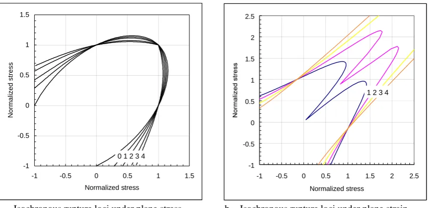
1) A significant creep strength increase under plane strain condition when the tri-axiality is about the order of 1.5–2.8 as shown in Fig. 3(b). This increase is not realistic according to well-known creep strength theory. Thus, the KRH formulation is unable to find a value for stress sensitivity that can satisfy the isochronous rupture loci under plane stress and plane strain conditions simultaneously. This deficiency was not be revealed in previous constitutive equation development and/or validation. The typical experimental isochronous rupture loci under plane stress are shown in Fig. 5 (Xu and Hayhurst, 2003) for comparison purpose.
2) The lifetime predicted under uni-axial tension and bi-axial equal tension is the same, which does not agree with the generally experimental observation.
3) Furthermore, the ratios of strain at failure for the previous formulation shown in Fig. 4 are conjugated with the shape of isochronous rupture loci shown in Fig. 3 through the common stress sensitivity parameter υ. Thus, there is no freedom provided to produce strain at failure consistent with experimental observation. This further demonstrates its incapability to predict consistently with experiment. The above three points have been addressed previously by (Xu, 2001b).
conduct validation Stages One to Three first and the conclusion may be drawn already like the one shown above; 2) seek cooperative and obtain experimental results from experimentalists.
As far as lifetime is concerned, it is a typical and conventional exercise. However, it is necessary to distinguish between calibration and validation, as reverse method has been used and notched bar tensile test was used for calibration. As far as for RHK type constitutive equations is concerned, the experimental lifetime of notched bar test was available and it was used, partially, for the determination of the value of υ during calibration. The difficulty experience reported by Perrin and Hayhurst (1996) should be examined fully.
As far as the damage evolution and distribution is concerned, the experimentally observed damage distribution (Kobayashi, et al, 1998) does not agree with numerical prediction based on KRH formulation.
Furthermore, the STAGE Three Parameter Determinations is left out as it has been adequately addressed originally.
The above illustrated validation exercise has shown the deficiencies of the exited KRH formulation and it suggests that further refinement/modification is needed. How to develop a better formulation is ongoing research and it will be reported in due course.
-1 -0.5 0 0.5 1 1.5
-1 -0.5 0 0.5 1 1.5 Normalized stress
N
o
rm
alized str
e
ss
0 1 2 3 4
-1 -0.5 0 0.5 1 1.5 2 2.5
-1 -0.5 0 0.5 1 1.5 2 2.5 Normalized stress
1 2 3 4
a. Isochronous rupture loci under plane stress b. Isochronous rupture loci under plane strain
Fig. 3 Isochronous rupture loci. The stress state sensitivity ranges from 1 to 4 with interval of 1.
The normalising stress
σ
0is 60 MPa.
0.1 1 10
-1 -0.5 0 0.5 1
Stress Ratio
Ra
ti
o
o
f S
tra
in
a
t F
a
ilu
re
0 1 2 3 4
0.01 0.1 1 10
-1 -0.5 0 0.5 1
Stress Ratio
0 1 2 3 4
a. Ratios of strain at failure under plane stress b. Ratios of strain at failure under plane strain
Fig. 5 Typical experimental isochronous rupture loci under plane stress (Xu and Hayhurst,
2003).
6. CONSLUSIONS
The following conclusions are drawn:
1) A generic validation methodology for a set of multi-axial creep damage constitutive equations is proposed.
2) The main contents for this method are: a) Theories and Fundamentals; b) Parameter Determination; c) Proportional Loading; and d) Non-Proportional Loading. It has been expanded significantly in comparison with previous preliminary version.
3) Its application clearly shows how to identify the hidden deficiencies of an existed formulation at various Stage One, Stage Three and Stage Four.
4) As the validation of Theories and Fundamentals has been included, any deficiencies in this aspect can be, hopefully, and has been identified, even without any actual experimental data. This is generic and important for practical purpose.
5) This also helps to suggest ways forward to develop or propose a refined formulation.
6) The proposed approach for validation contributes to the methodology for creep damage mechanics, as well as damage.
Further research on comparative study of formulations and validation exercise to micro-mechanics based continuum creep damage model will be conducted and reported in due course.
REFERENCES
Altenbach, H., Skrzypek, J. (Eds.), 2000. Creep and Damage Processes in Materials and Structures. Springer, New York.
Betten., J., 2005. Creep Mechanics. Springer, Berlin.
J. Betten, S. Sklepus and A. Zolochevsky, 1998. A creep damage model for initially isotropic materials with different properties in tension and compression. Engineering Fracture Mechanics, 59 5 (1998), pp.623-641. Boehler, J.P. (Eds.), 1990. Yielding, Damage, and Failure of Anisotropic Solid. Mechanical Engineering Publication Ltd., London.
B.J. Cane, Creep fracture of dispersion strengthened low alloy ferritic steels. Acta Metall. 29 (1981), pp. 1581–1591.
A. Cauvin and R. B. Testa, 1999. Damage mechanics: basic variables in continuum theories. Int. J. Solids & Structures, 36 (1999), pp.747-761.
D. Hayhurst, 1972. Creep rupture under multi-axial states of stress. J. Mech. Phys. Solids20 (1972), pp. 381–390. Hayhurst, D. R., 1984. Creep rupture under multi-axial states of stress. J. Mech. Phys. Solids, 20 (6), (1984), pp.381-390.
Hayhurst, D. R., Dimmer, P. R., and Morrison, C. J., 1984. Development of continuum damage in the creep rupture of notched bars. Phil. Trans. R. Soc. Lond., A311, (1984), pp.103-129.
Hayhurst, D.R., Miller, D.R., 1997. The use of creep continuum damage mechanics to predict damage evolution and failure in welded vessels. In: IMechch Seminar: Remanent Life Prediction. IMech Publication, London. Hayhurst, D.R., Xu, Q., 1997a. Summary of the preliminary results obtained from damage XX on crotch section idealisation of branch vessel with internal pressure 4 MPa. Research Report, Department of Mechanical Engineering, UMIST, Manchester, UK.
Hayhurst, D.R., Xu, Q., 1997b. Summary of the preliminary results obtained from damage XX on crotch section idealisation of branch vessel with internal pressure 4 MPa: Enhancement. Research Report for a HSE funded project, Department of Mechanical Engineering, UMIST, Manchester, UK.
Hayhurst, D.R., Xu, Q., 1997c. Summary of the preliminary results obtained from damage XX on flank section idealisation of branch vessel with internal pressure 4 MPa. Research Report for a HSE funded project, Department of Mechanical Engineering, UMIST, Manchester, UK.
Hayhurst, D.R., Xu, Q., 1997d. Summary of the preliminary results obtained from damage XX on crotch section idealisation of branch vessel with internal pressure 4 MPa: Enhancement. Research Report for a HSE funded project, Department of Mechanical Engineering, UMIST, Manchester, UK.
Huddleston, R. L., 1993. Assessment of an improved multi-axial strength theory based on creep-rupture data for type 316 stainless steel. J. Press. Vessel. Tech.115 (1993), pp. 177–183.
Janson, J and Hult J., 1977. Fracture mechanics and damage mechanics – a combined approach. J. de Mecanique Appliquee, 1 (1977), pp.69-84.
Kachanov, L. M., 1958. Time of the rupture processes under creep conditions, Izv. AN SSR, Otd. Tekh. Nauk, 1958, 8, 26-31.
Kachanov, L.M., 1986. Introduction to Continuum Damage Mechanic. Martinus Nijhoff, Dordrecht.
Kobayashi, K. K, Imada, H. and Majama, T., 1998. Nucleation and growth of creep voids in circumferentially notched specimens. JSME Series A41 2 (1998), pp. 218–224.
Kowalewski, Z. L., Hayhurst, D. R., and Dyson, B.F., 1994. Mechanisms-based creep constitutive equations for an aluminium alloy, J. Strain Analysis, 29(4), (1994), pp.309-316.
Krajcinovic, D., 1996. Damage Mechanics. Elsevier, The Netherlands.
Leckie, F. A., 1978. The constitutive equations of continuum creep damage mechanics. Phil. Trans. Roy. Soc., London A228, (1978), p.27.
Lemaitre, J., 1992. A Course on Damage Mechanics. Springer-Verlag, Berlin.
Lemaitre, J. and Chaboche, J.L., 1990. Mechanics of Solid Materials. Cambridge University Press, Cambridge. Lemaitre, J. and Desmorat, R., 2005. Engineering Damage Mechanics. Springer-Verlag, Berlin.
J. Lemaitre, R. Desmorat and M. Sauzay, Anisotropic damage law of evolution. Eur. J. A/Solids. 19 (2000), pp.187-208.
Michel, B., 2004. Formulation of a new intergranular creep damage model for austenitic stainless steels. Nuclear Engineering and Design,227 (2004), pp.161–174.
Murakami, S. and Ohno, N., (Eds.), 2000. IUTAM Symposium on Creep in Structures, April, 2000, Japan. Kluwer Academic Publishers.
M. Olsson, M. and Ristimaa, M., 2003. Damage evolution in elastic-plastic materials – material response due to different concepts. Int. J. Damage Mechanics. 12 (2003), pp.115-139.
I.J. Perrin and D.R. Hayhurst, Creep constitutive equations for 0.5Cr0.5Mo0.25V ferritic steel in the temperature range 600–675 °C. J. Strain Anal.31 4 (1996), pp. 299–314.
F.K.G., Odqvist and J. Hult, Some aspects of creep rupture. Arkiv for Fysik, 19, (1961), pp.37-82.
Spindler, M.W., Hales, R., Ainsworth, R.A., 1997. Multiaxial Creep-Fatigue Rules. IAEA/IWGFR Technical Committee Meeting on "Creep Fatigue Damage Rules to be Used in Fast Reactor Design", Altrincham, UK, 11–13 June 1996, published by IAEA, as IAEA-TECDOC-933, ISSN 1011-4289.
Skrzypek, J., Ganczarski, A., 1999. Modeling of Material Damage and Failure of Structures: Theory and Applications. Springer, Berlin.
Xu, Q., 2000a. The development of constitutive equations for creep damage behaviour under multi-axial states of stress. In: Selvadurai, A.P.S., Brebbia, C.A. (Eds.), Damage and Fracture Mechanics, vol. VI. WIT Press, 2000, pp. 435–445.
Xu, Q., 2000b. The development of creep damage constitutive equations under multi-axial states of stress. In: European Conference on Advances in Mechanical Behaviour, Plasticity and Damage, 7–9 November 2000, Tours, France, pp. 1375–1384.
Xu, Q., 2001a. The development of multi-axial creep damage constitutive equations for 0.5Cr0.5Mo0.25V ferritic steel at 590 °C. In: CREEP7, June 2001, Japan.
Q. Xu, 2001b. Creep damage constitutive equations for multi-axial states of stress for 0.5Cr0.5Mo0.25V ferritic steel at 590 °C. Theor. Appl. Fracture Mech.36 2 (2001), pp. 99–107.
Xu, Q., 2001c. The development of validation methodology and its further application to 0.5Cr0.5Mo0.25V at 590 °C. SMiRT 16, 2001.
Xu, Q., and Barrans, S., 2003. The development of multi-axial creep damage constitutive equations for 0.5Cr0.5Mo0.25V at 590 °C. JSME International Journal: Series A: Solid Mechanics and Material Engineering,
46 1 (2003), pp.51-59.
Xu, Q., 2004. The development of validation methodology and its further application to 0.5Cr0.5Mo0.25V at 590 °C. Nuclear Engineering & Design, 228 (2004), pp.97-106.
Xu, Q. and D. R. Hayhurst, 2003. The evaluation of high-stress creep ductility for 316 stainless steel at 550 °C by extrapolation of constitutive equations derived for lower stress levels. Int J Pressure Vessels and Piping, 80, 10, (2003), pp.689-694.
A. Voyiadjis and G. Zolochevsky, 1998. Creep theory for transversely isotropic solids sustaining unilateral damage. Mechanics Research Communication, 25 3, (1998), pp.299-304.
Z. Voyiadjis and A. Zolochevsky, 2000. Thermodynamic modelling of creep damage in materials with different properties in tension and compression. Int. J. Solids & Structures, 37 (2000), pp.3281-3303.