AT&T
MERLIN®
COMMUNICATIONS SYSTEM
ADMINISTRATION MANUAL:
MODELS 1030 AND 3070
MERLIN
Copyright © 1986 by AT&T Printed in U.S.A.
Table of Contents
How to Use This Manual Administration Overview
Administering Your System for the First Time Making Changes to Your System Later
MERLIN System Components
The Model 1030 Control Unit and Expansion Unit
The Administrator/Attendant Console Types of Consoles
Using the Console Optional Equipment
Preparing to Administer Your System
The Square vs. Pooled Decision About Square Systems About Pooled Systems The Forms and Labels You Need
Choosing a Time to Administer Your System
Basic Administration
Setting Your Control Unit Changing Your System Later
Notes on Resetting Control Unit Switches Entering and Leaving Administration Mode Specifying Touch-Tone or Rotary Signaling Setting Your System to Operate with the Call
Management System
Setting Up Square Systems
Notes on Assigning Lines to Voice Terminals Preparing to Assign Lines to Voice
Terminals
Assigning Lines to Buttons Setting Up Pooled Systems
Preparing to Set Up Line Pools Assigning Lines to Line Pools Preparing to Assign Lines to Buttons and
Set Up Access to Line Pools Assigning individual Lines to Buttons Assigning Line Pools to Buttons (Button
Access to Line Pools) Assigning Dial Access to Line Pools
Customizing with Additional System Options
Assigning Call Restrictions to Voice Terminals Assigning Outward and Toll Call
Restrictions
Setting Up Allowed Lists
Assigning Allowed-List Call Restrictions Administering Automatic Route Selection
(ARS)
How ARS Works
Overview of ARS Administration About ARS Tables
Page 2 4 4 6 8 8 11 11 14 15 16 17 17 20 23 23 24 25 27 27 28 29 30 31 31 33 33 35 35 36 37 41 42 4 3 4 5 4 6 4 7 4 9 5 1 5 3 5 3 5 4
Establishing Enhanced Night Service Administering Night Service with Group Assignment
Administering Night Service with Extra Alert Administering Night Service with Outward Restriction
Administering Night Service with Time Set Activating and Suspending Enhanced Night
Service with Time Set
Activating and Deactivating Enhanced Night Service at the Attendant Console Programming System Speed Dial Codes Administering SMDR (Station Message Detail
Recording) Options Resetting SMDR
Setting Your Printer to Scroll to the Top of the Page
Setting the Return Interval for Transferred Calls
Setting the Disconnect interval for Held Calls Setting the Recall Timer
Programming Voice Terminals for Office P r i o r i t i e s
Using Centralized Voice Terminal Programming
Assigning an Automatic Line Selection S e q u e n c e
Assigning Programmable Line Ringing for Incoming Calls
Assigning Cover Buttons Assigning Line Pickup Buttons
Programming Voice Terminals for Personal Priorities
Assigning Features to Programmable Buttons Feature Programming Chart
Assigning Personal Speed Dial Codes to 5-and 10-Button Voice Terminals 5-and Basic Telephones
Using Special Characters in Programmed Dialing Sequences
Selecting a Personalized Ring
Programming Voice Announcement Disable Programming Simultaneous Voice and
Data Calls
Special information about Attendant Consoles
Programming Tips for Attendant Consoles Notes on Programming and Using Economy
Attendant Consoles
Special Information about 5-Button Voice T e r m i n a l s
Page 8 6 86 89 90 92 94 9 5 96 99 101 1 0 1 1 0 2 1 0 3 1 0 4 1 0 5 1 0 9 1 1 0 1 1 1 1 1 2 1 1 4 1 1 5 1 1 6 1 1 7
How to Use This Manual
The advanced technology of the MERLIN® communications system offers a flex-ibility that allows you to customize the system to meet your particular business com-munication needs. As system administrator, you’ll probably be responsible for establishing the basic operating conditions of your MERLIN system immediately after installation. This includes such essential steps as setting the system to work with the Call Management System, if you have this automatic call distributor, and assigning lines to voice terminals.
You can also put optional systemwide features in place during your initial administra-tion session or add them later, depending on your priorities. If your needs change over time, you can easily alter your MERLIN system to meet the new requirements of your business.
This administration manual takes you step-by-step through the procedures involv-ed in customizing your system. Here is how to use the manual:
If you are setting up a new system for the first time:
1. Read the “Administration Overview," page 4, to learn about the tasks you’ll be performing as system administrator.
2. Review the “MERLIN System Components," page 8, to familiarize yourself with the equipment you’ll be working with.
3. If you haven’t already decided which features you want your MERLIN system to have, look through the “MERLIN System Features” described on pages 136 through 143.
4. Get ready to administer your system by filling out the System and Voice Terminal Configuration Forms on pages 144 through 180, if you haven’t done so already. You’ll also need to review the information in “Preparing to Administer Your System," page 16.
5. Read through “Basic Administration," page 24, and perform those tasks that apply to your particular system.
IMPORTANT If you plan to use the Call Management System (CMS) for
the MERLIN System, you must set your MERLIN system to be compati-ble with CMS before going on to other administration steps.
6. Similarly, read through “Customizing with Additional System Options," page 45, and add the systemwide features that your business needs. 7. Review the features described in “Programming Voice Terminals for
Of-fice Priorities," page 105. Because these features have systemwide effects, you should program the features on selected voice terminals yourself or oversee any programming done by voice terminal users.
8. If you want to assign features to voice terminals to suit the preferences of individual users, perform the procedures described in “Programming Voice Terminals for Personal Priorities” page 115.
9. To learn how to program your attendant console(s), review “Special infor-mation about Attendant Consoles,” page 127.
If you are changing some options or features that are already in place:
1. Review the information in “Preparing to Administer Your System," page 16. 2. Using the Table of Contents, Index, or page references in “MERLIN System Features,” page 136, locate the procedure for the option or feature you want to change and perform the necessary steps in the procedure. Streamlined instructions are provided in the “Quick Reference Guide to Administration Procedures” on page 183.
Administration Overview
Because the effects of system administration are wide-ranging, only you or someone you delegate should perform administration procedures. The term administer as used in this manual refers to the act of establishing certain options and features that have systemwide impact, such as assigning the outside lines that each voice terminal can access or defining System Speed Dial codes for everyone in the system to use. You use the switches on your control unit and the administrator/attendant console, the voice terminal connected to the intercom 10 jack on the control unit, to administer your system. Before you can perform administration, you have to put the system in a special state of operation called administration mode. (See “Entering and Leav-ing Administration Mode,” page 28, for more information about this operatLeav-ing state.)
In contrast, the term program refers to assigning programmable features to an in-dividual voice terminal. Anyone can put a voice terminal in programming mode and assign it features while the system is in the regular call-handling mode.
ADMINISTERING YOUR SYSTEM FOR THE FIRST TIME
System administration involves a series of simple procedures that you perform at the control unit and at the administrator/attendant console. The connections between the control units and the administrator/attendant consoles for Models 1030 and 3070 are illustrated below. The connection for Model 1520 is the same as that shown for Model 1030.
Model 1030 control unit
Voice terminal module jack 10
1
Administrator/Attendant console
Voice terminal module jack 10
Model 3070 control unit
The MERLIN system is designed to be up and running with a minimum amount of administration. However, certain administration procedures are required to set up newly installed system, depending on the conditions of your communications en-vironment and the options you choose. For example, if you want to use the Call management System (CMS) with your basic MERLIN system, you must administer your system to be compatible with CMS. Before performing any other procedures, review the information in “Basic Administration,” page 24, and complete the required procedures that apply to your system and business needs.
The other systemwide administration procedures are optional. You can administer just the features you want to use, at your own convenience. Those features are described in “Customizing with Additional System Options," page 45.
There are some features that you may want to assign to certain voice terminals yourself because they influence call-handling efficiency throughout your entire business. Assigning these features does not involve administrative procedures, but rather, simple programming steps at the administrator/attendant console or at in-dividual voice terminals. These procedures are described in “Programming Voice Terminals for Office Priorities,” page 105.
Finally, if you want to help people program their voice terminals to meet their individual needs, follow the procedures outlined in “Programming Voice Terminals for Personal Priorities,” page 115. Later, if your needs change, you can alter any system administra-tion or programming that has been done.
MAKING CHANGES TO YOUR SYSTEM LATER
Changing system features that were administered from the administrator/attendant console or programmed at individual voice terminals is a simple process. You just turn to the section of this manual that gives the procedure for assigning the feature or option you want, and follow the instructions. The “Quick Reference Guide to Ad-ministration Procedures” on page 183 provides streamlined instructions for program-ming systemwide features.
Making basic changes to the way your system operates—that is, changes to the switch settings on the control unit—is more complicated, since changing a setting may erase critical system administration that is now is place. Before you change any switch settings, review the information in “Changing Your System Later,” page 27.
Prepare for System Administration
These procedures help you get ready to administer your system.
● Decide how people will access outside lines.
● Complete and keep handy your System and Voice Terminal Configuration
Forms.
● Schedule a time to perform administration procedures.
Perform Basic Administration
Depending on your system requirements, some of these procedures maybe
necessary immediately after your system is installed; you also perform these
procedures whenever you need to change your system later. These procedures are carried out at the control unit and the administrator/attendant console.
● Set your control unit.
● Learn how to enter and leave administration mode. ● Specify Touch-Tone or rotary signaling.
● Set your system to work with the MERLIN Call Management System, if
your business has this automatic call distributor.
● Set up a square system, with lines assigned to buttons.
● Set up a pooled system, with line pools, line-to-button assignments, and
Customize with Additional System Options
These procedures are optional. Perform them at the administrator/attendant console whenever you want to add these features to your system.
● Assign call restrictions.
● Administer Automatic Route Selection.
● Assign voice terminals to groups for Group Page.
● Assign voice terminals to groups for Group Call Distribution.
● Establish One-Touch Hold with Call Announcement, if you want this feature
instead of One-Touch Transfer.
● Establish Enhanced Night Service. ● Program System Speed Dial codes.
● Administer Station Message Detail Recording options. ● Set return interval for transferred calls.
● Set disconnect interval for held calls. ● S e t r e c a l l t i m e r .
Program Voice Terminals for Office Priorities
These procedures are optional. Use Centralized Voice Terminal Programming or perform them at individual voice terminals whenever you want to give some-one access to these features.
● Assign an Automatic Line Selection sequence.
● Assign Programmable Line Ringing for incoming calls. ● Assign Cover buttons.
● Assign Line Pickup buttons.
Program Voice Terminals for Personal Priorities
These procedures are optional. Use Centralized Voice Terminal Programming or perform them at individual voice terminals whenever you want to give some-one access to these features.
● Assign features to programmable buttons.
● Assign Personal Speed Dial codes to 5- and 10-button voice terminals. ● Use special characters in programmed dialing sequences.
● Select a Personalized Ring.
MERLIN System Components
When performing your administration tasks, you work with three components of the MERLIN system: the control unit, the administrator/attendant console, and individual voice terminals. You may also have some optional equipment that adds teatures and capabilities to your system but does not affect system administration. The following descriptions will help you become familiar with the components that make up your system.
For information about system installation, refer to the /nstallation Guide: /Mode/s 1030 and 3070.
THE MODEL 1030 CONTROL UNIT AND EXPANSION UNIT
The Model 1030 control unit provides connections for up to 10 outside lines and 30 voice terminals, or for up to 15 out-side lines and 20 voice terminals, depending on the combination of Line and Voice Terminal Modules you choose. For a 1030 configuration, you have Line Modules in slots 7 and 8 (10 lines) and Voice Terminal Modules in slots 9, 10, and 11 (30 voice terminals). For a 1520 configuration, you replace the Voice Terminal Module in slot 11 with a Line Module. This increases the number of lines to 15 and decreases the number of voice terminals to 20.
The addition of an Expansion Unit makes the Model 1030 control unit a Model 3070 control unit and increases system capacity to as many as 30 outside lines and 70 voice terminals, again depending on the combination of Line and Voice Terminal Modules you choose. Similarly, a 1520 configuration can be changed to a 3070 configuration by replacing the Line Module in slot 11 with a Voice Terminal Module and adding an Expansion Unit.
1 2 3 4 5 6 7 8 9
1 .
THE MODEL 1030 CONTROL UNIT Power Module: Reduces ac power to a level the
system can handle.
l Circuit Breakers. Automatically cut the power to the control unit if an overload occurs. l Ring Generator connector. Optional Ring
Generator Unit plugs in here if you have basic Touch-Tone or rotary telephones.
● Auxiliary Power connector. Auxiliary Power Unit
plugs in hereto provide the additional power for systems with many optional accessories.
● Power light. Green light indicates power is on. ● On/Off switch. Turns the power to the control
2. Processor Module: Works in conjunction with Feature Module 5 to control system operating
conditions.
● Switches A, B, C, D, E, F, G, and H. Select
system options provided by Feature Module 5.
● Warning light. Red light warns of problem in
control unit. It also comes on for approximately one minute when you first turn on the system.
3. Feature Module 5: Contains the software that
con-trols your MERLIN system. You set eight switches on the Processor Module, according to the labels on the Feature Module, to select the following options from the programs stored in Feature Module 5:
● Attendant/Administer (10) option. Selects
at-tendant or administration mode of operation for the administrator/attendant console.
● NormaI/Attendant (11, 12, 13, 14) options.
Select normal or attendant mode of operation for these four voice terminals.
● Pooled/Square option. Selects mode of
opera-tion for the system so that line buttons on voice terminals represent either groups of lines (pooled) or separate lines (square). For detailed information on this option, see “The Square vs. Pooled Decision," page 17.
● Dial Access/Button Access option. Sets the
system so that a line pool can be accessed at a voice terminal either by touching the button to which the pool is assigned or by touching a Pool Access button and then dialing the access code for that line pool.
. 1-8 Lines/ 8 Lines option. Sets the system size to eight or fewer outside lines (small system) or to more than eight lines (large system).
4. Diagnostics Module (optional): Aids in identifying
faulty components if the system malfunctions.
5. SMDR (Station Message Detail Recording) Module (optional): Allows connection of a printer so you can
print out call traffic reports automatically as calls are made. The SMDR Module is also required for automatic operation of Enhanced Night Service with Time Set.
6. Services Module (optional): Contains the following
● Page jack. Connects a loudspeaker paging
system. With an adapter, you can have up to three paging zones.
● Music-In jack. Connects a music source for
Music-on-Hold or background music through a paging system.
● Bkgd Vol (Background Volume) control. Allows
volume adjustment for background music.
● MOH Vol (Music-on-Hold Volume) control.
Allows volume adjustment for Music-on-Hold.
● Page Sgnl switch. On (up) provides a short tone
before loudspeaker paging announcements. Off (down) eliminates the signal.
● Level switch. Sets amplification for music
source. Hi (down) is for sources with their own amplifiers; Lo (up) is for those without.
7. Line Module: Provides jacks for up to five outside
lines. Normally, there are two Line Modules in the Model 1030 control unit. You may have a third, however, if you decide to replace the Voice Terminal Module normally found in slot 11 with a Line Module in order to have 15 lines instead of 10 (1520 configura-tion). If you want to add an Expansion Unit, however, you must first return your control unit to the 1030 configuration.
The Expansion Unit contains up to four Line Modules. These modules, combined with two Line Modules in the 1030 control unit, provide the system maximum of six Line Modules (30 lines).
● Jacks O, 1, 2, 3, 4. Connect outside lines to the
MERLIN system. Line Modules have letters as well as numbers. For example, the first Line Module in the control unit is lettered A, so the jacks in that Line Module are called A0, A1, A2, A3, and A4.
8. Voice Terminal Module: Provides jacks for ten voice
terminals. You may have up to three Voice Terminal Modules for the Model 1030 control unit and up to four additional Voice Terminal Modules in the Expansion Unit. A Basic Telephone Module with jacks for basic Touch-Tone or rotary telephones is also available.
● “0” begins the numbering for the first five voice
Addition of the Expansion Unit changes the Model 1030 control unit to a Model 3070 control unit and increases overall system capacity to 30 lines and 70 voice terminals. The unit can accommodate:
● Up to two Power Modules ● Up to four Line Modules
● Up to four Voice Terminal Modules
The second Power Module is required for systems with more than 20 lines or more than 60 voice terminals. The Expan-sion Unit also has two additional module slots for future use.
NOTE: If you add an Expansion Unit to a system configured for 15 outside lines and 20 voice terminals, you must remove
the Line Module from slot 11 and replace it with a Voice Terminal Module. This returns your system to the standard con-figuration of 10 outside lines and 30 voice terminals. You can then insert modules into the appropriate slots in the Ex-pansion Unit.
If Expansion Unit slots 17, 18, 21, 22, and 23 are empty, the power switch on the first Power Module (slot 16) must be set to off (left). If modules are inserted in any of these slots, the power switch must be set to On (right).
If Expansion Unit slots 19, 20, and 24 are empty, the power switch on the second Power Module (slot 27) must be set to Off (left). If modules are inserted in any of these slots, the power switch must be set to On (right).
THE ADMINISTRATOR/ATTENDANT CONSOLE
The administrator/attendant console is the voice terminal connected to the intercom 10 Voice Terminal Module jack in the control unit. The console operates in either of two ways, depending on which mode you put it in.
● It functions as your primary attendant console under day-to-day call-handling
conditions.
● It functions as the administrator console when you use it to establish options
and features for the system as a whole or for individual voice terminals.
To change the administrator/attendant console from one mode of operation to the other, you just set a switch on the control unit and then set another switch on the con-sole itself. When the concon-sole is in administration mode, some of its buttons take on different functions than they have when the console is in the regular call-handling mode. Therefore, when you administer the system, you insert a special set of ad-ministration mode button labels in the console so that you know which buttons to touch. You’ll find two sets of button labels in the back of this manual. Which set you’ll use depends on the kind of administrator/attendant console you have.
Types of Consoles
The type of administrator/attendant console you have depends primarily on the number of voice terminals and lines in your system.
For systems with eight or fewer lines and 20 or fewer voice terminals (small systems— switch H on the control unit set to 1-8 Lines), you use the following console:
• The administrator/attendant console for small systems, a 34-button deluxe voice terminal
This model is suitable for small systems because it has enough buttons to show the status of each line and each voice terminal in the system. The system assigns lines and intercom numbers to these buttons automatically. You can use the lights next to each button to keep track of what is happening on the lines and at the voice terminals you are working with.
For systems with more than eight lines or more than 20 voice terminals (large systems—switch H on the control unit set to> 8 Lines), these two consoles are available:
● The administrator/attendant console with Attendant Intercom Selector for large
systems, a 34-button deluxe voice terminal with an attached Attendant Intercom Selector
Administrator/Attendant Consoles for
Small Systems* in Administration Mode
1. T/P switch: Set to P when performing system administration.
2. Adm Tel button: Used when assigning lines to voice terminals and assigning voice terminals Dial Access to Line Pools.
3. Adm Pool button: Used when setting up line pools.
4. Line buttons.
5. Auto Intercom buttons (10 through 29).
6. Adm Mist button: Used when specifying Touch-Tone or rotary signaling, assigning allowed-list call restrictions, and administering other system options.
7. Call Rstr button: Used when setting lines to detect a toll prefix or area code only and when assigning outward and toll call restrictions.
8. Message button: Used when giving a voice ter-minal the same assignments as one that has already been administered.
9. Conference button: Used to assign features to in-dividual voice terminals from the administrator/ attendant console.
Administrator/Attendant Consoles for
Large Systems* in Administration Mode
1. T/P switch: Set to P when performing system administration. 2. Adm Tel button: Used when assigning lines to voice terminals
and assigning voice terminals Dial Access to Line Pools. 3. Adm Pool button: Used when setting up line pools.
10. Shift button: Used to access Auto Intercom buttons for inter-com numbers 40 through 69.
Using the Console
If you have an administrator/attendant console for small systems, you’ll use Auto in-tercom buttons on your console to specify particular voice terminals during ad-ministration. If you have an administrator/attendant console with Attendant Intercom Selector for large systems, you’ll use Shift buttons along with your Auto Intercom but-tons. The paragraphs below describe how to use these butbut-tons.
Auto Intercom Buttons. Each person’s voice terminal has a unique 2-digit intercom
number similar to an extension number. These intercom numbers (10 through 39 for a Model 1030 system, 10 through 79 for a Model 3070 system) are automatically assigned to Auto Intercom buttons on the administrator/attendant console in small systems and in large systems where the administrator/attendant console has an Atten-dant Intercom Selector. During system administration you use the lights next to each Auto Intercom button to determine the status of voice terminals in your system.
The economy administrator/attendant console has no Auto Intercom buttons in the administration mode. With this console you use the dial pad rather than an Auto in-tercom button to specify a particular voice terminal.
Shift Buttons (console with Attendant Intercom Selector only). Consoles with
Attendant Intercom Selectors have three Shift buttons that let you administer as many as 70 voice terminals using only the 30 Auto Intercom buttons on the Attendant in-tercom Selector. When you touch one of the Shift buttons, you change the inin-tercom numbers assigned to the Auto Intercom buttons. Use the left Shift button labeled 10-20-30 to select intercom numbers 10 through 39 in the blue band, the center Shift button labeled 40-50-60 to select intercom numbers 40 through 69 in the white band, and the right Shift button labeled 70-80-90 to select intercom numbers 70 through 79 in the gray band.
If you want to dial a particular intercom number, you must first touch the Shift button that provides access to the group of intercom numbers that includes the one you want. For example, if you want to assign lines to the voice terminal represented by inter-com 31, touch the left Shift button. The light next to the Shift button inter-comes on, and the Auto Intercom buttons now represent intercom numbers 10 through 39.
It’s best to assign intercom numbers in the 10 through 39 range to people for whom an attendant handles many calls. The attendant can tell from which voice terminal a transferred call is returning if he or she transferred the call to an intercom number in the blue band.
Message Status Button (console with Attendant Intercom Selector only). The
OPTIONAL EQUIPMENT
You also may have optional equipment that adds features and capabilities to your system.
● Attendant Intercom Selector. Provides an attendant with 70 Auto Intercom
buttons.
● Basic Telephone and Modem Interface. Connects telephones and data
com-munication devices such as autodialers, answering machines, cordless telephones, facsimile machines, and auto-answer or originating modems to your
MERLIN system. You can also use a transformer to connect a timer to a Basic
Telephone and Modem Interface.
● Basic Telephone Module. Lets you connect basic Touch-Tone and rotary
telephones to the MERLIN system.
● Hands-Free Unit. Provides you with full speakerphone capability including
hands-free telephone conversation, On-Hook Dialing, Monitor-on-HoId, and teleconferencing.
● Headset and Headset Adapter. Enables an attendant to answer and listen to
calls without lifting the handset.
● General Purpose Adapter (for use only with 10-button and 34-button voice
ter-minals). Enables you to connect accessories, such as data terminals, cordless telephones, and autodialers, to a MERLIN system voice terminal.
● Off-Premises Telephone Interface. Connects off-premises telephones to your
Preparing to Administer Your
System
Before you start to administer your system, review this section to make sure you have the information and completed forms that you need.
Preparation Procedures
● Decide how people will access outside lines.
THE SQUARE VS. POOLED DECISION
For systems that have just been installed, you have to make a decision about a basic system characteristic— how people access outside lines with their voice terminals. You have the option of setting your system to be either square or pooled. In a square system, each outside line can appear on a separate button at each voice terminal. In a pooled system, outside lines are grouped together so that one button provides access to several outside Iines. On attendant consoles, however, each outside line appears on a separate button, whether your system is pooled or square, and you can-not change this arrangement.
Whether your system should be square or pooled depends on your specific business needs. If you want to use the Automatic Route Selection feature, your lines must be pooled and your system must beset for Dial Access to Line Pools. The characteristics of both configurations are discussed in greater detail in the paragraphs that follow.
About Square Systems
In the MERLIN communications system, Models 1030 and 3070 with Feature Module 5, a square configuration is one in which outside lines are represented by separate buttons on every voice terminal in the system. A square configuration simplifies call-handling because people can join in on calls or pickup calls on hold just by touching the appropriate line button at almost any voice terminal.
You can choose between two kinds of square configurations: standard or custom-ized. In the standard configuration, you give all voice terminals in the system access to the same lines. In the customized arrangement, on the other hand, you assign specific lines or sets of lines to selected groups of voice terminals. You can also assign personal lines to individual voice terminals in a customized square configuration.
Standard Square Configurations. The standard square configuration is ideal for
offices in which all staff members use the same lines to make and receive calls. In this arrangement, every line in the system appears at each voice terminal that has enough buttons to accommodate that number of lines. Depending upon the size of your system, you can assign up to 30 lines to as many as 70 voice terminals.
You will assign each of your lines to the same buttons at each voice terminal. To get the most from a standard square configuration, all your voice terminals should have enough buttons to handle all the lines in your system. If you have smaller capacity voice terminals, see “Special Information about 5-Button Voice Terminals,” page 131.
Lines are assigned to the same buttons at each voice terminal. EXAMPLE OF STANDARD SQUARE CONFIGURATION
Pages 31 through 34 explain how to assign lines to buttons on voice terminals in a standard square configuration.
Customized Square Configurations. In a customized square configuration, you
assign individual lines or groups of lines to selected voice terminals with similar re-quirements for placing and receiving calls. This arrangement lets you tailor your com-munications system to meet the needs of different departments. It also simplifies recordkeeping on calling patterns within your business.
A customized square configuration is the most appropriate system arrangement for Ultimate Motors’ varied communication requirements. The administrator assigns the three WATS lines and three of the eight local lines to the sales and clerical staff. The service department voice terminals get three different local lines and the Foreign Exchange line. The seventh local line is assigned to the voice terminal at the parts desk, and the eighth is assigned as a personal line at the manager’s voice terminal. The figure below illustrates this type of configuration.
Telephone Lines of Automobile Dealership
FX WATS Local Lines Line Lines
Service (Lines A, B, C, 1)
Parts (Line D)
Sales and office (Lines F, G, H, J, K, L)
About Pooled Systems
In a pooled configuration, you group several outside lines together into a pool that people can access with a single button on their voice terminals. When they place a call, they either touch the button assigned to a particular line pool (Button Access to Line Pools) or touch a Pool Access button and dial the code of the pool best suited for this type of call (Dial Access to Line Pools). The system then selects a free line from that pool, and the user dials the number he or she is trying to reach. If your system has Automatic Route Selection, users simply touch a Pool Access button and dial the number. The system routes the call automatically to the line pool specified by you, the administrator, for that type of call.
Your system can have as many as 11 different line pools. Each type of special-purpose line that your business has, such as WATS or Foreign Exchange (FX) lines, should be assigned to a separate pool. You should not mix types of lines in a pool because you cannot control which line people get when they access the pool. If your business has local lines, in-state WATS lines, and Band 1 out-of-state WATS lines, for exam-ple, you must set up at least three line pools.
When assigning lines in a pooled system, you can assign all, some, or none of your lines to a single pool (see diagram below), but you cannot assign any line to more than one pool. By the same token, you do not need to assign all your lines to pools; you can also assign individual lines that are not included in any pool to any voice terminal in your system. A diagram of a pooled system with eight lines appears on page 21.
Line B Line D
Line A Line C Line E
I I I
l
Lines A, B, C, D, E pooled
Lines A, B, C, D, E pooled
Intercom-Voice
Button Access vs. Dial Access to Line Pools. You can choose one of two access
options for line pools: Button Access to Line Pools or Dial Access to Line Pools. Because you set a switch for this option on your control unit, the method you select will be used at all the voice terminals in your system.
If you have only one or two line pools, Button Access is the best option for your system. If your system has several line pools, however, Dial Access is preferable because it provides access to all pools using only two buttons on each voice terminal. If you want to use Automatic Route Selection, you must select Dial Access. Dial Access is also necessary if you want basic telephones to have access to line pools or special lines or if you want 5-button voice terminals to have access to more than one special pool.
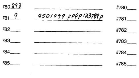
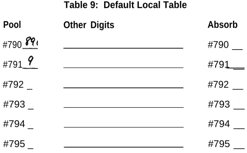
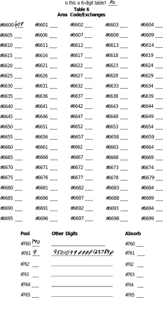
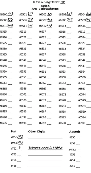
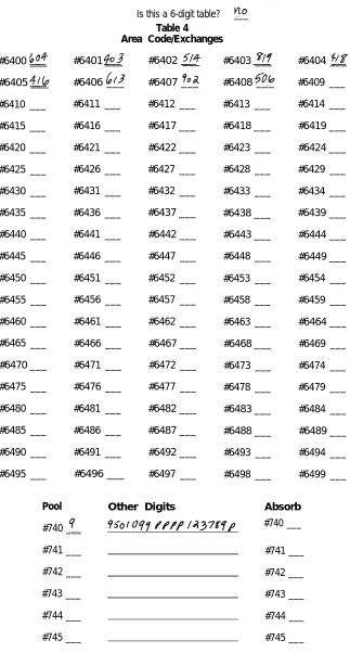
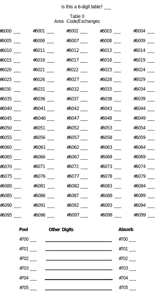
Dial code 893 = Line pool 5 Dial code 892 = Line pool 4 Dial code 891 = Line pool 3 Dial code 890 = Line pool 2 Dial code 9 = Main pool
DIAL ACCESS TO POOLS
Assume that you have five line pools. With the Dial Access option (see the diagram above), you arrange the system so that people can access any line pool by lifting the handset, touching one of the two buttons above Intercom-Voice, and dialing the access code assigned to the pool (9 for the main pool or 890 through 899 for the others). Even if you set your system for Dial Access, you can still assign some pools to particular buttons, if you like.
With the Button Access option (see the diagram below), people access all line pools directly through pool buttons on each voice terminal. In such an arrangement, the first two buttons above Intercom-Voice provide access to the main pool. You may assign additional buttons for access to other pools that may include WATS lines, FX lines, or lines used for special purposes.
Additional l i n e p o o l M a i n p o o l
THE FORMS AND LABELS YOU NEED
Before you begin performing administration procedures, be sure to complete all the necessary forms:
● A System Configuration Form to keep a record of how the lines in your system
are arranged.
● Voice Terminal Configuration Forms to record the lines and features assigned
to all voice terminals. Fill out one of these for each voice terminal.
When you ordered your system, you should have filled out these forms when you completed the MERLIN Communications System Planning Guide: Models 1030 and 3070 with Feature Module 5. If you did not, turn to the Appendix, photocopy the forms included there, and fill them out before you proceed further. These forms serve as important references throughout later system administration procedures.
During system administration the buttons on the administrator/attendant console per-form different functions than they do when the console is being used to handle calls. Therefore, you need a different set of button labels whenever you use the console for system administration.
Two sets of button labels for administrator/attendant consoles are provided in the back of this manual. One is for small systems (systems with switch H on the control unit set in the up position to 1-8 Lines), and the other is for large systems (systems with switch H on the control unit set in the down position >8 Lines). If you have an economy administrator/attendant console for a large system, you’ll use the labels for slots 1 through 4 only. If you have an administrator/attendant console with an Attendant In-tercom elector, you’ll use the labels for slots 5 through 7 as well.
Write in the telephone numbers of your outside lines on your administration mode button labels. If you have a small system or a large system with an Attendant Inter-com Selector, fill in the appropriate individual or group name for each interInter-com number as well. You may want to refer to your completed configuration forms as you fill in the button labels. Keep the button labels and completed configuration forms handy for use whenever you administer your system.
CHOOSING A TIME TO ADMINISTER YOUR SYSTEM
Basic Administration
Once your system planning and paperwork are complete, you can perform basic ad-ministration procedures. The chart below lists the procedures described in this sec-tion. Remember that if you are administering a new system that has just been in-stalled, some of these basic procedures maybe required to set the proper operating conditions for your particular environment, and you must perform them first before you goon to do any other system administration. Carry out the procedures in the order listed in the chart, but keep in mind that you may not need to perform all of them to customize your system to your particular environment. Read each procedure first to see if it applies to you.
IMPORTANT Administer your system at a time when you do not expect many peo-ple to be using their voice terminals.
Basic Administration Procedures
● Set your control unit.
● Learn how to enter and leave administration mode. ● Specify Touch-Tone or rotary signaling.
● If you want to configure your system to work with the MERLIN Call
Management System (CMS), set your system to be compatible with CMS.
● If you have a square system, assign lines to buttons on voice terminals. ● If you have a pooled system, set up line pools, assign individual lines and
SETTING YOUR CONTROL UNIT
The first step in customizing the MERLIN system is to set the control unit to the operating conditions you select.
IMPORTANT If your control unit has been set previously and you just want to
change the setting of a particular switch, be sure to read “Changing Your System Later,” page 27, before resetting that switch.
Follow these steps to set your control unit:
1. Turn off the control unit by setting the On/Off switch on the Power Module to Off.
2. Set switch A, which is located in slot 2 (color-coded purple) on the Pro-cessor Module, to Administer (down).
Switch A controls intercom number 10, which is always the main atten-dant position. Set switch A to the Administer position whenever you need to administer your system from the administrator/attendant console. When you finish administering, set switch A to Attendant (up).
NOTE: Switch A, which sets the mode of the administrator/attendant
console, is the only switch on the control unit that you can reset with the power on. If you reset any other switch with the power on, the con-trol unit does not recommend any of changes you make until you turn the power of, then on again.
3. Set Switches B through E.
Switches B through E control intercom numbers 11 through 14, respec-tively. These consoles normally function as voice terminals, but you can designate any of them as backup attendant consoles. If you designate a voice terminal to function as an attendant console, each outside line appears on a separate button, regardless of whether you select the pooled or square option.
The four voice terminals selected by switches B through E plus the administrator/attendant console (intercom number 10) provide a max-imum of five attendant consoles if you need them.
* For those voice terminals that function as attendant consoles, set the switch to Attendant (down).
* For those voice terminals that function as regular voice terminals, set the switch to Normal (up).
4. Set switch F.
* If you have chosen to pool your lines, set switch F to Pooled (up) and go to Step 5.
IMPORTANT: If you are changing Switch F from Square to Pooled
5. Set switch G.
NOTE: The instructions that follow apply if switch F is set to Pooled (up}.
If switch F is set to Square (down), switch G may be set to either posi-tion without having any effect on the system.
● If you have decided to arrange your pooled system so that people
can access line pools directly by simply touching the associated button on a voices terminal, set switch G to Button Access (down).
● If you have decided to arrange your pooled system so that people
can access any line pool by dialing the pool’s access code, set switch G to Dial/Access (up). You must set switch G for Dial/Access if you want to use Automatic Route Selection. Even if you set your system for Dial Access to Pools, you can still program buttons at individual voice terminals to provide one-touch access to particular line pools.
6. Set switch H.
● If you have eight or fewer outside lines and 20 or fewer voice
ter-minals set switch H to 7-8 Lines (up).
NOTE: The switch setting you select does not always have to
cor-respond to the number of outside lines you actually have. For ex-ample, if you have eight or fewer lines but plan to grow beyond eight lines within a year or two, you might prefer to set switch H to > 8 (down) in order to simplify readministering the system later. if you change the setting of this switch later, you cancel any special line administration of programmed features on your attendant consoles.
● If you have more than eight outside lines or more than 20 voice
ter-minals, or if you expect your system to grow to this size in the next year or so, set switch H to > 8 Lines (down).
7. If your system has an SMDR (Station Message Detail Recording) Module and a printer with an RS-232 connector, connect the printer to the SMDR Module (refer to the instructions that come with the module).
8. Turn on the control unit by setting the On/Off switch on the Power Module to On (right). This causes the system to record the changes you just made. The warning light on the Processor Module will go on. Wait for the light to go off before continuing. If you have a printer hooked up, a page header will be printed.
9. If your system has a Services Module, make the following adjustments. Otherwise, go to step 10.
● If you have background music through a loudspeaker paging
system, you can adjust its volume @turning the Bkgd Vol control clockwise to raise the volume, or counterclockwise to lower it. if you do not have background music through a loudspeaker pag-ing system, turn the control counter clockwise as far as it goes.
● If you have Music-on-Hold, you can adjust its volume by turning
the MOH Vol control clockwise to raise the volume, or counterclockwise to lower it. if you do not have Music-on-Hold, turn the control counterclockwise as far as it goes.
● lf you have a music source with its own amplifier, set this Level
switch to Hi (down); otherwise, set the switch to Lo (up).
● If you haves loudspeaker paging system and want a short tone
to precede loudspeaker announcements, set the Page Sgnl switch to On (up). Otherwise, set the switch to Off (down).
CHANGING YOUR SYSTEM LATER
Basic changes to the way your system operates—that is, changes to the switch set-tings on the control unit—may erase important system administration that is now in place. To change switch settings, turn to “Setting Your Control Unit," page 25, and follow the instructions for the switch you want to reset. Since you won’t be perform-ing the entire procedure, be especially careful not to skip any steps that are required. Follow the general instructions below to prevent this from happening.
General instructions for resetting control unit switches: 1. Set the On/Off switch on the Power Module to Off.
2. Set switch A to Administer (down).
3. Follow the instructions for the switch you intend to reset.
4. Turn the On/Off switch on the Power Module to On.
5. Perform any required readadministration or reprogramming discussed below in “Notes on Resetting Control Unit Switches.”
6. Set switch A back to Attendant (up).
Notes on Resetting Control Unit Switches
Whenever you change the setting of a switch on the control unit, you will probably have to make other changes in your system. Keep the following in mind:
● If you add or remove attendant consoles (switches B through E), you have to
reassign special lines and features to the voice terminals whose function you have just changed.
● If you change the setting of the Pooled/Square switch (switch F), you erase all
system line administration and voice terminal programming that was formerly in place. You have to completely readminister all your lines; setup pools and Dial Access to Line Pools, if these apply; and reprogram all your voice terminals.
● If you change the setting of the Dial Access/Button Access switch (switch G),
you must reprogram individual voice terminals accordingly. The system will automatically assign a different function to the two buttons above
lntercom-Voice. You must assign line pools to particular buttons (Button Access) or give
the voice terminal access to specified line pools (Dial Access). You must also assign individual lines to buttons.
● If you change the setting of the 1-8 lines/>8 lines switch (switch H), you cancel
any special line administration or programmed features on your attendant con-soles. The setting of this switch determines how the system automatically assigns lines and intercom numbers to the buttons on attendant consoles. It also determines the function of certain buttons on the attendant/administrator console when the console is in administration mode. (See “Initial Feature Assignments for Attendant Consoles," pages 129 and 130.)
ENTERING AND LEAVING ADMINISTRATION MODE
Administration mode is an operating state of your control unit and of your administrator/attendant console that is very different from their everyday state of operation. With the system in administration mode you are able to set up or change systemwide options or features. When you finish using the administrator/attendant console to administer your system, you must leave administration mode to resume normal attendant operations.
You must enter administration mode to set up a new system and again each time you use the attendant console to administer your system. The boxed instructions below tell you how to enter administration mode.
Entering Administration Mode
Switch A is located on the Processor Module (slot 2, color-coded purple) of the control unit. Set Switch A to Administer (down).
Insert the administration mode button labels provided at the back of this manual in the administrator/attendant console. Different sets are provided for large and small systems.
If the light next to Message Status is on, touch it once to turn it off before beginning to administer your system (large systems only).
Slide the T/P switch on the left side of the console to P.
Red and green lights start flashing next to the administration mode buttons labeled Adm Pool, Adm Tel, Adm Misc, and Call Rstr.
When you finish administration procedures at the console, you must leave administra-tion mode to resume normal operaadministra-tion. Do this when you complete your initial system administration and whenever you complete any system changes in the future. The boxed instructions below tell you how to leave administration mode.
Leaving Administration Mode
1. Slide the T/P switch to the center position.
2. Set switch A on the Processor Module of the control unit to Attendant (up).
SPECIFYING TOUCH-TONE OR ROTARY SIGNALING
When your system is installed, it is set to generate Touch-Tone signals. If some of your lines are rotary, you need to reset your system accordingly. If you have rotary lines or if you are not sure what type of lines you have, follow the procedure below. If all your lines are Touch-Tone, turn to the next page to continue administering your system.
To determine if your lines are Touch-Tone or rotary, go to the administrator/attendant console and make sure that the T/P switch is in the center position. Then touch each line button and dial out. If a line is Touch-Tone, you hear tones and the dial tone stops. If a line is rotary, you hear tones but the dial tone is not interrupted. Follow the pro-cedure below to specify Touch-Tone or rotary dialing.
1. If you have not already done so, enter the administration mode by following the boxed instructions on page 28.
2. Touch Adm Misc.
The lights next to the administration mode buttons stop flashing, and the green light next to the Adm Misc becomes steady.
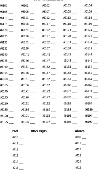
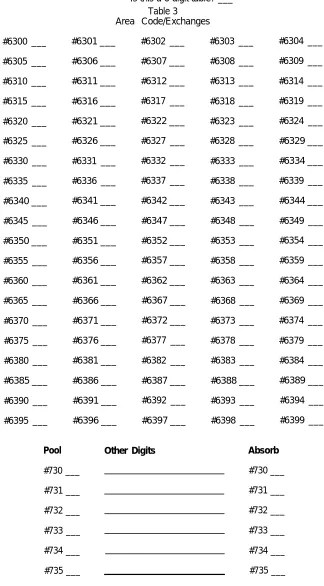
3. Dial the 4-character code #302.
4. One by one, touch the line button for each line in your system until the green light beside it shows the appropriate code. Each successive touch of a but-ton gives you one of the following codes:
Steady green light on = Touch-Tone signaling Green light off = rotary signaling
5. Touch Adm Misc again.
The lights next to the administration modes buttons flash.
SETTING YOUR SYSTEM TO OPERATE WITH THE CALL MANAGEMENT SYSTEM
If your business has the Call Management System (CMS) for the MERLIN Com-munications System, you need to set your basic MERLIN system to be compatible with this automatic call distributor.
If you do not have CMS, go on to the next section, “Setting Up Square Systems.” If you have CMS, follow the procedure below to set your system for operation with CMS or to change it from CMS to non-CMS operation. For details on configuring your
MERLIN system to work best with CMS, see your CSM documentation.
1. If you have not already done so, enter administration mode by following the boxed instructions on page 28.
2. Touch Adm Misc.
The lights next to the administration mode buttons stop flashing, and the green light next to Adm Misc becomes steady.
3. Dial the 4-character code #314, then perform one of the following operations
• To set your system to work with CMS, dial 1.
• To set your system to work without CMS, dial 0.
4. Touch Adm Misc.
The lights next to the administration mode buttons flash.
SETTING UP SQUARE SYSTEMS
In square systems, individual lines appear on separate buttons at voice terminals. If you want a standard square system, you will give all your voice terminals access to the same outside lines and assign the lines to the same buttons at every voice terminal. If you prefer a customized square system, you can assign different lines or groups of lines to selected voice terminals, in whatever order you want. If someone routinely carries on private telephone conversations, you may want to assign a per-sonal line to his or her voice terminal as part of your customized square setup. If you assign a personal line only to that voice terminal, calls will not ring at other voice ter-minals or at the attendant’s console.
The information that follows describes how to assign lines to buttons in square systems. (See page 17, “The Square vs. Pooled Decision,” for more information on square systems.)
Notes on Assigning Lines to Voice Terminals
Before you assign lines to buttons, take note of this general information:
● Even though you may not be using the full capacity of a Line Module in the
con-trol unit, all five of the lines that would be represented by that module are automatically assigned to buttons on the administrator/attendant console. This occurs in both small and large systems. A port with no line cord plugged into it is called a nonequipped line appearance, or “ghost line.” Remove any ghost lines from your administrator/attendant console so that these buttons can be used for custom features. To remove a ghost line, follow the procedure for remov-ing lines from voice terminals in “Assignremov-ing Lines to Buttons” on page 33.
If you have eight or fewer lines but have two Line Modules in the control unit, your system initially assigns ghost lines to the voice terminals in your system as well as to the administrator/attendant console. Remove these ghost lines from the voice terminals so that these buttons can be used.
● The Initial Feature Assignments diagrams on pages 129 and 130 illustrate the
order in which lines are assigned to buttons on the administrator/attendant con-sole when your system is first set up. The system automatically assigns lines to the buttons in the order in which the lines are plugged into the control unit. This is the “default” arrangement, that is, what your system does unless you specify something different, You can follow the procedure below to assign lines to buttons in a different order.
● When you assign a line to a voice terminal, the system automatically assigns
the line to the first button that doesn’t already have a line assigned to it, in the order shown in the diagram on the next page. You can assign lines to voice ter-minals in a different pattern by touching the line buttons in the order in which you want them to appear.
● Note that none of the voice terminals in your system come with preprinted
but-ton labels. Be sure to label the voice terminal butbut-tons with the telephone numbers of the lines you assign.
. Always assign lines to one voice terminal at a time.
● Make sure you have a completed Voice Terminal Configuration Form for each
voice terminal.
Order in Which the System Assigns Lines
in a Square System
3
8
9
2 0
2
7
10
21
1
6
11
2 2
Intercom-V o i c e
5
1 2
2 3
Intercom-R i n g
4
1 3
2 4
14
25
15
26
16
27
17
28
18
29
Preparing to Assign Lines to Voice Terminals
If you want to have a standard square system and have eight or fewer lines, your system has already been set up for you. The system automatically assigns the lines plugged into control unit jacks A0 through 62 to the eight line buttons above the dial pad on each voice terminal. If you have more than eight lines, however, you must follow the procedure below to assign the rest of your lines to each voice terminal in your system. The lines will be assigned to buttons in the order in which you touch them.
If you are setting up a customized square system for the first time, you should begin by removing all existing lines from each voice terminal in your system. If the primary attendant needs to have access to all general-use lines, remove from the ad-ministrator/attendant console only those lines that you are reserving for personal use. Follow the procedure below to assign lines to buttons on the voice terminals in your system. Remember that the lines will be assigned to buttons in the order in which you touch them.
NOTE: Later on in the administration process, you maybe assigning voice terminals
to Call Distribution groups. These are groups of employees such as customer ser-vice representatives or order-entry clerks who share responsibility for answering telephone calls. If you assign these people’s voice terminals to a Call Distribution group, the system directs each incoming call to the group member whose turn it is to take the next call. (For a detailed explanation of Group Call Distribution, see page 81.)
If you plan to associate outside lines with Call Distribution groups, keep these points in mind as you assign lines to your voice terminals:
● Any line that you plan to assign to a Call Distribution group must appear on a
button at every voice terminal in the group.
● Generally speaking, outside lines assigned to Call Distribution groups should
not appear on voice terminals outside the group. You can assign the lines to an attendant, however, if you want the attendant to answer calls when all the voice terminals in a group are busy.
Assigning Lines to Buttons
To assign individual lines to buttons in a standard or customized square system, follow the procedure below.
1. If you have not already done so, enter administration mode by following the boxed instructions on page 28.
2. Touch A d m T e l .
The light next to the administration mode buttons stop flashing, and the green light next to Adm Tel becomes steady.
5. Touch the appropriate line buttons to add or remove lines from this voice terminal. The green light next to each line button tells you the current status of the line. Each succesive touch of a line button gives you one
of the following codes:
Green light on = line is assigned to this voice terminal Green light off = line is not assigned to this voice terminal
The order in which you touch the line buttons determine the order in which lines appear on the voice terminal. For example, assume that eight lines (lines A0 through B2) are already assigned to voice terminal you are administering, and you want to add eight more. If you touch the line buttons in the order in which they appear on the voice terminal. If you touch the button for line C0 next, line C0 will appear on the button below the line C4 button, and so on. Be sure that the correct telephone number for each line appears on the associated buttopn on the voice terminal
6. Repeat steps 3 through 5 for each voice terminal to which you want to assign line.
NOTE: If you are setting up a customized square sytem, try to
admin-ister groups of voice terminal that share the same line assignments at the same time. If you plan to assign a personal line to a voice terminal,
be sure not to assign the line to any voice terminals that should not have access to that line.
You can use the shortcut below to give another voice terminal the same line assignments as one you have already set up. This procedures is especially timesaving if you have a standard square system, since all your voice terminals will have the same line assignments.
NOTE: When you copy line assignments, you also copy restrictions and
allowed-list permissions.
a. Dial the intercom number or touch the Auto Intercom button of the new voice terminal
b. Touch Message
The green light next to Message goes on.
c. Dial the intercom number or touch the Auto Intercom button of the original voice terminal
7. Touch A d m T e l .
The lights next to the administration mode buttons flash again. 8. Continue to administer your system or leave administration mode by
following the boxed instructions on page 28.
SETTING UP POOLED SYSTEMS
In pooled systems, you group similar types of outside lines into a line pool. A person with access to that line pool either presses a button or dials a code to get one of the interchangeable lines in the pool. For example, you might group five local lines into one pool, three in-state WATS lines into a second pool, and two cross-country WATS lines into a third pool. This would free several buttons on voice terminals that would otherwise be required for individual lines. If you decide to set up a pooled system, you will probably want to pool all your lines except single, special-purpose lines and those that are needed as personal lines.
To setup a pooled system, you begin by assigning lines to line pools. Next, you assign individual lines to buttons on voice terminals. If your system has Button Access to Line Pools, you also assign selected pools to particular buttons. If your system has Dial Access to Line Pools, you give each voice terminal access to the pools the user needs.
The following sections describe how to setup a pooled system. (See “The Square vs. Pooled Decision," page 17, for more information about pooled systems.)
Preparing to Set Up Line Pools
If you plan to pool the lines in your system, you must first assign individual lines to the appropriate pools. Before you set up your line pools, please read the informa-tion below.
● Even though you may not be using the full capacity of a Line Module in the
con-trol unit, the lines that would be represented by that module are automatically assigned to buttons on the administrator/attendant console. A port with no line cord plugged into it is called a nonequipped line appearance, or “ghost line.” Remove any ghost lines from the buttons to which the system assigned them on the administrator/attendant console so that these buttons can be used for custom features.
If you have eight or fewer lines but have two Line Modules, your system assigns ghost lines to your administrator/attendant console and places the ghost lines in the main pool. Be sure to remove any ghost lines from the main pool.
● You cannot set up line pools unless all the voice terminals in your system are
idle. Once you touch Adm Pool and see the steady green light that indicates you are free to administer your system, the system cannot place outgoing calls or receive incoming calls. Any callers will get a busy signal.
● Whenever you set switch F on the control unit to Pooled, the system automatically
assigns all your lines to the main pool. Local lines should remain in the main pool, but all other lines can be removed. You can assign lines that you do not want in the main pool to other pools or use them as individual lines.
● Do not mix different types of lines. For example, do not put regular telephone
lines and WATS lines in the same pool. Even within a WATS line pool, you can-not mix different bands of WATS lines or include both inbound and outbound lines. All lines in a pool must be interchangeable since you cannot control which lines people will get when they use the pool.
● The number of lines available for pooling is affected by the number of lines you
Assigning Lines to Line Pools
Follow the procedure below to set up line pools.
1. If you have not already done so, enter administration mode by follow-ing the boxed instructions onn page 28,
2. Touch Adm pool.
If your lines aren’t in use, the iights next to the administration mode but-tons stop flashing, the green light next to Adm Pool becomes steady.
The console gives a 2-beep signal for you to begin.
If this happens, go to step 4. If not, go to step 3.
3. If the green light next to Adrn Pool continues to flash instead of becom-ing steady and you don’t hear a 2-beep signal, your lines are in use. You cannot set up line pools unless all the voice terminals in your system are idle. To find out which voice terminals are busy, set the T/P switch to the center position.
Steady green lights show next to the Auto Intercom buttons for terminals that are in use.
If you want to proceed with setting up line pools, return the T/P switch to P touch Adm Pool again, and wait. As soon as the system is idle, the console gives the 2-beep signal for you to begin. Go on to step 4.
NOTE: If someone is on a data call, his or her voice terminal will not
show a busy signal. However, you will not be able to proceed with set-ting up line pools until that voice terminal is idle.
4. When you enter administration mode and touch Adm Pool, the system puts you in the main pool, the one that must contain your local lines. The main pool is Pool 9. Refer to your System Configuration Form to review the numbers that you assigned to the rest of your line pools. You must dial these access codes (890 through 899) in order to administer each of your line pools.
NOTE: if a line appears as an individual line at a voice terminal in your
system, it will disappear from that terminal if you add it to a line pool. Before adding lines to pools, make sure they are not needed as in-dividual lines,
If you want to administer the main pool, go on to step 5. If you want to administer one of your other pools, dial the access code for that pool, then go on to step 5.
5. Steady red lights appear beside each line that is assigned to this pool. Refer to your completed System Configuration Form to see which lines you want to have in the pool.
6. Touch the button of any line whose pool assignment you want to change. Each touch of the button gives you one of the following codes:
Steady red light on = line is assigned to pool Red light off = line is not assigned to pool
NOTE: If you hear a beep, the line is already in another pool. You must
remove the line from its current pool, by dialing that pool,s access code and touching the line button, before you can assign the line to a different pool.
7. To administer another pool, dial the appropriate access code (9 or 890 through 899) and repeat steps 5 and 6.
8. To make sure that your line pools are setup as you want them, dial the
9. Touch Adm Pool.
The lights next to the administration mode buttons flash again.
10. Continue to administer your system or leave administration mode by
Preparing to Assign Lines to Buttons and Set Up Access to Line Pools
You can assign individual lines and line pools to particular buttons on voice terminals and remove them from buttons whenever necessary, You can also assign individual voice terminals Dial Access to selected line pools. Before you begin assigning lines and line pools to buttons on voice terminals or assigning voice terminals Dial Ac-cess to Line Pools, please read the following information.
NOTE: If you plan to use Automatic Route Selection, you must set your system for Dial Access to Line Pools. The procedures for setting up Dial Access to Line Pools are presented on page 43.
● Always assign lines and line pools to one voice terminal at a time.
● Make sure you have a completed Voice Terminal Configuration Form for each
voice terminal.
● The Initial Feature Assignments diagrams on pages 129 and 130 illustrate the
order in which lines are assigned to buttons on attendant consoles when your system is first set up. The system automatically assigns lines to the attendant console in the order in which the lines are plugged into the control unit. This is the “default” arrangement, that is, what your system does unless you specify something different. You can change the order in which lines appear on the con-sole by following the procedure given below.
● Each line in your system must appear on a separate button at attendant
con-soles. If you assign a line pool to an attendant console, your system automatically assigns all the lines to buttons in the order in which they appear in the line pool. Be aware that you may change the positions of your lines on the attendant con-sole when you assign line pools,
For example, say that you set up two pools. Pool 9 contains lines 1,3, and 4 and Pool 890 contains lines 2, 5, and 6. Lines 1 through 6 initially appear on your attendant console in numerical order. If you assign Pool 9, then Pool 890 to the attendant console, however, the lines will appear in this order: 1, 3, 4, 2, 5, 6. If you change your line order by assigning pooled lines to attendant consoles, be sure to relabel your buttons to show the correct line numbers. If you remove a pool from the attendant console, remember that you remove all the lines in that pool.
● Remember that voice terminals cannot be administered and used at the same
time. You cannot assign lines and line pools to a voice terminal unless it is idle, and the user cannot place or receive calls while you are assigning lines. The voice terminal beeps softly while you are administering it as a reminder that it cannot be used.
● When you assign a line to a voice terminal, the system automatically assigns
Order in Which the System Assigns Lines and/or
Line Pools in a Pooled System
1
6
7
18
Pool
5
8
19
Pool
4
9
20
Intercom-Voice
3
10
21
Intercom-Ring
2
11
22
12
23
13
24
14
25
15
26
16
27
● Note that none of the voice terminals in your system come with preprinted
but-ton labels. Be sure to label the butbut-tons with the correct numbers for the individual lines and line pools that you assign to the voice terminal.
● If you set switch G on your control unit for Button Access to Line Pools, the system
automatically assigns Pool 9, the main pool, to the two buttons above
lntercom-Voice on voice terminals. If you set your system for Dial Access to Line Pools,
the system automatically assigns these two buttons as dial access buttons. Peo-ple will touch one of these buttons before dialing the number of the pool they want to use.
● When you assign a line in a pool to a particular button on a voice terminal, you
assign all the lines in that pool to that button. Therefore, if you want to assign a certain pool, such as a WATS line pool, to a separate button, you can do so by assigning any line in the pool to the button. You can do this whether switch G is set to Button Access or Dial Access.
● If someone regularly covers calls that come in on another person’s line (for
ex-ample, a secretary who answers someone’s perso