TM 5-304
TECHNICALMANUAL
ARMY FACILITIES
COMPONENTS
SYSTEM
USER
GUIDE
APPROVED FOR PUBLIC RELEASE; DISTRIBUTION IS UNLIMITED
HEADQUARTERS,
DEPARTMENT
OF THE ARMY
TECHNICAL MANUAL No. 5-304
* TM S-304
HEADQUARTERS DEPARTMENT OF THE ARMY WASHINGTON, D.C., 1 October 1990
ARMY FACILITIES COMPONENTS SYSTEM USER GUIDE
Paragraph Page
CHAPTER 1
CHAPTER 2
INTRODUCTION
Purpose ... l-l
Scope ... l-2
References ... l-3
Explanation of Abbreviations ... l-4
Background ... l-5
AFCS Publications ... l-6
Comments and Information Sources ... l-7
Inconsistencies, Errors, and Omissions ... 1-S
Responsibilities ... 1-9
Camouflage and Dispersal ... l-10
Bomb Damage Repair ... l-11
AFCS TERMINOLOGY AND DATA
AFCS ... 2-l
Building Blocks ... 2-2
Planning Table ... 2-3
Design Criteria ... 2-4
Construction Standards and Procurement Considerations ... 2-5
Types of Structures ... 2-6
Material Waste and Loss ... 2-7
Climatic Zones ... 2-S
Construction Effort ... 2-9
Engineer Unit Capabilities ... 2-10
Logistical and Cost Information ... 2-11
Operational Conditions ... 2-12
Storage and Transit Conditions ... 2-13
l-l
l-l
l-l
l-l
l-l
l-l
l-2
l-2
l-3
l-3
l-3
2-l
2-l
2-l
2-l
2-2
2-2
2-2
2-2
2-2
2-4
2-4
2-4
2-5
CHAFTER 3
CHAPTER 4
CHAF’TER 5
APPENDIX A
AF’PENDIX B
APPENDIX C
Paragraph
Site Orientation ... .2-14
Facilities for Initial Period (Up To 6 Months) ... .2-15
Facilities for a Temporary Period (Greater Than 6 Months) .... .2-16
OVERVIEW OF TM 5-301, TM 5-302, TM 5-303, AND THE TACAPS USER GUIDE
General ... 3-l
Use of TM 5-301 ... 3-2
Use of TM 5-302 ... 3-3
UseofTM5-303 ... .3-4
TACAPS User Guide ... 3-5
EXAMPLE PROBLEMS
General ... 4-l
Multiple Choice Problems (Table Consultation) ... .4-2
Simplified Lead-through Problems ... 4-3
UsingAFCSinPlanningandDesign ... .4-4
REQUISITION AND SUPPLY
Construction Supplies ... S-1
Requisitioning Procedures ... S-2
Methods of Shipment ... .5-3
Foreign Procurement ... .5-4
Materials Management ... .5-5
Functional Flowchart ... S-6
REFERENCES
Army Regulations ... A-l
Army Supply Catalog ... .A-2
Field Manuals ... A-3
Technical Manuals ... .A-4
Huntsvihe Division Manual ... A-5
CAMOUFLAGE AND DISPERSAL
Defensive Measures ... B-l
Camouflage ... .B-2
Dispersal ... B-3
BOMB DAMAGE REPAIR MATRIX ...
Page 2-5 2-5 2-6
3-l
3-l
3-2 3-3 3-3
4-l
4-l
4-2 4-6
5-l
5-l
5-2 5-2 5-2 5-2
A-l
A-l
A-l
A-l
A-l
B-l
B-l
B-2
C-l
TM 5-304
APPENDIX D CLIMATIC CONDITIONS
APPENDIX E
APPENDIX F
APPENDIXG
GLOSSARY
Figure Title Page
2-l Building orientation ... 2-6
3-l Example of an installation planning table ... .3-2
3-2 Exampleofafacilityplanningtable ... .3-3
3-3 Typical TM 5-303 entry ... .34
3-4 ExampleofaTOE ... .3-4
4-l Procedure for solving lead-through problems ... 4-3
4-2 Components of a 20-by-60-foot building ... 4-6
4-3 AFCS planning and design procedure flow ... 4-7
44 Calculations for project duration ... 4-11
5-l Requisition and supply process ... 5-3
B-l Dispersal heliport layout ... B-Q
B-2 Heliport layout, friendly air superiority ... B-5
B-3 Layout, all types of aircraft ... B-6
B-4 Fixed-wing aircraft layout ... B-7
Paragraph Page
Explanation of Climatic Terms . . . D-l
Temperate Zone: Intermediate Hot-dry and Intermediate Cold . . D-2
Tropical Zone: Wet-Warm and Wet-Hot . . . D-3
Frigid Zone: Cold . . . D-4
Desert Zone: Humid-Hot Coastal Desert and Hot-dry . . . D-5
ENGINEERING CAPABILITY TABLES . . . .
CONSTRUCTION DRAWINGS
D-l
D-l
. . .
D-5
D-5
E-l
Purpose . . . F-l
Types of Drawings. . . F-2
Symbols on Drawings . . . F-3
CPM NETWORK
Using CPM . . . G-l
CPM Symbols . . . G-2
CPM Example . . . G-3
F-l
F-l
F-6
G-l
G-l
G-3
... Glossary-l
LIST OF FIGURES
Figure
F-l
F-2
F-3
F-4
F-5
F-6
F-7
F-S
F-9
F-10
G-l
G-2 G-3 G4 G-5 G-6
Table 2-1 2-2 2-3 4-l 4-2 4-3
D-l
E-l
E-2
E-3
EA
E-5
Tirle Page
Typical site plan ... F-2
Typical electrical plan ... F-3
Elevation views ... F-4
Isometric views ... F-5
Typical floor plan ... F-7
Sectional drawings ... F-8
Details ... ..F- 9
Light framing details ... F-10
Typical wall panels-framing details ... F-11
Typical foundation and footing details ... F-12
Event numbers ... G-l
Circular logic error ... G-l
CPM network ... G-l
Example CPM diagram ... G-2
“Dummy” activity ... G-2
CPM diagram for a typical office building ... G-4
LIST OF TABLES
Title Page
Extra materials included for waste and loss ... 2-3
Ranges for operational conditions ... 2-4
Storage and transit conditions ... 2-5
Tabulations for example problem 5 ... 4-4
Tabulations for example problem 7 ... 4-5
Data for various construction components ... 4-10
Summary of temperature, solar radiation, and relative humidity extremes ... D-2
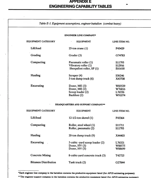
Equipment assumptions, engineer battalion (combat heavy) ... E-l
Engineer unit capability table, engineer battalion (combat heavy) 5-4152, .... E-2
Engineer unit capability table, headquarters and support company
engineer battalion (combat heavy) 5-416L ... E-3
Engineer unit capability table, headquarters and support company
engineer battalion (combat heavy) 5-41. ... E-4
Engineer unit capability table, engineer company
pipline construction 5-434L ... E-5
TM 5-304
Table
E-6
E-7
E-8
G-l
G-2
Title Page
Engineer unit capability table, engineer company port construction 5-603L . . E-6
Engineer unit capability table, engineer company dump truck 5-424L . . . . E-7
Engineer unit capability table, engineer company
construction support 5-4131, . . . . E-8
Construction activities for CPM example . . . . G-3
Tabulation of construction activities . _ _ . . . . G-5
CHAPTER 1
INTRODUCTION
1-I. PURPOSE
The purpose of this manual is to help personnel use the Army Facilities Components System (AFCS) and its products when preparing for and executing Army con- struction missions in a theater of operations (TO).
1-2. SCOPE
This manual is a single-source reference for the opera- tion of AFCS and available AFCS products. Example problems demonstrating the system’s use and informa- tion about requisition and supply procedures are in- cluded.
1-3. REFERENCES
Appendix A lists the references cited in this document.
I-4. EXPLANATION OF ABBREVIATIONS
Abbreviations and acronyms used in this manual are ex- plained in section I of the glossary. Abbreviations for construction materials are explained in section II of the glossary.
I-5. BACKGROUND
a. Definition. AFCS is a military engineering construc- tion support system for construction requirements in a TO. AFCS provides data to military planners so that they can prepare contingency plans and support estimates and specific design and logistics information for supply- ing, constructing, and maintaining facilities in a TO.
b. 17re NeedforAFCS. AFCS was designed in response to the vital need for an improved construction planning and supply system. Large inventory errors dis- covered at the close of World War II were basically caused by the supply system’s inadequate inventory capability. During the Korean Conflict, in the absence of a construction planning and supply system, TO planners lacked the resources needed to generate specific projects for base development. Thus, they were forced to use the World War II system of forecasting their needs for across-the-board items of construction material, primari- ly by reviewing the thousands of items in supply catalogs.
c. The Development of AFCS. Since its inception in 1951, AFCS has grown to include plamring guidance, detailed construction drawings, and computer updated bills of materials (BOM) for about 3,000 facilities. Some of the facilities included in the system are troop housing, hospitals, bridges, roads, supports, petroleum storage and distribution, and ammunition storage. The system is used:
l For joint, deliberate planning activities (Civil En-
gineer Support Planning (CESP) development).
l By major Army commands (MACOM’s) for theater
contingency planning, temporary construction projects, and engineer unit training.
l To support engineer contingency studies.
l To support operational projects.
l To determine contingency Class IV requirements.
l By the U.S. Army Training and Doctrine Command
(TRADOC) to support individual training.
l To support Army force development processes.
d. l7ze Automation of AFCS. The Theater Army Con- struction Automated Planning System (TACAPS) was developed in 1985 in order to provide a method for ac- cessing and using current AFCS design and logistics master files in a remote location. TACAPS requires the user to have a microcomputer system for accessing and using AFCS logistics information. TACAPS provides an automated method of identifying, maintaining, and dis- seminating information for construction planning in a TO or for contingency situations. TACAPS has the uni- que capability of generating theater facility requirements in terms of either specific AFCS facilities or gross meas- urement requirements (such as square feet, gallons, etc.) for deployable Army units based on either unit type codes (UTC’s) or standard requirement codes (SCR’s).
I-6. AFCS PUBLICATIONS
AFCS consists of a series of four Department of the Army (DA) technical manuals (TM’s). TM 5-304 and its companion manuals, TM 5-301, TM 5-302, and TM 5- 303, and the TACAPS User Guide are described briefly
TM 5-304
in paragraphs a through d below. Chapter 3 provides detailed instructions for using the manuals.
a. TM 5-301 Series, Army Facilities Components Sys- tem -Planning. The 301 series is generally used by military planners and contains installation, facility, and prepackaged expendable contingency supplies (PECS) summaries. TM 5-301 is published in four volumes: TM 5-301-1, TM 5-301-2, TM 5-301-3, and TM 5-301-4. Each volume addresses a separate climatic zone: temperate, tropical, frigid, and desert, respectively. PECS sum- maries and facility listings include (1) cost, shipping weight, and volume of material and (2) estimated man- hours needed to construct each facility and installation. The TM 5-301 series may be used by planners at higher levels without referring to TM 5-302 and TM 5-303 (see b and c below). The U.S. Atmy Engineer Division, Huntsville (USAEDH) maintains current summary infor- mation for the facilities and installations listed in the TM 5-301 manuals.
b. TM 5-302 Series, Army Facilities Components Sys-
tem -Design. The 302 series is a multivolume manual con-
taining design drawings for installations and facilities; it is of primary interest to the unit actually constructing AFCS facilities in a TO. TM 5-302 is updated when new facilities are added to the system, old ones are deleted, or revisions are made. The designs address the four climatic zones listed in paragraph a above and the two construction standards described in paragraph 2-5 below. The manuals are printed and initially distributed through the U.S. Army Publications and Printing Com- mand.
c. TM 5-303 Series, Army Facilities Components Sys- tem -Logistics Data and BOM. The 303 series is general- ly used by planners, builders, and supply personnel who need to identify items in the BOM. Each item in a facility (or PECS kit) is identified by a National Stock Number (NSN) and an abbreviated description. The material cost, shipping weight, volume, and estimated construc- tion effort in man-hours are also provided. USAEDH maintains current logistics information for the items in TM 5-303; the information is available in TM 5-303 for- mat.
d. CEHND 1105-l-1, TAWS User Guide. Provided upon request, the TACAPS User Guide is an AFCS specialty document that is not one of the official AFCS TM’s; however, it does contain instructions for accessing and using the computerized facility and installation
l-2
master files of AFCS information. Chapter 3 provides further information about TACAPS.
I-7. COMMENTS AND INFORMiTlON SOURCES
Data for the manuals are maintained by the U.S. Army Corps of Engineers (USACE). The data in TM 5-301 and TM 5-303 are available by direct computer access via printouts, magnetic tape, or diskette. The drawings in TM 5-302 are half-size (14 by 20 inches) reproducible drawings; those drawings are also available, upon re- quest, in full-size (28 by 40 inches) reproducible or blueline prints or computer input diskette for computer- aided drafting and design. All correspondence and re- quests for technical assistance, drawings, and
information regarding the AFCS system should be sent to either:
U.S. Army Engineer Division, Huntsville ATTN: CEHND-ED-SY
P.O. Box 1600
Huntsville, AL 35807-4301
or
HQDA (DAEN-ZCM)
Washington, DC 20310-2600
AFCS users are encouraged to submit comments and recommendations for improvement or revision directly to HQDA (DAEN-ZCM), Washington, DC. Comments should refer to the specific drawing, facility, or installa- tion. The reason for each comment or recommendation should be stated in order to ensure proper under- standing and evaluation.
I-8. INCONSISTENCIES, ERRORS, AND OMISSIONS
a. Design Reviews and Updates. AFCS is reviewed in order to isolate and correct inconsistencies and incor- porate changes in the design drawings and the BOM. Since design work has been carried out over a long period of time, updating and revising are continual.
c. Cost Data Updates. Cost data are accurate only at the time of issue. Those data are updated quarterly and can be obtained from USAEDH or accessed by micro- computer in accordance with TACAF’S procedures.
I-9. RESPONSIBILITIES
USACE continually reviews and updates this manual - a process that includes coordination with DA staff agen- cies, overseas commands, and other users affected by construction for contingency operations. AR 415-16 details the responsibilities of USACE and other agencies or commands.
l-10. CAMOUFLAGE AND DISPERSAL a. Camouflage. Camouflage is the technique of con- cealing or disguising military activities, materiel, and per- sonnel. It is used to gain the element of surprise and to reduce destruction of equipment and personnel casual- ties by enemy actions. Camouflage permits the move-
ment and placement of materiel and personnel without detection and gives the impression of being in a position or location that is not really occupied.
b. Dispersal. AFCS installation plans use minimum real estate and utilities and are based on functional relationships between facilities. Where dispersal is re- quired because of terrain features or expected enemy ac- tions, additional roads, utilities, and real estate must be added to the plans and constructed.
c. Further Information. See appendix B for specific in- formation about using camouflage and dispersal.
I-l 1. BOMB DAMAGE REPAIR
Regardless of how secure a camp may be, the possibility that all or part of a facility could be damaged by enemy actions must be considered. See appendix C for a bomb damage repair matrix of suggestions about repairing typi- cal bomb damages.
TM !J-304
CHAFlER2
AFCS TERMINOLOGY AND DATA
2-I. AFCS
AFCS is a system that helps all levels of military plan- ners, supply agency personnel, and construction person- nel who have a role in providing temporary Army facilities in support of contingencies.
2-2. BUILDING BLOCKS
AFCS uses a building block concept for maximum flexibility. Items, facilities, subfacilities, installations, and components, explained in paragraph a through e below, make up the building block system:
a. Item. An item is any construction material or equipment used to make up a facility. Each item has an associated NSN, description, unit of issue, and quantity. The following are examples of items:
l 5510-00-W-3964 Lumber Softwood Dim 2
Corn 2x4~12 BF (Qty)
l 53l5-00-W-5126 Nail Common 3d LB (Qty)
l 5530-00-262-8182 Plywood AI3 Ext 5 Ply
3/4x4&% in SH (Qty)
Tabulations of AFCS items required for each facility can be found in TM 5-303.
b. Facility. A facility is a group of items that provides a service. A facility can also be an item of equipment that enhances a function by providing specific physical assistance. Each facility is assigned and identified by a unique number. The following is an example of a facility description listed in TM 5-301-l:
14185AA Company Headquarters Building, 600 SF, wood construction, w/concrete floor, temperate climate
Each facility has an associated facility number, descrip- tion, unit of issue, shipping volume, shipping weight, and cost. Several facility numbers may be required to com- plete a functional facility. For example, constructing a finished and usable barracks building might require:
(1) The basic building.
(2) Additional bay (to extend building to some desired length).
(3) An insulation package.
(4) Electrical lighting and distribution package.
Users, therefore, should carefully read the facility description in TM 5-301 or TM 5-303 so that all neces- sary components are acquired.
c. SubfaClity. A subfacility differs from a facility only in its use in TM 5-303 (BOM). A subfacility reduces the repetitive listing of a facility? construction materials. When a facility is used as a subfacility, the entire subfacility is treated as one item of the major facility listed in the BOM. The subfacility’s name and a short description of it will appear in lieu of the NSN and shipping/logistics data for each of its items. The subfacility’s entire BOM will appear only where it is initially listed as a facility.
d Installation. An installation is a group of facilities designed to provide a specific service or support to a military function in a TO. Installations are listed in the Installation Planning Tables of TM 5-301 and in volume one of TM 5-302. Each installation has a unique associated number (two alpha and four numeric characters). For example:
l NT1131 Troop Camp, 250-man, temperate
climate, temporary standard
l DA1061 Ammo Storage, 12,000-ton capacity
for temperate climate
The shipping volume, shipping weight, cost, and labor re- quirements for each installation are also provided.
e. Component. Component is a generic term sometimes used to refer to any facility or installation in AFCS. It generally refers to one or more of the system’s building blocks.
2-3. PLANNING TABLE
A planning table is a tabulation of installation and facility logistical, cost, and engineering construction data from TM 5-301.
2-4. DESIGN CRITERIA
a. SiteAdaptation. Design assumptions and criteria, sometimes considered helpful for adapting a structure to specific site conditions, are shown in the working drawings of TM 5-302. Included is information such as maximum
stresses of structural members, assumed concrete strength, minimum soil-bearing capacities, and thermal (climatic) operating range. Those data can be used by qualified personnel to modify the proposed facility if materials or conditions differ from what is listed in the manual.
b. Sa$ety. Because of the short design life of the facilities, the minimum safety factors for ensuring personnel and equipment safety during the mission are used. Therefore, AFCS standard designs do not necessarily meet building codes.
2-5. CONSTRUCTION STANDARDS AND
PROCUREMENT CONSIDERATIONS
Construction standards are based primarily on the length of the contingency operation and are set by the theater commander. The following construction standards con- form to Joint Chief of Staff requirements and are in- cluded in the facility/installation descriptions printed in TM 5-301:
l Initial (INT) - up to 6 months.
l Temporary (TPR) - up to 24 months.
2-6. TYPES OF STRUCTURES
AFCS has two basic types of buildings: disposable and relocatable. Selection is based on mission requirements and resource availability.
a. Disposable. Wood frame, block, concrete, or any other material formed at the site and having little or no salvage value.
b. Relocatable. Pre-engineered, panelized buildings, or any other structure having S5-percent recoverability.
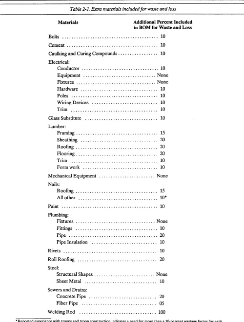
2-7. MATERIAL WASTE AND LOSS
Allowances are made for losses from breakage during handling and waste during cutting and fitting. Table 2-l lists the percentage of extra materials included.
2-8. CLIMATIC ZONES
In order to provide safe, effective, and habitable shelters, all AFCS designs take into consideration the climate of the facility’s intended use. AFCS facilities are designed to operate in one or more of four main climatic zones: temperate, tropical, frigid, and desert. Appendix D ex- plains those climatic zones in detail.
2-2
2-9. CONSTRUCTION EFFORT
The TM 5-301 series gives the estimated construction man-hours required to erect or construct each facility or installation. Those estimates are based on the use of standard construction practices and procedures promul- gated by the Engineer School; the estimates do not, how- ever, include administration, mobilization, planning, or work lost by weather delays. The estimates do include the actual construction time required for skilled and un- skilled personnel working in and major equipment operated in the temperate zone. Estimates for other climatic zones were obtained with the following adjust- ment factors:
l Temperate . . . 1.00 (base) l Tropical . . . 1.45 l Desert . . . .1.25 l Frigid . . . 2.41
The various categories of labor that may be involved in a project’s construction are described in paragraphs a through c below.
a. k$ticaI Labor: The vertical labor category includes skilled specialties such as:
l Carpenter/mason
l Electrician
l Plumber
l Diver
l Metal worker l Pipeline specialist
b. Horizontal Lubol: The horizontal labor category generally includes equipment operators such as:
l Lift/load equipment operator
l Construction equipment operator
l General construction machinery operator
l Dump truck operator
l Concrete/asphalt paving equipment operator
l Quarry machine operator
l Lightweight vehicle/power generator mechanic
c. General Labor: The general labor category includes all unskilled workers assisting horizontal or vertical laborers. General laborers perform tasks requiring no prior training or skill or use of mechanical or electrical
TM 5-304
Table 2-l. Extra materials included for waste and loss
Materials Additional Percent Included
in BOM for Waste and Loss
Bolts ... 10
Cement ... 10
caulking and Curing Compounds ... 10
Electrical: Conductor ... 10
Equipment ... None Fixtures ... ..Non e Hardware ... 10
Poles ... 10
W&g Devices ... 10
Trim ... 10
Glass Substitute ... 10
Lumber: Framing ... 15
Sheathing ... 20
Roofing.. ... 20
Flooring ... 20
Trim ... 10
Form work ... 10
MechanicA Equipment ... None Nails: Roofing.. ... 1.5 All other ... 10*
Paint.. ... 10
Plumbing: Fixtures ... None Fittings ... 10
Pipe ... 20
Pipe Insulation ... 10
Rivets ... 10
RollRoofing ... 20
Steel: Structural Shapes ... None Sheet Metal ... 10
Sewers and Drains: Concrete Pipe ... 20
Fiber Pipe ... 05
Welding Rod ... 100
*Reported experience with troops and troop construction indicates a need for more than a IO-percent wastage factor for nails.
Table 2-2. Ranges for operational conditions
Air Temperature Ambient Conditions Relative Solar Radiation Btu/f’t2/br
OF Humidity 9%
Temperate Zone:
Intermediate Hot Dry 70 to 110 24lto85 0 to360
Intermediate Cold -5 to -25 tending toward saturation negligible
Tropical Zone:
Wet Warm 75 95 to loo negligible
Wet Hot 78 to 95 74 to loo 0 to 360
Frigid Zone:
Cold -35 to 50 tending toward saturation negligible
Desert Zone:
Humid Hot Coastal Desert 85 to 100 63to90 0 to 360
Hot Dry 9oto125 5 to 20 0 to 360
2-10. ENGINEER UNIT CAPABILITIES a. Derivation of Pmductivity. Through the use of DA guidance, the productive capabilities of various engineer units have been estimated in terms of man-hours per month. The productive capabilities of various engineer units (summarized in appendix E) were derived by (1) deducting the nonproductive units from the overall number of units for administrative, maintenance, mess,
communication, and medical personnel and operators of administrative vehicles and (2) degrading the overall unit numbers by enemy actions and movement factors as shown in AR 570-2. The work period for all units is 10 hours per day, 7 days per week, 365 days per year. The functional skill groups listed in appendix E should not be interpreted as the sum total of skills available in the unit, but only as an indicator of unit capabilities. For more details on mission, assignment, and capabilities of each engineer unit, refer to FM 101-10-2
b. Reduced Prodxtivi@. The productive capabilities indicated in paragraph a above do not take into consideration several other aspects of unit capabilities. Additional reductions in the productive capabilities of engineer units can result from equipment processing following debarkation, area orientation, job organization, and acclimation of troops because of a change in climate and significant changes in altitude. As a conservative guide, productivity should decrease by 70 percent during the first 15 days when acclimation, equipment processing, area orientation, and job orientation are involved. When acclimation is not a factor, productivity should decrease by only 50 percent during the first 15 days.
2-I 1. LOGISTICAL AND COST INFORMATION
a. The material cost data and logistical data shown in TM 5-303 (BOM) are current as of the date of publication. Transportation costs for shipment are not included.
b. The user must be careful when unpacking materials
and equipment. The user should check for missing
materials immediately so that requisition procedures can be started, if necessary. Also, since the length of certain structural members is critical, components such as columns and certain roof truss pieces and roof and floor joists should be set aside in order to ensure that they are not cut up for use as smaller pieces. The user should also ensure that packing materials are removed carefully and not damaged, since those materials may be items (such as furring strips, etc.) needed for construction.
c. Aggregates for concrete cannot be requisitioned horn TM 5-303 (BOM). AFCS logistics data is based on the assumption that aggregates will be available within 5 miles of the construction site and can be acquired locally. Construction planners should ensure that necessary aggregates are available when the site is known.
2-12. OPERATIONAL CONDITIONS
Operational conditions are the climatic conditions to which personnel and materials may be subjected during military operations. Operational conditions are stated in terms of ambient temperature and humidity under stand- ard conditions of ventilation and radiation shielding. Table 2-2 lists the ranges of operational conditions for
TM 5-304
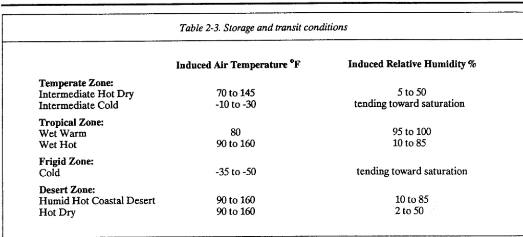
Table 2-3. Storage and transit conditions
Temperate Zone:
Intermediate Hot Dry Intermediate Cold
Tropical Zone:
Wet Warm Wet Hot
Frigid Zone:
Cold
Desert Zone:
Humid Hot Coastal Desert Hot Dry
Induced Air Temperature OF 70 to 145
-10 to -30
80
!3oto160
-35 to -50
90t0160 90to160
Induced Relative Humidity 5%
5to50
tending toward saturation
95 to loo 10 to 85
tending toward saturation
10 to 85 2to50
each climatic region. The temperature of any type of material may vary considerably from the operational temperature because of the effects of solar radiation, shading, internal heat sources, thermal mass, and heat- transfer characteristics.
2-13. STORAGE AND TRANSIT CONDITIONS
Storage and transit conditions are the air temperature and humidity conditions to which material may be sub- jected during storage and transit (such as inside a military-owned demountable container (MILVAN) or unventilated field storage shelter, under a tarpaulin in a tent, or in a railway boxcar). Table 2-3 gives the es- timated ranges of the induced temperature and humidity for each climatic region. Construction materials and equipment used in AFCS must be protected from prolonged exposure to adverse conditions.
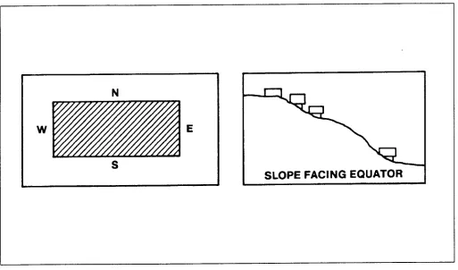
2-I 4. SITE ORIENTATION
a. Climatic Factors Building orientation can take advantage of natural attributes, such as solar heat gain (or shading), prevailing breezes for cooling, and placement of buildings on slopes facing the equator for added warmth in cold climates. Fiie 2-l demonstrates the passive use of climatic factors.
b. SiteAdaptation. Generally, AFCS installation plans assume a flat site; flat sites, however, rarely occur in the field. Therefore, it is necessary to perform a site analysis that considers factors such as slope, drainage, existing vegetation, access to and from the site, dispersal,
camouflage, and climate. AFCS utility design and the BOM are based on a specific layout on a flat site. Actual utility design must be based on actual site conditions with the BOM adjusted accordingly. Since the installation layouts provided are based on ideal conditions, the user must revise the layout, as required, based on the site analysis.
2-15. FACILITIES FOR INITIAL PERIOD (UP TO 6 MONTHS)
a. Facilities should be only those austere, quickly erectable, mission-essential facilities required to support the troops and their equipment.
b. Studies reveal that very few common construction
items will be acquired and delivered within the initial o-month period of a contingency operation. Therefore, construction material critical to mission success should be stockpiled by the appropriate MACOM and should be air-transportable or pre-positioned. Pre-positioning and local theater procurement are normally the best ways to ensure that materials are available when needed because high-priority logistics requirements for mission material and personnel are in effect early.
c. Operational planners for initial facilities should ensure that (1) the facility list includes only critical facilities, (2) air or sea transport will be made available, and (3) procurement, production lead time, and transport and erection time are adequate to support the operation plan. Normally, organic equipment and facilities and Common Table of Allowances (CIA) equipment and facilities should not be duplicated by AFCS facilities.
W E
S
SLOPE FACING EQUATOR
, .
Figure 2-l. Building orientation
d If delivered frost or pre-positioned, temporary relocatable buildings could be erected and used to protect initial and temporary materials, thereby increasing their in-theater life.
2-16. FACILITIES FOR A TEMPORARY PERIOD (GREATER THAN 6 MONTHS)
a. Temporary standards should provide a wider selection of minimum facilities, thereby increasing the efficiency, safety, durabiity, morale, and health standards of personnel on operations. Temporary standards are normally considered most appropriate in a secure Corn-2 area.
b. For local theater acquisition, the theater commander and logisticians should see what is available locally in the priority listed in (1) through (4) below:
(1) Using AFCS plans and the BOM, determine if materials are locally available or adapt AFCS designs to conform to the local building system.
(2) Use local off-the-shelf materials after determin- ing compatibility with organic, CIA equipment or other continental United States (CONUS) components.
(3) Use local materials that can be acquired or manufactured quickly.
(4) Use semipermanent approaches, such as lum- ber, brick, block, etc., that are common in the local area; also, use nationals skilled in working with the type of con- struction materials chosen.
c. For CONUS acquisition, the Standard Army supply systems should be used when any of the conditions in paragraphs (1) through (4) below exist:
(1) Needed materials are not available locally or supply is not dependable.
(2) Local economy lead times are in excess of Army Materiel Command (AMC) acquisition and delivery times.
(3) Local materials are not compatible with mis- sion equipment or requirements, i.e., 50-cycle electrical power versus 60-cycle electrical fixtures and material.
(4) Pre-positioning or the early execution of an operational project will satisfy all requirements for neces- sary construction materials in a timely manner.
TM 5-304
CHAPTER 3
OVERVIEW OF TM 5301, TM 5302, TM 5303,
AND THE TACAPS USER GUIDE
3-1. GENERAL
This chapter explains the purpose and content of each of the AFCS manuals. Also, for those who are not en- gineers, a brief section is included on the use of construc- tion drawings. Furthermore, since some new and typical AFCS designs will contain a critical path method (CPM) network, a brief section describing CPM and how it can be used to control actual construction is provided.
3-2. USE OF TM 5-301
a. Purpose. TM 5-301 is a planning document that
provides material costs and logistical and engineering data needed to plan theater construction. TM 5-301 is in- tended for use by those listed in paragraphs (I) through
(3) below:
(1) Contingency, base development, construction,
and logistical planners.
(2) Construction units (since the manual contains the engineering data required for construction of the various structures, facilities, installations, and utilities re- quired by the Army and Air Force for the support of military missions in the theater).
(3) Logistical commands and supply agencies for requisitioning, identifying, costing, and other related supply functions.
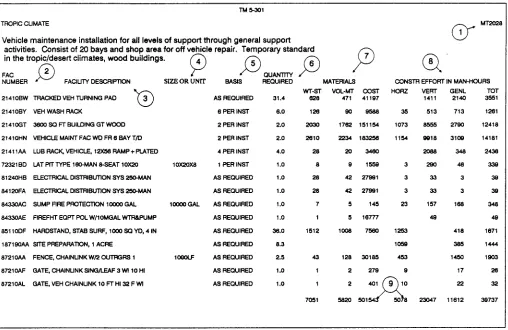
b. Installation Planning Tables. The term “planning tables” describes data published in TM 5-301 under the category of installations or facilities. (See figure 3-l for an example of an installation planning table.) Installa- tions are shown in the ascending order by the installation number in the upper right-hand corner, which consists of two alpha and four numeric characters (such as
ARl.511). The number identifies the complete BOM re- quired to construct that installation. The installation description appears in the upper left-hand corner and in- cludes the title, standard and type of construction, pur- pose, and other information as needed. The tables contain the items listed in paragraphs (I) through (9) below, which coordinate with the circled numbers in fig- ure 3-l:
(1) Drawing Number. TM 5-302, volume 1, con- tains the installation drawings, which are listed in the al- phanumeric sequence by installation numbers.
(2) Facility Number. Five numeric and two alpha characters identifying each AFCS facility (such as 21410BW). The five numeric characters are the con- struction category codes from AR 415-28.
(3) Facility Description. A brief description of the facilities included in the installation.
(4) Size or Unit. Dimensions, capacity, or unit of measure for each installation facility.
(5) Basis. The criteria or standard planning basis on which facilities are included in the installation.
(6) Quantity Required. The quantity needed of a particular installation facility.
(7) Materials. The total materials, logistics, and cost data associated with the number of facilities. Weight is shown in short tons (ST) ( 2,000 pounds) and volume in measured tons (MT) (40 cubic feet per measured ton).
(8) Construction Man-Hours. The estimated horizontal, vertical, and general construction man-hours.
(9) Installation Totals. The materials, logistics, and cost data and the construction effort totals shown at the end of each table. (Note that costs listed are current only at the time of publication.)
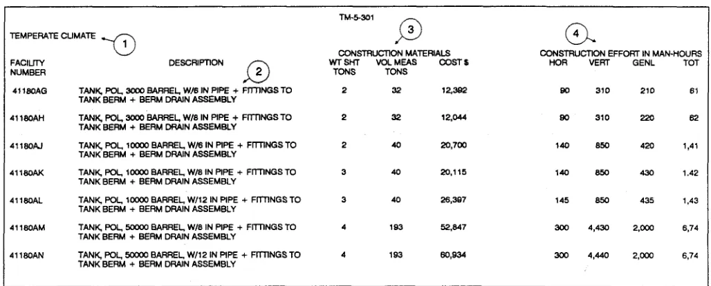
c. Facility Planning Tables. Another feature of TM 5- 301 is the facility planning tables (see figure 3-2 for an ex- ample). AFCS facilities are identified by their
application in a TO. The tables contain the items listed
in paragraphs (1) through (4) below, which coordinate
with the circled numbers in figure 3-2:
(1) Facility Number. Five numeric and two alpha characters that identify each facility (such as 41180AG). The TM 5-302 numbering system uses the entire facility number for the corresponding construction drawing; however, there is not a drawing for every facility number.
(2) Description. A detailed description of each facility. TM 5-303 provides a detailed BOM for each facility; TM 5-302 provides construction drawings and drawings for utilities (electric, sewage, and water).
TM-1 n?CPIC CUMA~
Vehicle maintenance installation for all levels of support through general support activities. Consist of 20 bays and shop area for off vehicle repair. Temporary standard in the tropic/desert climates, wood buildings.
0”
MT2u28
1
FAC D
2 p p $3 P a’
NUMBER FAClllM OESCRlFTlON SIZE OR UNn BASIS R”Z MATERIALS CCNSTR EFFORT IN MAN-HOURS -cl
WT-ST VOL.MT COST HORZ VERT GENL TOT 2141OBW TRACKED VEH TURNING PA0 3 AS REQUIRED 31.4 828 471 41187 1411 2140 3551 2141 OBY VEH WASH RACK BPERINST 8.0 128 a0 a58a 35 513 713 1261 21410GT 3EOOSQFTBUllMNGGTWCOO 2 PER INST 2.0 2u30 1762 151154 1073 8555 2780 12418 21410HN VEHICLE MAINT FAC WO FR 8 SAY T/D 2 PER INST 2.0 2810 2234 183256 1154 8818 3109 14181 21411AA LUBRAC~VEHICLE,12X56RAMP+F?ATEO 4 PER INST 4.0 28 20 3460 2ca8 348 2438 7232180 LATPiTTYPEl~MAN&SEAT10K2O loxzox8 1 PER INST 1.0 a 9 1559 3 290 46 338 8124OHE ELECTFllCAL OISTRlBUllON SYS 250.MAN As REQUIRED 1.0 28 42 27981 3 33 3 38 8412oFA ELECTRICAL MSTRiEU-TlCN SYS 250-MAN AS REQUIRED 1.0 28 42 27991 3 33 3 39 8433OAC SUMP FIRE PROTECTION loo00 GAL 1OOWGAL AS REQUIRED 1.0 7 5 145 23 157 188 348 34330AE FIREFHT EQPT POL W/lOMGAL WlR6PUMP AS REQUlRED 1.0 1 5 16777 4s 49 851lOOF HAROSTANO, STAB SURF, loo0 SC YO, 4 IN AS RECUIREO 36.0 1512 1008 7560 1253 418 1671
1871SOAA SITE PREPARATION, 1 ACRE AS REQUIRED 8.3 1WQ 385 1444
8721OAA FENCE, CHAINLINK W/2 CUTPGRS 1 lOGOLF AS REQUIRED 2.5 43 128 30185 453 1450 1903 EMlOAF GATE, CHAINUNKSINGAEAF 3 Wl 10 HI AS REQUIRED 1.0 1 2 279 9 17 26 B721OAL GATE, VEH CHAINUNK 10 FT HI 32 FWl AS REQUIRED 1.0 1 2 22 32 7051 !582u 501 11812 38737
Figure 3-1. Example of an installation planning table
(3) Construction Material. The logistics and cost data associated with each facility. The weight, given in short tons (2,000 pounds) includes packing material. The shipping volume is given in measured tons (40 cubic feet per measured ton). Costs are current as of the date of issue and are based on the Stock Item Master File (SIMF).
(4) Construction Effort in i&n-Hours. A list of the estimated engineer effort for horizontal, vertical, and general skills. The “total” column represents the sum of those items.
3-3. USE OF TM 5-302
a. General. TM 5-302 provides construction drawings to be used by military units in a TO. TM 5-302 contains installation layouts, facility plans, construction details, and lists of materials. The drawings consist of standard architectural/engineering working drawing elements. TM 5-302 is intended for use by:
(I) Base development planners determining facilities required to support Army functions.
(2) Engineer commands or units preparing and is- suing construction drawings.
(3) Construction personnel acquiring materials and doing the actual construction.
(4) Supply personnel identifying and supplying construction materials.
b. Construction Drawings. Appendix F briefly describes how to use the construction drawings.
c. CPM Networks.
(1) Network analysis is a method of planning and controlling projects by recording the interdependence of operations in a diagrammatic form so that each basic problem can be solved separately. Some important ad-
vantages of network analysis are listed in paragraphs (a)
through (d) below:
(a) Network analysis shows the interdependen-
ties between jobs, and enables people to see the overall plan and how their own activities depend on or influence the activities of others. Setting out the complete plan for everyone involved in the project makes assessment easier and helps prevent unrealistic or superficial planning.
TM 5-304
TEMPERATE CUMATE -0 1
FACILll-Y DESCRIPTION NUMBER
0 2 4116OAG TANK POL, 3000 BARREL, W/B IN PIPE + FllllNGS TO
TANK BERM + BERM DRAIN ASSEMBLY
4116OAH TANK POL, 3000 BARREL, W/6 IN PIPE + Frl-llNGS TO TANK BERM + BERM DRAIN ASSEMBLY
4116oAl TANK, POL. lWO0 BARREL, W/6 IN PIPE + FrlllNGS TO TANK BERM + BERM DRAIN ASSEMBLY
4116oAK TANK, pal, loo00 BARREL. W/6 IN PIPE + FllllNGS TO TANK BERM + BERM DRAIN ASSEMBLY
41160AL TANK, FOL. loo00 BARREL, W/12 IN PIPE + FllTlNGS TO TANK BERM + BERM DRAIN ASSEMBLY
4116OAM TANK, F’OL. 50000 BARREL W/8 IN PIPE + FITTINGS TO TANK BERM + BERM DRAIN ASSEMBLY
4116oAN TANK, POL, 50000 BARREL, W/12 IN PIPE + FITTINGS TO TANK BERM + BERM DRAIN ASSEMBLY
TM-5301
P
3
CONSTFlLJCllON MATERIALS WTSM VOL MEAS 5XT L
TONS TONS
2 32 12,382 2 32 12,044 2 40 20,700
3 40 20,115 140 6% 430 1.42
3 40 26,367
4 193 52,847 300 4,430 2.~ 6,74 4 193 60,934
o-.
4CONSTRUCTION EFFOFIT IN MAN-HOURS HOR VERT GENL TOT
so 310 210 61
Bo 310 220 62 140 650 420 1.41
145 650 435 1,43
300 4,440 w3J 6.74
Figure 3-2. Example of a facility planning table
(b) Resource and time constraints can be in-
cluded in the plan before its evaluation. An example of a resource constraint would be several operations requir- ing a crane, but only one crane is available. An example of a time constraint would be a minimum delivery period for materials (such as long lead-time items).
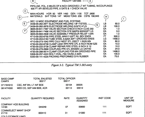
d. Materials. Logistical data, including shipping weight, volume, and costs.
(c,J Stricter controls can be used, since any deviation from the schedule is noticed quickly.
(d) If the completion date must be advanced, at- tention can be concentrated on speeding up only the few critical jobs. Then resources are not wasted on speeding up noncritical jobs.
(2) Appendix G explains specific steps and details for developing and using CPM networks.
e. BOMSection. Structural component breakdown. JY NSN. A unique number, assigned by the Depart- ment of Defense (DOD), that identifies the item.
g. Item Description. A general description of an item.
h. Unit oflssue. The smallest quantity per issue, such as each, linear foot, pound, package, etc. (See section II of the glossary for abbreviations.)
i. Quantity. Amount pf material required to construct the facility, including allowance for breakage, loss, and cutting to lit.
3-5. TACAPS USER GUIDE 3-4. USE OF TM 5-303
TM 5-303 is generally used by planners, builders, and suppliers in order to identify facility construction materials. A portion of a typical page in TM 5-303 (see figure 3-3) contains the information listed in paragraphs a through i below, which coordinate with the circled let- ters in figure 3-3:
a. The TACAPS User Guide explains how to use TACAPS effectively. The Huntsville Division TACAPS point of contact will provide system diskettes and specific user information upon request.
a. Facility Number. Five numeric and two alpha char- acters that identify each AFCS facility (e.g., 54OlOAW).
b. Building Description. Information about frame type, roofing and siding material, climatic zone, and dimensions.
b. The user can install TACAPS on a personal com-
puter by following the instructions provided with the dis- kettes and the specific user information contained in the TACAPS User Guide. User-friendly menus help the user access the facility and installation files in order to get current TM 5-301 and TM 5-303 information and use the tables of organization and equipment (TOE’s)/facil- ity base-camp planning module. Figure 3-4 shows an a sample of a TOE/facility computation.
c. Man-Hours. Construction estimate in vertical, c. The TOE/facility module enables the planner to
general, and horizontal construction in terms of man- develop specific base camps that are tailored to TOE or-
hours. ganization requirements. The facility makeup for a
0
I3
FACILITY 12510BE \PIPELINE, POL, 5 MILES OF 6 INCH GROOVED LT Wl TUBING, W/COUPLINGS
CL
500 FT API BEVELED PIPE, 5 GATE & 1 CHECK VALVE C
MAN-HOURS HOR 50 VER 1450 GEN 1100 TOT 2600
0
D - MATERIALS SHTTONS 147 MEASTONS 239 CST$ 158,943 0”SEC 12 MISC EQUIPMENT AND FUEL SYSTEMS Q D
E 343400-262-2671 ELECTRODE WELDING l/8” F/STEEL
d
34-262-2678 ELECTRODE WELDING 5/32”X14”LG +-@ ki 1%:
ml-7487 VALVE SECTION CHECK 6 INCH CLAS 250 EA 1.0
F ml-7488 VALVE SECTION GTE 5COPSI 6OlNX3FT LG EA 5.0
3835-00-6Q3-4506 VALVE ASSEMBLY PRESSUR RELIEF 1/2lN EA 1.0
471~202-6755 PIPE STEEL 6lNX17-22FT R/L BEV ENDS Fr 500.0
47lO-C0-203-0183 TUBE STEEL 6.625X 2UFf GROOVED ENDS LG 1456.0
4710-@273-1042 PIPE CULV NEST STL PSECT 1.5X25.5lN 80.0
473O-CXIb202-6739 CLAMP LEAK RPR PIPE CPL 6 INCH NOM SZE E 10.0 473O-GO.2223739 CLAMP REPAIR PIPE STEEL 6 INCH X 12
473C4lO-278-2669 COUPLING PPE STL 61NX6lN LG UNTHD z
10.0 24.0 4730-00-288-9514 CLAMP COUPLING FOR 61N GROOVED PIPE
5306-00-257-4224 BOLT OVAL,.750-lOUNC,45OIN 533CK10-141-4225 PACKING PREFORMED SYN RUBBER
Figure 3-3. Typical TM 5-303 entry
1498.0
E loo.0
EA 75.0
1 BASE-CAMP TOTAL ENLISTED TOTAL OFFICER
CAMPX 00217 ocm7
07178HOlO CSC, INF BN, LT INF BDE 00104
08147HCOO MED CO, SEP AIM BDE, ACR 00113
FACILITY QUANTITY REQUIRED RATE
COMPANY HQS BUILDING 14185
COMM/ELECT MAINT SHOP 21710
COLD STORAGE (UNIT) 43210
COVERED STORAGE (UNIT) 44220
TROOP HOUSING, ENLISTED 7211
044249
ooo410
000108
015624
07
01
02
02
08
cm05 oco12
QUANTITY INST CODE UNIT OF
ASSIGNED MEASURE
111 SQFT
OlooO 111 SQFT
00150 111 cum
111 CUFr
01872 111 SOFT
J Figure 3-4. Example of a TOE
developed base camp is determined via computer by puter the standard requirements code or unit code and
using DOD criteria for each construction category code the quantities for all planned TOE units. All require-
(AR 415-16) and the personnel/equipment makeup of ments are integrated into a single camp plan, and the
the selected TOE organizations as identified in the ap- camp list of quantities required at specific AFCS
proved TOE master files. The computer results include facilities can then be generated. The planner has the op-
equipment line item numbers, military occupational tion of deleting, adding, or changing any facility on the
specialty numbers, and enlisted personnel and officer list and producing the TM 5-301 or TM 5-303 items for
head count. The planner simply enters into the com- the developed camp facilities.
TM 5-304
CHAPTER4
EXAMPLE PROBLEMS
(b) If one NT1531 costs $516,813 and one NT1231 costs $44,242, then:
$516,813 + 2($44,242) = $605,297 for 1,750 personnel
(c) If one NT1531 costs $516,8l3 and one NT1131 costs $71,271, then:
$516,813 + 3($71,271) = $730,626 for 1,750 personnel
Although ah of the installations can meet the 1,700-per- son capacity requirement, choice (b) is the least expen- sive. The estimated construction effort for thii
combination would be:
I
Construction Effort in Man-Hours4-1. GENERAL
Several example problems have been developed in order to demonstrate the use of AFCS for military planting, design, etc. The problems range from simple data extrac- tion from the various manuals to a complex planning problem. Since AFCS is an extensive system with a broad range of facihty types, it is not possible to cover all avail- able facilities; however, the general procedures for using the system are the same for all facihty types. Therefore, the example problems in this chapter should provide ade- quate guidance:
4-2. MULTIPLE CHOICE PROBLEMS (TABLE CONSULTATION)
The purpose of these problems is to (1) familiarize the user with the AFCS installation and facility numbering systems and (2) teach the user how to extract component data from the various manuals. The problems
demonstrate how facilities and installations can be com- bined to meet any desired function; they also show the user how to select the components that best meet a function’s requirements.
a. Example problem 1.
b. Example Problem 2.
(1) Problem Statement. A troop camp must house 1,700 military personnel in the temperate zone (tem- porary standard of construction). Which of the combina- tions of instahations listed in (a) through (c) below will meet that requirement for the least cost? What will be the estimated construction effort required?
(a) lb0 NT1531
(1) Problem Statement. A hospital having at least a 700-bed capacity is required in the temperate zone (initial standard of construction). Which of the in- stallations or combinations of installations listed in (a)
through (c) below can meet that requirement with the least effort?
(a) One GH0521 and two GH0121
(b) One GH0521 and one GH0221
(c) One GH0721
(b) One NT1531 and two NT1231
(c) One NT1531 and three NT1131
(2) Solution. Determine the cost of each installa- tion from data in TM 5-301-l. (Note that shipping costs, the costs of hiring civilian labor, etc., are not included.) Also, verify the capacity of the cantonment.
(a) If one NT1531 costs $516,813, then:
$516,813 x 2 = $1,033,626 for 2,000 personnel
(2) Solution. Obtain cost information from the in- stallation section of TM 5-301-l. AIso, verify the hospital’s required capacity. Calculate the man-hours (MH’s) in order to find the least construction effort.
(u) If one GH0521(500 beds) takes 28,021 MH and GH0221(100 beds) takes 14,184 MH, then:
28,021 MH + 2 (14,184 MH) = 56,389 MH for 700 beds
(b) If one GH0521(500 beds) takes 28,021 MH
and one GH0221(200 beds) takes 14,483 MH, then:
28,021 MH + 14,483 MH = 42,504 MH for 700 beds
1. Costs and man-hours used in the examples may not be current but are valid for comparison purposes.
(c) If GH0721(750 beds) takes 33,431 MH, then it meets the 700-bed requirement and uses the least construction effort.
c. Example Problem 3.
(1) Problem Statement. Which installation listed in (a) through (d) b e 1 ow would be a suitable PECS installa- tion for use with general construction and renovation?
(a) YY1009
(b) YY1029
(c) YY1049
(d) YY1059
(2) Solution. Refer in TM 5-301-l to the installa- tion description for each installation number listed in (a)
through (d) above. YY1029 is the only one that indicates
use with general construction and renovation work.
d. Example Problem 4.
(1) Problem Statement. A 6,600-square-foot area of warehouse space is required in a materiel receiving area. For a wood frame building, which of the combinations of
warehouses listed in (a) through (d) below would best
satisfy the storage area requirement?
(a) Three 4422ODA and one 44220BA
(b) Six 44220CA and one 44220BA (c) One 44220EA, one 4422ODA, and one 44220BA
(d) Five 44220CA and one 44220DA
(2) Solution. The information needed for tabulat- ing the square footage of each facility has been taken from TM 5-301-l. Therefore, if:
l 44220BA is 600 square feet
l 44220CA is 1,000 square feet
l 4422ODA is 2,000 square feet
l 4422OEA is 4,000 square feet
then:
(a) 3(2,000) + l(600) = 6,600 sq ft
(b) 6(1,000) + l(600) = 6,600 sq ft
(c) l(4,OOO) + l(2,OOO) + l(600) = 6,600 sq ft
(d) 5(1,000) + l(2,OOO) = 7,000 sq ft
Answers (a), (b), or (c) appear to be valid choices if con- sidering only square footage, since they meet, but do not substantially exceed, the 6,600 square foot requirement.
4-2
However, a complete analysis would also consider procurement and shipping costs as well as the construc- tion effort in man-hours, making (c) the most practical choice.
4-3. SIMPLIFIED LEAD-THROUGH PROBLEMS
These problems show the user how to compile a list of facilities or installations in order to meet certain function- al requirements. Figure 4-l shows a flowchart of the general procedure.
a. Example Problem 5. Construct a 300-bed hospital for use in a temperate climate (wood frame, temporary construction standard). Also, provide an electrical power generator (208/120 V, 60 Hz) and a generator building, as necessary. No existing facility can be used to fulfill any part of the requirements. The solution procedure is
described in paragraphs (1) through (8) below:
(I) Step 1. Identify the climatic zone. Use TM 5- 301-1, since the facility will be in the temperate zone.
(2) Step 2. Determine whether to look for the data under the Listing of Installations or under the Listing of Facilities. An installation is a group of facilities designed to provide a specific service. A hospital, therefore, would be an installation because it is made up of facilities such as an administration building, surgery buildings,
laboratories, staff housing, recreation buildings, a water distribution system, and electrical distribution. If you do not know how to determine whether a unit is an installa- tion or a facility, it is easiest to consult the Listing of In- stallations first and then the Listing of Facilities.
(3) Step 3. Check the index of the Listing of Installa- tions in TM 5-301-l for temperate climates. Locate the page where “Hospital” begins. Review each hospital in- stallation until the required size, standard of construc- tion, and type of construction is found. The best choice appears to be GH0361. Beneath the description of the in- stallation is a list of its numbered facilities. Become familiar with all information on the page. When GH0361 is ordered, all of the facilities listed will be supplied. Also note the shipping and construction effort information, which can be of great value to the planner. For example, the utilities provisions are given: 15,000 gallons of water per day, 10,500 gallons of sewage per day, and 1,203 kW electrical power.
TM 5-304
+ _
Climatic Zone
7
Temperate TM 5-301-l
I
Tropical TM 5301-2
I
Frigid TM 5-301-3
I
Desert TM 5301-4
1
INSTALLATION: FACILITY:
1. In index, locate place where desired installation begins. 2. Select installation that meets:
a. Capacity requirement
b. Standard of construction (initial or temporary) c. Desired construction material or technology d. Cost and availability constraints
e. Man power constraints 3. Determine utility requirements
1. In index, locate page where desired facility begins. 2. Select installation that meets:
a. Capacity requirement
b. Standard of construction (initial or temporary) c. Desired construction material or technology d. Cost and availability constraints
e. Man power constraints
I I I
Additional YES facilities or
- installations to I function I
Figure 4-1. Procedure for solving lead-through problems
Table 4-1. Tabulations for example problem 5
Materials Construction Effort in Man-Hours
Weight Volume cost Horizontal Vertical General
shot-t tons measured tons $
1 2,711 3,354 980,166 5,367 69,694 11,732
1 57 90 63,325 51 1,611 493
2,766 3,444 1 ,c43,513 5,438 91,305 12,225
according to paragraph a above, an electrical power
generation plant should be provided.
(5) Step 5.
(a) Begin a search for the electrical generating
plant. The required capacity must be at least 1,203 kW, according to the installation description. Consult the index to the Listing of Facilities in order to locate the page where “Electrical Generation and Distribution Equipment” begins. Search for a plant that provides 1,203 kW. Since the next plant larger than 1,230 kW is a 1,500-kW facility, you must decide whether it would be best to over design slightly or over design considerably.
(b) With that decision in mind, review the avail- able generating plants, 81110GA through 81110GK. Using information from the facility description and draw- ing, you can narrow the possible choices to 8111OGA, 81110GB, and 81110GC. All are temporary standard of construction facilities and each includes a building.
(c) The facility description and the schedule of facilities and drawings on sheet 81110GA-GK, sheet 1, (in TM 5-302) show, however, that for the 1,500-kW generating plant, four 500-kW generators are actually in- stalled, and for the 2,000-kW generating plant, five 500- kW generators are installed. Because of the reserve capacity of 81110GA and the fact that the peak demand of 1,203 kW would be 1.5 percent greater, the best choice would be the 1,500-kW generating plant, 81110GA.
(6) Step 6. After all of the required installations or facilities are picked, check if any existing facilities can ful- fill part of the requirement. If so, the new facilities that are redundant can be eliminated from the’list of com- ponents to be acquired.
(7) Step 7. Complete the list of installations and facilities, and tabulate the logistics and cost data and con- struction effort as shown in table 4-1. Consult TM 5-303 (BOM) for a detailed list of materials and construction effort estimates. The items in paragraphs (a) and (b)
below should be considered when using TM 5-303:
(a) TM 5-303 provides a detailed list of materials for each facility in order to ensure that specific items are not omitted. However, do not assume that the BOM is absolutely correct. Although the BOM measures materials by units and tenths of a unit of issue for each facility, smaller increments may actually be required.
(b) When using the construction effort es- timates to figure the total duration, consider any unusual or extenuating circumstances (such as troops adjusting to a very hot climate) .
(8) Step 8. TM S-302 contains all relevant construc- tion drawings. The drawing numbers for installation GH0361 are listed in the installation index in TM 5-302. (The drawing uses the same number as the installation.) Note that drawings for the individual facilities, such as the generator plant, are determined by the facility num- ber. For example, drawings for the generator facility 81110GA are found on 81110GA-GK in TM 5-302.
b. Example Problem 6. Construct, for a temperate climate, a port facility to handle 1,000 tons of break-bulk cargo per day. Assume a tidal range of approximately 15 feet and use the temporary construction standard and wood frame buildings. Assume that an additional 8,000 square feet of warehouse space will be required. Utilities (electricity and water) need not be provided, since they will be supplied from a nearby installation. The solution procedure is described in paragraphs (1) through (6) below.
(1) Step I. Identify the climatic zone. Since the facility will be in the temperate zone, use TM 5-301-l.
(2) Step 2. Determine whether to look for the data under the Listing of Installations or under the Listing of Facilities. Since a port will consist of many facilities, such as a pier, wharf, building, and warehouses, it would be listed as an installation.
(3) Step 3. Check the index of the Listing of Installa- tions for temperate climate in TM 5-301-l. Locate the page where “Port, Break-Bulk Cargo” begins. Review
TM 5-304
Table 4-2. Tabulations for example problem 7
each port installation until the required size, standard of construction, and type of construction are found. The best choice appears to be FF’1105.
(4) Step 4. Check whether the final product will re- quire additional facilities or installations. For example, this problem requires an additional 8,000 square feet of warehouse space.
(5) Step 5. To fill the extra warehouse space require- ments, search through the Listing of Facilities as
described in step 3 of example problem 5 above, or check for the facilities listed under the selected installa- tion. Facilities that exactly match the requirements can be ordered. For instance, facility 44110EA (which is one of the components of installation FP1105) is a closed, wooden warehouse with a capacity of 4,000 square feet. The additional space required is 8,000 square feet; there- fore, ordering two additional warehouses of type
44110EA would meet the requirement.
(6) Step 6. The remaining procedures are the same as in steps 6,7, and 8 of example problem 5 above. Tabu- late the cost, logistics, and construction data as shown in table 4-2. The drawing number listed in the installation description is FP1015-1065. The drawing number for the wood frame warehouse building is 44110BC-44110EK. Both of these drawings are in TM 5-302.
c. Exampleproblem 7. Construct, for the temperate zone, a basic 2O-foot-wide by 70-foot-long by 8-foot-high wood frame building with concrete foundation. Insula- tion will be required for the walls and ceiling. The build- ing is to be temporary standard of construction. (Note that all wood and steel frame buildings in AFCS are designed for temporary standard of construction.) Utilities for the building will be installed later and are not be a part of this problem. The solution procedure is
described in paragraphs (1) through (4) below.
(1) Step I. Use TM 5-301-1, since the building will be located in the temperate zone.
(2) Step 2. Check the index of the Listing of Facilities under “Buildings, Wood,” since an individual building that does not provide any specific service should fall under the facility category.
(3) Step 3.
(a) A review of the facility section under wood frame buildings shows that no building listed exactly fits the stated requirement; therefore, several subfacilities of components must be assembled. Examine the facility list- ing carefully, looking for compatible components.
(b) Facility 93121AK provides a complete 20-
by-60-foot basic building with a concrete floor and all re- quired windows and doors indicated in the design (see figure 4-2). The design permits the construction of any length building in the 20-foot-wide series; however, only selected standard AFCS lengths are presented with descriptions and material lists. In order to construct a nonstandard 70-foot-length building, the planner would use the 60-foot building and add the following com- ponents:
l 1 each 93l21HB, lo-foot interior bay
l 1 each 93191GA, concrete-footing stem wall, 20
feet
l 0.2 each 93191GF, concrete slab floor, 4-inch-
thick, 1,000 square feet
l 1 each 93195AC, window, 4 by 4 feet (if required)
l 1 each 93195AB, personnel door (if required)
(c) Remember, the design allows the construc- tion of any length without a design change. The following additional building enhancements could be selected by the planner, depending on the intended construction site and building use:
l 93192AA-JH, electrical designs
l 93194AA-JF, interior components
. 93195.&A-AC, exterior components
l 93196AA-AE, insulation
Figure 4-2. Components of a 20-by&-foot building
l 93197AA-AD, ventilation
l 93198AA-AY, air-conditioning
(4) As a rule, all subfacilities are compatible with all building systems; however, some building components for pre-engineered metal, fabric frame, or lightweight panelized buildings must be procured as part of the struc- ture itself. Those components include insulation, some ventilation components, window, doors, and tropical eaves. When combining components or subfacilities for a final product such as a building, use subfacilities from the same or a compatible system.
4-4. USING AFCS IN PLANNING AND DESIGN
a. General Procedures. Figure 4-3 show a flowchart of the general procedure for using AFCS in planning and design. Information and directives from higher planning headquarters and information from local sources that must be considered during various steps of the proce- dure are shown in large circles. The decision point and check point are shown in squares, the outputs of specific steps in rectangles, and inputs from AFCS manuals (TM 5-301, TM 5-302, and TM 5-303) in small circles. Each item is tagged with its corresponding paragraph number.
b. Sources for Infomtation and Directives. Information and directives from higher-planning headquarters and in- formation from local sources are described in para- graphs (I) through (5) below:
(1) Base Development Plan (BDP) and Construc- tion Directives. The major directive may include selected
base sites, assigned support mission, operational target dates, scope of construction requirements, etc. The plan may also specify priorities and construction standards and allocate resources and real estate.
(2) Terrain Information and Requirements. Terrain information includes map reconnaissance, site reconnais- sance, climate, and soil. Terrain requirements are provided in the BDP, which specifies concealment re- quirements and the level of mobility expected.
(3) Available Existing Facilities. Information about existing facilities could come from higher-planning head- quarters or local intelligence sources. Existing facilities may include buildings, utilities, roads, etc.
(4) Local Resources. Information about local resources could come from intelligence sources. Local resources include availability of skilled craftsmen, general construction labor, and construction materials such as steel, lumber, cement, and aggregate.
(5) Construction Resources. Construction resources include both the engineer unit or units assigned by the higher-planning headquarters and any available civilian laborers who will perform the construction tasks.
c. Decision and Verijkation Points. Decision and verification points are described in paragraphs (1) and
(2) below:
(1) Materials and Construction Technology. The choice of materials depends largely on the facility type and is constrained by the standard of construction. Several types of construction technology are available through AFCS, including wood frame, steel frame, and
TM 5-304
d(2)
I
---- c ~Site Selection 1 8
d(3) I
Scope of Construction: Net Facility Requirements
c(l)
Materials & Construction l
Technology
b(2)
Terraininformation & Requirements
(I:
List of Installations and/or Facilities
Real Estate Requirements
I
I
YES
-n
TM 5-301* 3n.Y
Construction Effort, Cost,
Figure 4-3. AFCS planning and design procedure flow