Robust Downlink Power Control in Wireless
Cellular Systems
Mehrzad Biguesh
Department of Communication Systems, University of Duisburg-Essen, Bismarckstrasse 81, 47057 Duisburg, Germany Email:[email protected]
Shahram Shahbazpanahi
Department of Communication Systems, University of Duisburg-Essen, Bismarckstrasse 81, 47057 Duisburg, Germany Department of Electrical & Computer Engineering, McMaster University, 1280 Main Street West, Hamilton, ON, Canada L8S 4K1
Email:[email protected]
Alex B. Gershman
Department of Communication Systems, University of Duisburg-Essen, Bismarckstrasse 81, 47057 Duisburg, Germany
Department of Electrical & Computer Engineering, McMaster University, 1280 Main Street West, Hamilton, ON, Canada L8S 4K1
Email:[email protected]
Received 30 November 2003; Revised 13 July 2004
A serious shortcoming of current downlink power control methods is that their performance may be severely degraded when the downlink channel information is known imprecisely at the transmitter. In this paper, a computationally and implementationally simple centralized downlink power control method is proposed for cellular wireless communication systems using code division multiple access (CDMA) or space division multiple access (SDMA). Our method provides a substantially improved robustness against imperfect knowledge of the wireless channel by means of maintaining the required quality of service for the worst-case channel uncertainty. In the SDMA case, the proposed technique can be straightforwardly combined with any of the existing transmit beamforming methods. Simulation results validate substantial robustness improvements achieved by our approach.
Keywords and phrases:power control, cellular system, CDMA, SDMA, downlink beamforming.
1. INTRODUCTION
Power control is an intelligent way of adjusting the transmit-ted powers in cellular systems so that the total transmittransmit-ted power is minimized but, at the same time, the user signal-to-interference-plus-noise ratios (SINRs) satisfy the system quality of service (QoS) requirements [1].
Depending on the location where the decision on how to adjust the transmitted powers is made, the power control algorithms can be divided into two groups:centralizedand noncentralized(distributed) techniques. In distributed power control, local measurements are used to evaluate the trans-mitted power for each user so that all users finally meet the QoS requirements [2,3]. In centralized power control, users channel information is sent to the central unit which com-putes the desired transmitted powers for each user [4,5].
Downlink beamforming and power control techniques have been a recent focus of intensive studies in application
to cellular communication systems [4,6,7,8,9,10,11,12,
13,14]. The user SINR criterion has been adopted in these papers to optimize the transmitted powers and beamformer weights to ensure that the QoS requirements are satisfied for all users. For example, in [8,13], the problem of optimal cen-tralized power control and downlink beamforming is consid-ered in the case when the exact downlink channel informa-tion is available at the base stainforma-tions. Several other works con-sider simpler suboptimal power control and/or beamform-ing methods [7,9,10,14].
As the DCC matrices are estimated at base stations by means of uplink channel measurements or through some feedback from the users, in the time division duplex (TDD) mode such errors may be caused by channel variability, user mobility, fi-nite training data length effects, and so forth. Furthermore, downlink channel errors are quite typical for the case when the frequency division duplex (FDD) mode is employed and there is no channel feedback (or imperfect/outdated feed-back) from the users [11].
In the presence of downlink channel errors, the QoS con-straints can be violated and, therefore, the existing power control techniques can break down in performance. There-fore, the robustness of downlink power control and transmit beamforming algorithms appears to be of high importance in this case. The problem of robust transmit beamforming has been originally addressed in [9,12] in application to space division multiple access (SDMA) systems where modifica-tions of the method of [8] are considered which are robust to downlink channel errors. Further extension of the approach of [12] to the case when each mobile user employs multiple antennas is considered in [15]. Several robust beamforming algorithms have been considered by the authors of [9,12] but these algorithms are computationally and implementation-ally quite expensive. Below, we develop another alternative and simpler way to incorporate robustness into the problem of downlink transmissions. We consider the robust downlink power control problem separately and, in the SDMA context, apply it to the case when all beamforming vectors are prelim-inarily obtained by any of the nonrobust existing methods. A new closed-form solution to this problem is proposed for cellular wireless communication systems which may (or may not) use multisensor antenna arrays at base stations. An im-proved robustness against imperfect knowledge of the down-link channel is achieved in our technique by means of main-taining the required QoS constraints for theworst-case chan-nel uncertainty.
We demonstrate via extensive computer simulations that in the SDMA case, even if the downlink beamforming vectors are obtained in a nonrobust and noncentralized way, using our robust power control in combination with such simple beamforming strategies substantially improves the robust-ness of the whole system making it comparable to that of the robust centralized beamforming method of [12]. Moreover, we show that these robustness improvements can be achieved at nearly the same total transmitted power as in the method of [12]. At the same time, as will be clarified inSection 3, the proposed approach can be implemented in a much sim-pler way than the method of [12] because our technique re-quires much less computations and much lower communi-cation rates between the system base stations and the central unit than the technique of [12].
2. BACKGROUND
Consider a cellular wireless communication system withM cells (base stations) and K cochannel users. Let Pk be the transmitted power for thekth user,σk2its noise variance, and hk,m(hk,m ≥0 for all 1≤k≤Kand 1≤m≤M) the
chan-jth user hj,m
hj,n mth CS nth CS
hi,m hi,n
ith user
Figure1: Model of the channel between users and cell sites.
nel gain (loss) between thekth user andmth cell site (CS) as illustrated inFigure 1. Assuming that thekth (desired) user is assigned to the CS with the indexc(k) (1≤c(k)≤M), its receive SINR can be expressed as follows:
SINRk= desired user power
noise + interference power
= Pkhk,c(k)
σ2
k+Km=1;m=kPmhk,c(m) .
(1)
Two representative examples that can be described by (1) are code division multiple access (CDMA) and SDMA sys-tems.
2.1. CDMA system
Consider a CDMA cellular system where each base station uses a single antenna for signal transmission. In such a sys-tem, the information for thekth desired user is transmitted by thec(k)th base station using the spreading code vectorsk. In the flat-fading case, the user receive SINR can be written as [3,16]
SINRk= PkGk,c(k)aHksk
2
σ2
k+Km=1;m=kPmGk,c(m)aHksm
2, (2)
whereakis the receive filter coefficient vector of thekth user, β2
kis the noise power at the input of this filter,σk2=βk2(aHkak)2
is the noise power at its output,Gk,c(m)is the average channel gain (loss) between the CS with the indexc(m) and thekth user, and (·)Hdenotes the Hermitian transpose.
Comparing (1) with (2), we see that (2) corresponds to (1) if
hk,c(m)=Gk,c(m)aHksm 2
. (3)
Therefore, (1) can be used to characterize the user receive SINR in CDMA systems.
2.2. SDMA system
user can be expressed as [6,9,13]
SINRk= PkwHkRk,c(k)wk
σ2
k+
K
m=1;m=kPmwmHRk,c(m)wm
, (4)
wherewkis the normalized (wk2=1) beamformer weight vector for thekth user,σ2
kis the noise power of thekth user, Rk,c(m)is the DCC matrix between the CS with the indexc(m) and thekth user, and · denotes the Euclidean norm of a vector or the Frobenius norm of a matrix.
Comparing (1) with (4), we see that they coincide if
hk,c(m)=wHmRk,c(m)wm. (5)
Hence, (1) can be also used to characterize the user receive SINR in SDMA systems.
2.3. Conventional power control
The goal of power control is to find allPk >0 such that the total transmitted power
P=K k=1
Pk (6)
is minimized while a certain required QoS is guaranteed for each user [2]. The QoS for the kth user can be defined by means of its receive SINR as
SINRk≥γk for 1≤k≤K, (7)
whereγkare predefined constants.
Note that the total transmitted power (6) is minimized when all constraints in (7) becomeequalities. This statement can be proven by contradiction as follows. Assume that the transmitted power is minimized while some of inequalities in (7) remain strict. For example, let such an inequality be strict for thenth user. Then, we have
SINRn= Pnhn,c(n)
σ2
n+Km=1;m=nPmhn,c(m)
> γn. (8)
This inequality can be transformed to equality if we reduce the transmitted powerPnas
Pn:=αPn, (9)
where α γn/SINRn < 1. This operation does not vio-late any of the QoS constraints for the other users (note that with reduction of the transmitted power Pn, the pro-duced interference to the other users is repro-duced). However, this means that the total transmitted power (6) can be fur-ther reduced, which is an obvious contradiction. Therefore, all the QoS constraints (7) must be satisfied as equalities if (6) is minimized.
Using this result, the problem of minimizing the total transmitted power (6) subject to the QoS constraints can be written as [8]
min
Pk K
k=1
Pk s.t. Pkhk,c(k) σ2
k+m=kPmhk,c(m)
=γk. (10)
We can rewrite the constraints in (10) as
Pkhkγ,c(k)
k −
m=k
Pmhk,c(m)=σk2. (11)
In matrix form, (11) can be expressed as
H(h,g)p=n, (12)
where
p=P1,. . .,PKT,
n=σ12,. . .,σK2
T (13)
are the K×1 vectors of the transmitted powers and noise powers, respectively;h is the vector containing all channel coefficientshi,c(l),i,l=1,. . .,K;g=[γ1,. . .,γK]T;
H(h,g)i,l=
hi,c(i)
γi fori=l, −hi,c(l) fori=l,
(14)
and (·)T stands for the transpose. Using (12), the optimal transmitted powers can be computed as [2,4]
p=H(h,g)−1n. (15)
Note that all transmitted powers must be positive and, there-fore, the positiveness of Pk has to be checked for allk =
1,. . .,K. IfPk ≤ 0 for some values ofk, then the underly-ing problem is infeasible. To make the problem feasible, ei-ther the parametersγkshould be decreased or the number of users should be reduced.
3. ROBUST DOWNLINK POWER CONTROL
3.1. Scalar formulation
In the presence of downlink channel errors, we can write
hk,c(m)=h˜k,c(m)+ek,c(m), m=1,. . .,K, (16)
where ˜hk,c(m)is thepresumeddownlink channel gain (loss), hk,c(m)is itsactualvalue, and scalar quantityek,c(m)is the un-known error. We assume that each downlink channel error ek,c(m)is bounded by some known constant:
ek,c(m)≤δh˜k,c(m)δk,c(m), m=1,. . .,K. (17)
Here, the known value ofδ <1 (or, equivalently, ofδk,c(m)< ˜
hk,c(m)) determines the maximal expected amount of uncer-tainty in the channel coefficient.
It should be stressed that the channel error itself is as-sumed to be unknown but only some tight upper bound on the absolute value of this error should be known. A proper value ofδcan be easily deduced using preliminary knowledge of the type of feedback imperfections and/or coarse knowl-edge of the channel type and its main characteristics (e.g., using channel simulators and the results of channel measure-ment campaigns [17,18]).
We modify the QoS conditions (7) to incorporate the robustness against unknown but bounded channel errors. Instead of (7) (which is formulated for the ideal error-free downlink channel case), we require the QoS conditions to be satisfied for all possible mismatched downlink channel er-rors. That is, for thekth user (k=1,. . .,K), we require that
Pkh˜k,c(k)+ek,c(k)
σ2
k+
l=kPlh˜k,c(l)+ek,c(l)
≥γk (18)
for allek,c(m)that are bounded as|ek,c(m)| ≤δk,c(m).
Note that (18) is equivalent to theworst-case QoS con-straintwhich should be satisfied for the worst-case SINR of thekth user (k=1,. . .,K). This constraint can be rewritten as
min {ek,c(m)}Km=1
Pkh˜k,c(k)+ek,c(k)
σ2
k+Kl=1;l=kPlh˜k,c(l)+ek,c(l)
≥γk (19)
for allek,c(m)that are bounded as|ek,c(m)| ≤δk,c(m).
Unfortunately, the numerator and denominator of (19) are not independent in the case when c(l) = c(k) for any l = k, that is, when thekth user and any of the remaining users are assigned to the same base station. In this case, the complexity of (19) does not allow us to obtain any closed-form solution. Therefore, we strengthen the QoS constraints (19) by replacing the worst-case user SINR by itslower bound in each of them. The left-hand side of (19) can be
lower-bounded by
Pkminek,c(k)
˜
hk,c(k)+ek,c(k)
σ2
k+
l=kPlmaxek,c(l)
˜
hk,c(l)+ek,c(l)
. (20)
Replacing the worst-case user SINR in (19) by its lower bound (20) and taking into account that the total transmitted power is minimized when the inequality constraints become equalities, we obtain the following robust QoS constraint for thekth user:
Pkh˜k,c(k)−δk,c(k)
σ2
k+
l=kPlh˜k,c(l)+δk,c(l)
=γk. (21)
The solution toKlinear equations in (21) is given by
prob=
H(˜h,g)−∆(δ,g)−1n, (22)
where ˜his the vector of all presumed channel values ˜hi,c(l)and the (i,l)th element of∆(δ,g) is defined as
∆(δ,g)i,l=
δi,c(i)
γi fori=l,
δi,c(l) fori=l.
(23)
Equations (22) and (23) are the core of the proposed ro-bust power control algorithm. Similar to (15), all transmitted powers (all elements of the vectorprobin (22)) must be posi-tive. Once the optimal powers are computed, the positiveness of allPkhas to be checked. The fact thatPk≤0 for some val-ues ofkshows that the underlying problem is infeasible and the parametersγkshould be changed (decreased) to warrant feasibility.
In what follows, we show how in the SDMA case the ro-bust power control algorithm (22) can be combined with any of transmit beamforming algorithms, for example, that in [14]. The algorithm (22) can be directly applied to CDMA cellular systems as well.
3.2. Matrix formulation
In this subsection, we consider the SDMA case when each base station is equipped by an antenna array. In this case, it is reasonable to model the error in the DCC matrices rather than in the channel values [19]. Using this approach, we have
Rk,c(m)=R˜k,c(m)+Ek,c(m), m=1,. . .,K, (24)
where ˜Rk,c(m)is thepresumedDCC matrix,Rk,c(m)is itsactual (mismatched) value, andEk,c(m)is theunknownDCC matrix error. We assume that the Frobenius norm of each error ma-trixEk,c(m)is bounded by some known constant:
Here, the known value of ε(or, equivalently, ofεk,c(m)) de-termines the maximal expected amount of uncertainty in the DCC matrix. We stress here that the matrix Ek,c(m) itself is unknown but only some tight upper bound on its Frobenius norm is known.
We modify the QoS conditions (7) to incorporate the robustness against unknown but norm-bounded DCC ma-trix errors. Similarly toSection 3.1, we require the QoS con-straints to be satisfied for the worst-case SINR of each user. This QoS constraint for thekth user can be written as
PkwkH vector for thekth user.
This constraint can be rewritten as
min
Unfortunately, the complexity of (27) does not allow us to obtain any closed-form solution. Therefore, we strengthen the QoS constraints (27) by replacing the worst-case user SINR by itslower boundin each of them. Then, the left-hand side of (27) can be lower-bounded by
PkminEk,c(k)wHk
To simplify (28), we will make use of the following re-sults.
Lemma 1. For anyn×1nonzero vectorxandn×nmatrix Awhich is unitarily similar to a diagonal matrix, the following inequality holds:
xHAx
xHx ≤ A, (29)
which is satisfied as equality if and only ifA=ξxxH, whereξ is an arbitrary scalar.
See the appendix for the proof.
Corollary 1. If Ais a Hermitian matrix andx is any given normalized vector(x =1), then
Replacing the worst-case user SINR in (27) by its lower bound (28), usingCorollary 1and the equalitieswk = 1 (k =1,. . .,K), and taking into account that the total trans-mitted power is minimized when the inequality constraints become equalities, we obtain the following robust QoS con-straint for thekth user:
PkwHkR˜k,c(k)wk−εk,c(k)
σ2
k+Kl=1;l=kPlwHl R˜k,c(l)wl+εk,c(l)
=γk. (31)
The solution toKlinear equations in (31) is given by
prob= This means that although the approaches inSection 3.1and in this section are derived using different (scalar and matrix) error models, they lead to the same system of linear equations and, therefore, correspond to the same solution.
It is important to stress that the proposed robust power control method (32) can be efficiently combined with any (even noncentralized and/or nonrobust) transmit beam-forming method. In the next section, it will be demonstrated via computer simulations that the robustness provided by (32) is, in fact, sufficient to combat channel estimation er-rors irrespectively of the fact that the transmit beamformer used is noncentralized and/or nonrobust. Note that in the aforementioned situation (where our centralized power con-trol method is combined with a noncentralized downlink beamformer), only the K2 real-valued scalars wH
l R˜k,c(l)wl
(l,k = 1,. . .,K) should be transmitted from the base sta-tions to the central unit, while in the case when the robust centralized beamforming method of [12] is used, all ele-ments ofK2complex matrices ˜R
k,c(l)(l,k=1,. . .,K) are re-quired to be transmitted from the base stations to the central unit. Moreover, the noncentralized beamforming techniques which can be combined with the proposed robust power con-trol method have much lower computational cost than the robust downlink beamforming method of [12] because non-centralized beamformers (e.g., that of [14]) can be computed in a closed form, whereas the centralized robust beamformer of [12] requires computationally demanding optimization techniques such as iterative optimization [8,13] or semidef-inite programming [9].
Figure2: Simulated scenario withM=7 cells andK=16 cochan-nel users. Positions of base stations and users are indicated by·and ∗, respectively.
than the robustness of centralized beamforming methods. As a result, our robust technique can be implemented in a much simpler way than the robust centralized transmit beamform-ing method proposed in [12]. At the same time, as will be seen in the next section, such simple implementation of the proposed technique provides nearly the same performance and requires nearly the same total transmitted power as the method of [12].
4. SIMULATION RESULTS
In our computer simulations, we consider a TDD cellular sys-tem withK=16 cochannel users andM=7 cells. Each base station is assumed to have a transmit uniform circular ar-ray of eight omnidirectional sensors spaced half a wavelength apart. The geometry of the simulated scenario is shown in
Figure 2. The signal power attenuation is assumed to be
pro-portional to r−4, where r is the distance from a base sta-tion to a user. The users are assumed to be incoherently lo-cally scattered sources [17,18,20,21] with uniform angu-lar distributions characterized by corresponding central an-gles and angular spreads. The presumed user central anan-gles and angular spreads are fixed throughout the simulations. Also, the presumed and the true angular spreads are the same for each user and are selected randomly from the in-terval [1◦, 6◦] (these randomly selected values do not change from run to run). However, to model DCC matrix errors, the true user central angles are mismatched with respect to the presumed ones. These user location mismatches vary in each simulation run where the true user central angles are randomly selected from the interval [−∆θ,∆θ] around the corresponding presumed central angles. This situation may correspond, for example, to the practical case of outdated feedback.
We assume that the required receive SINR is identical for each user so thatγi=γ◦;i=1,. . .,K. Also, the noise powers are assumed to be the same for each user, that is,σ2
i = σ2
(i=1,. . .,K) withσ2= −20 dB.
All our simulation results are averaged over 1000 simu-lation runs. The performances of the conventional and the proposed power control methods (15) and (32) are com-pared through simulations with the performance of the ro-bust beamforming method of [12].
To compute the transmit weight vectors wk (k =
1,. . .,K), four beamforming methods are used which are re-ferred to in our figures as Methods 1 to 4, respectively.
In Method 1, the beamforming weight vector is com-puted in a nonrobust and noncentralized way. In this method, the ratio of the desired user received signal power to the produced interference power at the other users is max-imized for each particular desired user [14]. This is equiva-lent to computing eachwk as the solution to the following maximization problem:
wk=arg max w
wHR˜k,c(k)w wH Km=1;m=kR˜m,c(k)
w. (34)
The solution to the above problem is given by [14]
wk=P
K
m=1;m=k
˜ Rm,c(k)
−1
˜ Rk,c(k)
, (35)
whereP{·}denotes the principal eigenvector. Note that this algorithm itself does not necessarily satisfy the QoS con-straints (7).
Method 2 corresponds to the centralized iterative beam-forming technique of [8].
Method 3 is the centralized robust beamformer of [12] which is implemented using the iterative technique of [8].
Method 4 represents a robust modification of the non-centralized beamformer (35). The proposed modification is to introduce an additional robustness against DCC matrix errors by applying the idea of [12] to (35). As a result, our Method 4 corresponds to the following noncentralized diag-onally loadedbeamformer:
wk=P
K
m=1;m=k
˜
Rm,c(k)+εm,c(k)I
−1˜
Rk,c(k)−εk,c(k)I
.
(36)
Throughout all the examples, Methods 1, 2, and 4 are used in combination with the power control algorithms tested, whereas Method 3 is used separately (because it inher-ently involves power control feature already). Also, Method 3 uses the same robustness parameters as the proposed robust power control method (32) and Method 4.
15
Nonrobust power control combined with Method 1 Nonrobust power control combined with Method 2
(a)
Nonrobust power control combined with Method 1 Nonrobust power control combined with Method 2
(b)
Figure3: Minimum user received SINRs versusγ◦for nonrobust
power control method: (a)∆θ=1◦; (b)∆θ=4◦.
The achieved minimal user SINR as well as the required user SINR (which corresponds to the ideal case when the DCC matrices are exactly known) of the conventional power control algorithm (15) are shown in Figures3aand3b ver-sus γ◦ for ∆θ = 1◦ and∆θ = 4◦, respectively. This fig-ure illustrates that, because of DCC matrix errors, the min-imal user SINR of the algorithm (15) for all values of γ is substantially lower than what is required by QoS con-straints, specially for large uncertainty of the downlink chan-nel.
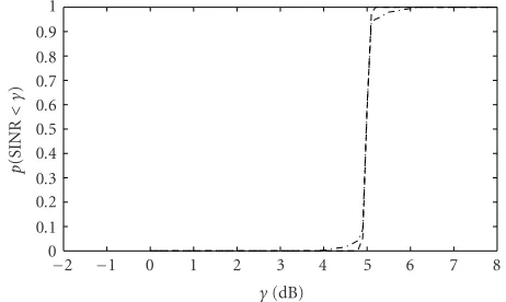
In Figures 4aand4b, the probability p(SINR < γ) of the receive SINR being less thanγis shown for the conven-tional power control method (15) versusγfor∆θ =1◦and
∆θ = 4◦, respectively. In this figure, the required SINR is γ◦ = 5 dB. As can be seen, for ∆θ = 4◦, more than 70%
Nonrobust power control combined with Method 1 Nonrobust power control combined with Method 2
(a)
Nonrobust power control combined with Method 1 Nonrobust power control combined with Method 2
(b)
Figure4: Probabilityp(SINR< γ) of the user received SINR being less thanγfor nonrobust power control method withγ◦=5 dB: (a) ∆θ=1◦; (b)∆θ=4◦.
and 68% of users have their receive SINRs less thanγ◦in the cases where Method 1 and Method 2 are used, respectively. In other words, the QoS constraints are not satisfied for the major part of users.
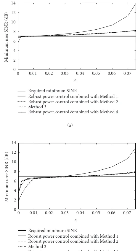
Figures 5a and 5b present the achieved minimal user SINRs versus ε for our robust power control method (32) in the cases ∆θ = 1◦ and ∆θ = 4◦, respectively. In this figure, we assume that the system-required SINR is γ◦ = 5 dB.
Figure 6is similar toFigure 5except for the fact that in
Figure 6the value of the system-required SINR isγ◦=7 dB.
0.08
Robust power control combined with Method 1 Robust power control combined with Method 2 Method 3
Robust power control combined with Method 4 (a)
Robust power control combined with Method 1 Robust power control combined with Method 2 Method 3
Robust power control combined with Method 4 (b)
Figure5: Minimum user received SINRs of the proposed robust power control technique and of Method 3 versusεforγ◦ =5 dB:
(a)∆θ=1◦; (b)∆θ=4◦.
the same for all the robust methods tested. This motivates the use of identical values of ε for all the robust methods used in simulations. Interestingly, the actual worst cases for
∆θ = 1◦ and∆θ = 4◦ correspond to the valuesε = 0.07 andε=0.28, respectively, which are substantially larger than the values ofεsufficient for providing good robustness (see Figures5and6). This can be explained by the fact that worst-case designs may be overly conservative (i.e., the actual worst case may occur very rarely) and, therefore, smaller values of robustness parameterεare sufficient to achieve satisfactory robustness.
Robust power control combined with Method 1 Robust power control combined with Method 2 Method 3
Robust power control combined with Method 4 (a)
Robust power control combined with Method 1 Robust power control combined with Method 2 Method 3
Robust power control combined with Method 4 (b)
Figure6: Minimum user received SINRs of the proposed robust power control technique and of Method 3 versusεforγ◦ =7 dB:
(a)∆θ=1◦; (b)∆θ=4◦.
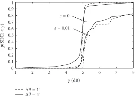
The probabilityp(SINR< γ) of the conventional and ro-bust power control techniques combined with Method 1 is shown inFigure 7versusγ. In this figure,γ◦=5 dB. For the sake of comparison of the nonrobust and robust power con-trol approaches, the valuesε=0 andε=0.01 are tested in this figure.
Figure 8 is similar to Figure 7 except for the fact that
beamforming Method 2 is used instead of Method 1.
Figure 9displays the probabilityp(SINR< γ) of Method
8
Figure7: Probability of the user received SINR being less thanγfor the robust and nonrobust power control methods combined with Method 1 versusγ.γ◦=5 dB.
Figure8: Probability of the user received SINR being less thanγfor the robust and nonrobust power control methods combined with Method 2 versusγ.γ◦=5 dB.
Figure 10is similar to Figure 7except for the fact that
beamforming Method 4 is used instead of Method 1. In Figures7–10, lower probability curves in the region γ ≤γ◦indicate improvements achieved by robust methods (withε >0) in comparison to the nonrobust techniques (that correspond toε=0). It can also be seen that the performance of our robust power control method combined with noncen-tralized beamforming Methods 1 and 4 is very similar to that of the robust beamforming algorithm of [12] (Method 3).
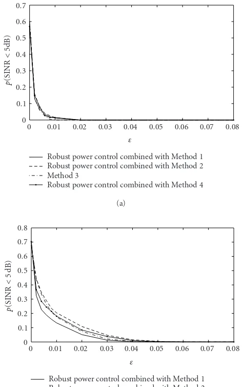
Figures 11aand11b display the probability p(SINR < 5 dB) as a function of εfor∆θ = 1◦ and∆θ = 4◦, respec-tively. As can be observed fromFigure 11, for∆θ =4◦, this probability drops from approximately 70% (for nonrobust methods withε=0) to less than 20% (when using our robust power control technique along with beamforming Methods 1, 2, and 4, as well as robust beamforming Method 3; all with ε=0.01).
To see how much transmitted power is required for
8
Figure9: Probability of the user received SINR being less thanγfor Method 3 versusγ.γ◦=5 dB.
Figure 10: Probability of the user received SINR being less than
γfor the robust and nonrobust power control methods combined with Method 4 versusγ.γ◦=5 dB.
the proposed robust power control method, the transmit-ted power per user is displayed in Figures12aand12bfor γ◦=5 dB andγ◦=7 dB, respectively, as a function ofε.
FromFigure 12, it can be seen that for a wide range of
0.08
Robust power control combined with Method 1 Robust power control combined with Method 2 Method 3
Robust power control combined with Method 4 (a)
Robust power control combined with Method 1 Robust power control combined with Method 2 Method 3
Robust power control combined with Method 4 (b)
Figure 11: Probability of the user received SINR being less than
γ◦=5 dB for the proposed robust power control technique and for
Method 3 versusε: (a)∆θ=1◦; (b)∆θ=4◦.
combined with Method 4 decreases when the parameterεis increased from zero to moderate values (e.g., toε=0.01).
Comparing the results of Figure 12 with those of
Figure 11, we can see that in the robust power control and
beamforming methods tested, quite substantial robustness improvements in terms of the percent of QoS-supported users can be achieved only at aslightincrease of the trans-mitted power.
5. CONCLUSIONS
A new centralized downlink power control algorithm is proposed for cellular wireless communication systems. Our technique provides a substantially improved robustness against imperfect knowledge of the wireless channel by
0.07
Robust power control combined with Method 1 Robust power control combined with Method 2 Method 3
Robust power control combined with Method 4 (a)
Robust power control combined with Method 1 Robust power control combined with Method 2 Method 3
Robust power control combined with Method 4 (b)
Figure 12: Required transmitted power for the proposed robust power control technique and for Method 3 versusε: (a)γ◦=5 dB;
(b)γ◦=7 dB.
means of maintaining the required QoS for the worst-case channel uncertainty.
Simulation results have validated a substantially im-proved robustness of our algorithm as compared to the con-ventional power control approach and demonstrated that such improvements are achieved at the price of only a slight increase of the total transmitted power.
APPENDIX
Proof ofLemma 1. SinceAandΛ=diag(λ1,. . .,λn) are uni-tarily similar, there exists a unitary matrixQsuch thatA=
QΛQH = ni=1λiqiqHi [22], whereqi is the ith column of Q. Here, we assume that|λ1| ≥ · · · ≥ |λn|. SinceQis an
n×n unitary matrix, anyn dimensional vector x can be expressed as x = ni=1αiqi, whereαi = qHi x. Accordingly,
and the lemma is proved.
It can be readily verified that (A.1) jointly become equal-ities if and only ifA=ξxxH, whereξis an arbitrary scalar.
ACKNOWLEDGMENTS
The authors gratefully acknowledge numerous helpful sug-gestions of the anonymous reviewers. In particular, one of our reviewers suggested using the robust modification (36) of the beamformer (35). This work was supported in part by the Natural Sciences and Engineering Research Coun-cil (NSERC) of Canada; Communications and Information Technology Ontario (CITO); Premier’s Research Excellence Award Program of the Ministry of Energy, Science, and Tech-nology (MEST) of Ontario; and the Wolfgang Paul Award Program of the Alexander von Humboldt Foundation.
REFERENCES
[1] S. Kandukuri and S. Boyd, “Optimal power control in
interference-limited fading wireless channels with outage-probability specifications,” IEEE Transactions on Wireless Communications, vol. 1, no. 1, pp. 46–55, 2002.
[2] G. J. Foschini and Z. Miljanic, “A simple distributed au-tonomous power control algorithm and its convergence,” IEEE Trans. Vehicular Technology, vol. 42, no. 4, pp. 641–646, 1993.
[3] A. F. Almutairi, S. L. Miller, H. A. Latchman, and T. F. Wong, “Power control algorithm for MMSE receiver based CDMA systems,” IEEE Communications Letters, vol. 4, no. 11, pp. 346–348, 2000.
[4] H. Boche and M. Schubert, “A new approach to power adjust-ment for spatial covariance based downlink beamforming,” inProc. IEEE International Conference Acoustics, Speech, and Signal Processing, vol. 5, pp. 2957–2960, Salt Lake City, Utah, USA, May 2001.
[5] S. A. Grandhi, R. Vijayan, D. J. Goodman, and J. Zander, “Centralized power control in cellular radio systems,” IEEE Trans. Vehicular Technology, vol. 42, no. 4, pp. 466–468, 1993. [6] D. Gerlach and A. Paulraj, “Base station transmitting antenna arrays for multipath environments,”Signal Processing, vol. 54, no. 1, pp. 59–73, 1996.
[7] C. Farsakh and J. A. Nossek, “Spatial covariance based
down-link beamforming in an SDMA mobile radio system,” IEEE
Trans. Communications, vol. 46, no. 11, pp. 1497–1506, 1998. [8] F. Rashid-Farrokhi, K. J. R. Liu, and L. Tassiulas, “Transmit beamforming and power control for cellular wireless systems,” IEEE Journal on Selected Areas in Communications, vol. 16, no. 8, pp. 1437–1450, 1998.
[9] M. Bengtsson and B. Ottersten, “Optimal and suboptimal transmit beamforming,” inHandbook of Antennas in Wireless Communications, L. C. Godara, Ed., CRC Press, Boca Raton, Fla, USA, August 2001.
[10] H. Boche and M. Schubert, “SIR balancing for multiuser
downlink beamforming—a convergence analysis,” inProc.
IEEE International Conference on Communications, vol. 2, pp. 841–845, New York, NY, USA, April–May 2002.
[11] G. Andrieux, J.-F. Diouris, and Y. Wang, “Channel time vari-ation effects on transmit beamforming in the TDD mode of UMTS,” inProc. IEEE International Symposium on Personal, Indoor and Mobile Radio Communications, vol. 5, pp. 1987– 1991, Lisboa, Portugal, September 2002.
[12] M. Bengtsson, “Robust and constrained downlink beamform-ing,” inProc. European Signal Processing Conference, pp. 1433– 1436, Tampere, Finland, September 2000.
[13] M. Schubert and H. Boche, “An efficient algorithm for op-timum joint downlink beamforming and power control,” in Proc. IEEE Vehicular Technology Conference, vol. 4, pp. 1911– 1915, Birmingham, Ala, USA, May 2002.
[14] A. Czylwik, “Downlink beamforming for mobile radio sys-tems with frequency division duplex,” inProc. IEEE Interna-tional Symposium on Personal, Indoor and Mobile Radio Com-munications, vol. 1, pp. 72–76, London, UK, September 2000. [15] M. Bengtsson, “Pragmatic multi-user spatial multiplexing with robustness to channel estimation errors,” inProc. IEEE International Conference on Acoustics, Speech, and Signal Pro-cessing, vol. 4, pp. 820–823, Hong Kong, April 2003.
[16] U. Madhow and M. L. Honig, “MMSE interference
sup-pression for direct-sequence spread-spectrum CDMA,”IEEE Trans. Communications, vol. 42, no. 12, pp. 3178–3188, 1994. [17] K. I. Pedersen, P. E. Mogensen, and B. H. Fleury, “Spatial channel characteristics in outdoor environments and their impact on BS antenna system performance,” inProc. IEEE Vehicular Technology Conference, vol. 2, pp. 719–723, Ottawa, Ontario, Canada, May 1998.
[18] K. I. Pedersen, P. E. Mogensen, and B. H. Fleury, “A stochas-tic model of the temporal and azimuthal dispersion seen at the base station in outdoor propagation environments,”IEEE Trans. Vehicular Technology, vol. 49, no. 2, pp. 437–447, 2000. [19] M. Biguesh, S. Shahbazpanahi, and A. B. Gershman, “Robust power adjustment for transmit beamforming in cellular com-munication systems,” inProc. IEEE International Conference on Acoustics, Speech, and Signal Processing, vol. 5, pp. 105–108, Hong Kong, April 2003.
[21] S. Valaee, B. Champagne, and P. Kabal, “Parametric localiza-tion of distributed sources,”IEEE Trans. Signal Processing, vol. 43, no. 9, pp. 2144–2153, 1995.
[22] H. L¨utkepohl,Handbook of Matrices, John Wiley & Sons, New York, NY, USA, 1996.
Mehrzad Bigueshwas born in Shiraz, Iran. He received the B.S. degree in electronics engineering from Shiraz University in 1991, and the M.S. and Ph.D. degrees in telecom-munications (with honors) from Sharif University of Technology (SUT), Tehran, Iran, in 1994 and 2000, respectively. During his Ph.D. studies, he was cooperating with Guilan University and SUT as a Lecturer. During the period from November 1998 to
August 1999, he was with INRS-T´el´ecommunications, Universit´e du Qu´ebec, Canada, as a Doctoral Trainee. From 1999 to 2001, he was with Iran Telecom Research Center (ITRC). During 2000– 2001, he was with Electronics Research Center, SUT, and also in touch with industry. Since March 2002, he has been a Postdoc-toral Fellow Researcher in the Communication Systems Depart-ment, University of Duisburg-Essen, Duisburg, Germany. His re-search interests include array signal processing, MIMO systems, wireless communications, power control, and radar systems.
Shahram Shahbazpanahi was born in Sanandaj, Kurdistan, Iran. He received his B.S., M.S., and Ph.D. degrees from Sharif University of Technology, Tehran, Iran, in 1992, 1994, and 2001, respectively, all in electrical engineering. From September 1994 to September 1996, he was a Faculty Member in the Department of Electrical Engineering, Razi University, Kermanshah, Iran. From July 2001 to March 2003, he
was conducting research as a Postdoctoral Fellow in the Depart-ment of Electrical and Computer Engineering, McMaster Univer-sity, Hamilton, Ontario. Since March 2003, he has been continuing his research as a Visiting Researcher in the Department of Com-munication Systems, University of Duisburg-Essen, Duisburg, Ger-many, while being affiliated with McMaster University as an Ad-junct Professor. His research interests include statistical and array signal processing, space-time adaptive processing, detection and estimation, smart antennas, spread spectrum techniques, MIMO communications, as well as DSP programming and hardware/real-time software design for telecommunication systems.
Alex B. Gershman received his Diploma and Ph.D. degrees in radiophysics from the Nizhny Novgorod University, Russia, in 1984 and 1990, respectively. From 1984 to 1997, he held research positions at several research institutes in Russia. From 1997 to 1999, he was a Research Associate in the Department of Electrical Engineering, Ruhr University, Bochum, Germany. In 1999, he joined the Department of Electrical and
Computer Engineering, McMaster University, Hamilton, Ontario, Canada, where he is now a Professor. He also held visiting po-sitions at the Swiss Federal Institute of Technology, Lausanne, Ruhr University, Bochum, and University of Duisburg-Essen, Duis-burg. His main research interests are in statistical and array signal