R E S E A R C H
Open Access
Successive interference cancelation and MAP
decoding for mobile MIMO OFDM systems and
their convergence behavior
Vamadevan Namboodiri
3*, Hong Liu
2and Predrag Spasojevi´c
1Abstract
Turbo equalization schemes based on minimum mean square error criteria available in the literature for multiple-input multiple-output (MIMO) systems are computationally expensive, as they require a relatively large matrix inversion. In this article, we propose a suboptimal, successive interference cancelation (SIC)-based maximum a posteriori (MAP) decoding in doubly dispersive channels for orthogonal frequency division multiplexing (OFDM) MIMO systems (SIC-MAP-MIMO). SIC-MAP-MIMO leverages on the soft feedback symbol estimate to remove the intercarrier
interference and coantenna interference from the received data thus making the subsequent MAP decoding simple. Extrinsic information transfer chart analysis supplemented with numerical simulation results show that SIC-MAP-MIMO achieves comparable BER performance to similar equalization schemes but with significant computational savings.
Introduction
Wireless communication based on MIMO systems has gained popularity due to the potential capacity increases it can provide [1]. OFDM has been a popular tech-nique for transmission of signals over wireless channels primarily because the receiver design is relatively sim-ple, as it does not require a complex equalizer. MIMO-OFDM-based transmission systems can thus provide very high data rates with a relatively simple receiver design and are adopted in many recent wireless communica-tion standards. Examples include (a) IEEE-802.11-n/ac [2,3], (b) IEEE 802.16e/m (WiMAX) [4], and (c) LTE [5]. IEEE-802.11-n [2] specifies a maximum of 600 Mb/s using four independent spatial streams transmitted over a 40-MHz channel. IEEE-802.11-ac [3] specifies a data rate of up to 3.5 Gb/s using eight independent spatial streams in an 80-MHz channel. WiMAX [4] specifies a limit of approximately 100 Mb/s using four spatial streams in a 5-MHz channel. LTE suggests a peak data rate of 326.4 Mb/s using a 20-MHz downlink with four transmit antennas [5]. Under static multipath channel conditions, the received signal in the MIMO receiver is corrupted only by coantenna interference (CAI). However,
*Correspondence: [email protected] 3Broadcom Corporation, Bangalore, India
Full list of author information is available at the end of the article
high transceiver mobility at high carrier frequency causes severe time-varying frequency-selective multipath fading at the receiver. This breaks the orthogonality of subcar-riers and hence causes intercarrier interference (ICI) in the received signal. As an example, at a transmission frequency of 5 GHz and at vehicular speeds of 240– 480 km/h, which are common in high-speed trains, the expected maximum receiver Doppler spread in WiMAX and LTE systems is of the order of 12 to 23% of the intercarrier spacing. Furthermore, it is believed that future wireless communications will adopt higher car-rier frequencies and higher mobility requirements, fur-ther increasing the maximum relative Doppler frequency and exacerbating the ICI. In such scenarios, as discussed in this article, the efficient detector design for MIMO-OFDM systems is a challenging practical problem.
Some early equalization schemes proposed in the liter-ature to cope with ICI and CAI are (a) block linear [6], (b) banded minimum mean square error (MMSE) linear [7], and (c) banded MMSE decision-feedback [8]. More recently, various iterative equalization schemes based on successive cancelation of ICI and CAI [9-13] or turbo principle [9,14-16] were proposed. A brief survey of the iterative equalization schemes published in the last decade and how they differ from the proposed scheme is given in the sequel. In general, turbo-like iterative schemes are
found to have superior performance compared to others, but they usually suffer from high computation complexity, albeit at varying degrees, and thus require high silicon area for implementation and high battery power for opera-tion. Such practical application challenges have motivated us to propose a new low-complexity detector scheme for OFDM-MIMO with an improved trade-off between per-formance and implementation complexity in [17] and in this study.
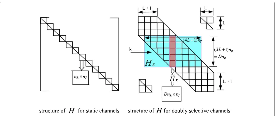
The iterative/successive interference cancelation scheme proposed in Section “SIC-based MAP receiver: MIMO (SIC-MAP-MIMO)” is related to, yet distinct from, a number of published algorithms. In [9], multiple access interference (MAI) and inter-symbol interference (ISI) in a static multipath environment are removed in a code-division-multipath-access (CDMA) system using a combination of soft-interference cancelation and linear MMSE filtering. [10] is an extension of the scheme pro-posed in [9], but in [10], additional filtering is performed to suppress both the ISI and MAI residuals. Turbo Equal-ization (TE) proposed in [18] performs MMSE-based turbo estimation of the transmitted symbol on single-carrier systems under static channel conditions, followed by LLR computation and BCJR decoding. This involves matrix inversion for the estimation of every symbol per iteration and is thus computationally expensive (O(N2) operations). Additional complexity reduction for TE is achieved in doubly selective OFDM systems by working on a submatrix around the system matrix as in [19]. SIC-MAP-MIMO is perhaps close to the ISI cancelation stage of [9]. However, unlike [9,10], SIC-MAP-MIMO requires only O(N) operations. It leverages the banded sparse structure of the single-user LTV MIMO system matrix, where the significant channel coefficients are concen-trated in a banded structure along the diagonal [6,8,19] as shown in Figure 1 (right). There are a number of SIC schemes which try to diagonalize the system matrix. In [11], an iterative decision feedback equalizer is proposed to perform ICI cancelation such that the modified system matrix becomes diagonal and, consequently, the equal-izer becomes single-tap. In [20], ICI is removed from the time domain signal (resulting in a diagonal frequency domain system matrix) and is converted to frequency domain. Hard decisions are made on the equalized signal, following which it is converted back to time domain and the time-frequency iterations are repeated. In [12], the mean value of the transmit symbol is computed using the LLR values from the decoder. This is used to remove the ICI from the received symbol, resulting in a diago-nal system matrix. A modified low-complexity MMSE equalizer that takes the decision error into account is now derived. In [13], a turbo-EM receiver is proposed. Here, the system matrix is estimated from the EM detector, whereas transmit symbols are estimated either using the
EM algorithm or from the LLR values from the decoder. Using these estimates, ICI is computed and removed as in [11,12] to obtain a diagonal system matrix. The scheme in [21] is applicable to single-carrier (SC) systems. Here, the received signal is split into small segments, such that the channel remains approximately static during each small segment. Suitable signal processing is performed on each of these segments such that the resulting chan-nel matrix is made diagonal. TE, like the one described in [18], is performed on the modified system to recover the received bits. The above-described schemes try to obtain a modified system with only diagonal entries, such that a single tap equalizer can equalize the modified system. Unlike this, in SIC-MAP-MIMO, copies of the received signal on the same and adjacent subcarriers of all receive antennas are carefully separated out to obtain frequency diversity. The resulting system matrix is a col-umn matrix. It has been identified through simulations that the banded sparse structure of the system matrix, as in the case of doubly selective MIMO channels, allows this simplification without sacrificing performance. MAP decoding is performed on this simplified system. The scheme proposed in [15] is similar to [19], but is extended to OFDM MIMO. It proposes a new window for received signal. SIC-MAP-MIMO does not perform windowing, but better performance can be expected with any of the windowing proposed above.
Figure 1OFDM channel structure.
This article is organized as follows: Notations used in this article are explained first. In the next section, the system model is presented, followed by a description of SIC-MAP-MIMO in Section “SIC-based MAP receiver: MIMO (SIC-MAP-MIMO)”. In Section “Computational complexity analysis”, we compare the computation com-plexity of SIC-MAP-MIMO with similar equalization schemes. In Section “Numerical results”, the numeri-cal results are presented. The article concludes with “Conclusion ’’ section, where we draw final conclusions.
Notation: (·)tdenotes transpose;(·)H denotes conjugate transpose (Hermitian); ⊗is the Kronecker product;{a}
denotes a set with elements{a(0),a(1),. . .};Ffor normal-ized N point Discrete Fourier Transform (DFT), where
Fk,l := (1/
√
N)e−j2πkl/N; Iis the identity matrix; ik is the kth column of I; 0nR×nT is the null matrix of size
nR×nT;∗denotes convolution;|| · ||forl2-norm;·is the ceiling of a function; modulo-N is denoted by ·N;
Re(·)andIm(·)for the real and imaginary parts, respec-tively. diag(νx) is the diagonal matrix with vector νx in
the main diagonal. Expectation is denoted byE{·}. Both
× and · are used to denote multiplication. Bold lower-case letters (e.g.,x) denote vectors, and bold uppercase letters (e.g.,X) denote matrices. Covariance is denoted by cov(b,c):=E{bcH} −E{b}E{cH}.
System model
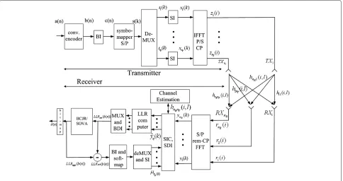
The MIMO OFDM transceiver system withnT transmit and nR receive antennas used in this article is given in Figure 2. We assume thatnT ≤nR. Information bits({a}) are convolutionally encoded ({b}) and passed through a bit interleaver({c}). The symbol mapper modulates them
into QAM symbols ({s}). A set of N of these coded QAM “frequency domain” symbols is collected to form an OFDM symbol. The demultiplexer collectsnT OFDM symbols (an OFDM symbol frame) and sends each symbol ({sq})to one of thenT transmit paths. The symbol inter-leaver (SI) in each path interleaves them({xq}). They are then converted into “discrete time-domain” samples({zq}) by performing anN- point IDFT. A cyclic prefix (CP) of lengthNp≤Nis added to each of these symbols. They are then simultaneously transmitted fromnT transmit anten-nas. Transmit and receive antennas are assumed to be placed sufficiently far apart among themselves so that the
nT·nRmultipath channels are independent. Furthermore, these channels are assumed to be both frequency- and time-selective and are modeled as a linear time-varying (LTV) system with a discrete impulse response hpq(i,l) that is defined as the timeiresponse to an impulse at time
i−lfor the wireless channel from theqth transmit antenna to thepth receive antenna. Static multipath channel con-ditions are treated as a special case of the above general formulation. At the receiver, the CP-removed OFDM data from each receive antenna are converted back to the “fre-quency domain” by performingN-point DFT and passed to the SIC and Symbol Deinterleaver. The log likelihood ratio (LLR) computer computes the LLRs of the received bits from the interference removed observation. This is appropriately multiplexed, bit-deinterleaved, and passed to a BCJR- or SOVA-based decoder.
We assume perfect carrier, symbol, and sample synchro-nization at the receiver. Besides, it is assumed that the channel is known at the receiver. We follow the modeling used in [6]. Assuming that maximum channel delay spread
Figure 2MIMO OFDM transceiver.
rp(i)= q=nT
q=1 l=Nh−1
l=0
hpq(i,l)zq(i−l)+np(i), 0≤i<N,
(1)
where{np(i)}are additive white Gaussian noise (AWGN) samples on thepth receive antenna with zero mean and varianceσ2(we assume equal noise power on all receive antennas). The conditionNh≤Npensures thatrp(i) con-tains contributions only from the currently transmitted OFDM symbol frame. The received vector at theith time instant,r(i) :=[r1(i),r2(i),. . .,rnR(i)]t, can be expressed as
r(i)= l=Nh−1
l=0
H(i,l)z(i−l)+n(i), 0≤i<N, (2)
where
H(i,l):=
⎡ ⎢ ⎢ ⎢ ⎣
h11(i,l) h12(i,l) . . . h1nT(i,l)
h21(i,l) h22(i,l) . . . h2nT(i,l)
. . . . . . . . . . . .
hnR1(i,l) hnR2(i,l) . . . hnRnT(i,l)
⎤ ⎥ ⎥ ⎥ ⎦,
z(i):=[z1(i),z2(i),. . .,znT(i)]t and n(i):=[n1(i),n2(i), . . .,nnR(i)]t. Over a time window of N sample duration, (2) can be expressed in matrix form as
r=z+ψ, (3)
wherer:=[rt(0),rt(1),. . .,rt(N−1)]t∈CN·nR,z:=[zt(0),
zt(1),. . .,zt(N−1)]t∈ CN·nT,ψ :=[nt(0),nt(1),. . .,nt
(N−1)]t∈CN·nRand∈CN·nR×N·nTis the time varying system matrix given in (4).
:= ⎡ ⎢ ⎢ ⎢ ⎣
H(0, 0)0nR×nT . . . H(0,Nh−1) . . . H(0, 1) H(1, 1)H(1, 0) 0nR×nT . . . . . . H(1, 2) . . . . . . . . . . . . . . . . . .
0nR×nT . . . H(N−1,Nh−1) . . . . . . H(N−1, 0) ⎤ ⎥ ⎥ ⎥ ⎦
(4)
Nsamples from the same OFDM symbol fromnRreceive antennas (a total ofN·nRsamples) are grouped together and presented to a DFT processor which, in turn, outputs
N·nR“frequency domain” samples. This operation can be represented mathematically as follows:
y = Q(Rx)r=Q(Rx)z+Q(Rx)ψ = Q(Rx)Q(Tx)Hx+w
= Hx+w, (5)
whereQ(Tx)=F⊗InT,Q
(Rx)=F⊗I
nR,H=Q
(Rx)Q(Tx)H,
z = Q(Tx)Hx,y :=[yt(0),yt(1),. . .,yt(N−1)]t,y(k) := [y1(k),y2(k),. . .,ynR(k)]t, x :=[xt(0),xt(1),. . .,xt(N − 1)]t,x(k) :=[x
1(k),x2(k),. . .,xnT(k)]t andw = Q (Rx)ψ.
Note that (a) each element ofHcan be written as,
Hpq(m,n) = 1
N
l=Nh−1
l=0 i=N−1
i=0
×hpq(i,l)e−j2π(m−n)i/Ne−j2πln/N (6)
The total transmit power is assumed to be unity with all antennas transmitting equal power. Multipath time-varying channel coefficients are modeled as zero mean complex Gaussian random variables. Fading coefficients for different paths are assumed to be statistically inde-pendent while the coefficient for a given path is time-correlated with the autocorrelation function (wide-sense stationary uncorrelated scattering model) given by [24],
E{h(m,l)h(n,l)∗} =αlJ0(2π(m−n)fdTs) (7)
where αl is the average power of the lth path,J0(·) is the zeroth-order Bessel function of the first kind, Ts is the sampling interval, and fd is the maximum Doppler frequency given by
fd=
v
cfccos(θd). (8)
Herevis the vehicle speed,cis the velocity of light,fcis the carrier frequency, andθdis the scattering angle.
It has been shown that H will be a block-banded matrix with significant block coefficients concentrated in a banded structure, with width Dalong the diagonal [6,8,19].Dis a design parameter typically chosen asD=
2L+ 1, whereL = fdTsNin which N is the OFDM symbol length. If the channel is static,will be a block cir-culant matrix andHwill be a block diagonal matrix. Dif-ferent structures ofHare shown in Figure 1. Interference from adjacent subcarriers gives raise to ICI. The received signal on each subcarrier at each receiver antenna con-tains contributions from all transmit antennas. This gives rise to CAI [6].
SIC-based MAP receiver: MIMO (SIC-MAP-MIMO) Formulation of the proposed MAP receiver
In this section, we present a low-complexity iterative receiver that implements SIC, followed by MAP decoding for MIMO systems. The proposed scheme first modifies the system matrix to a single column matrix by selectively removing the ICI and CAI interference from the received symbols, where ICI and CAI interference are computed using the feedback symbol mean values. Soft information can be computed directly with low cost from this modified model. These are fed to a MAP bit decoder. The following observations are key in formulating the proposed scheme:
1. The relative magnitude of each subblock and superblock diagonal element of the doubly selective Rayleigh fading channel matrixHdecreases significantly as we move away from the main diagonal. This has been justified in [19,22]. We can
thus ignore all elements that are far away from the main diagonal without significantly impacting performance. This is further justified through simulations in the “Numerical results” section. Note that these elements are absent for a static multipath channel.
2. As theextrinsic information becomes more accurate over multiple turbo iterations, the conditional mean, μx(k) → x(k), which is the true symbol value and the conditional variance,νx(k) → 0nT×1.
Therefore, in each new iteration we can useμx(k)
from the previous iteration to selectively remove CAI and ICI from the received symbol in such a manner that the resulting system matrix is turned into a column matrix. MAP decoding of the modified system is computationally efficient to implement.
Based on observation 1, (5) can be approximated as
yk := [y(k−LN),. . .,y(k+LN)]t (9)
= Hkxk+wk,
where xk :=[x(k−2LN),. . .,x(k+2LN)]t, wk :=
[w(k−LN),. . .,w(k+LN)]t, and Hk is the shaded
(green) section of H in Figure 1 (right) given by (10). Note that modulo-N(N)operation is used in the above equation, thanks to the CP in the system.
Hk:=
For simplicity of notation, the modulo operation (N) is omitted in the sequel. Now,xk =μxk+δxk, whereδxkis the residual error, which approaches04L+1as the extrinsic LLR becomes more reliable over multiple iterations. Sub-stituting forxkin (9) and rearranging yields (12),w˜k, the
new noise, contains the ICI from the residual errorδxk. ˜
yk=Hk[i2L·nT,. . .,i(2L+1)·nT−1]x(k)+Hk
shown in red in Figure 1 (right). It is a matrix of size
D·nR×nT. For static channels whereL=0,y˜kwill only
havenR non-zero elements at the center (Figure 1, left). While dealing with the reception ofxq(k), thekth sym-bol from theqth transmit antenna,kth symbols from all other transmit antennas({xl(k)l=q}) are causing CAI on the received samplesyk. Using similar techniques to those
given above, the CAI can be estimated and removed from the system as well. The resulting system equation is
yqk=hqkxq(k)+w Section “Numerical results”, the combined contributions of residual ICI and CAI to the noise varianceσ2are small and decreasing over multiple iterations as the reliability in the feedback information increases. We thus approximate σ2InR(2L+1)≈σ2InR(2L+1).
The LLR computer calculatesLLRext(cq(n)), the
extrin-sic LLR. It represents information about cq(n) con-tained in yqk and P(cq(l)) for all l=n. These are passed to a MAP decoder where they are used as a priori LLRs. LLRext(cq(n)) is calculated from the mod-ified system using (15), where 0≤i≤Q−1,S=[m0,
m1,. . .,mQ−1]t∈F2,{η} =map(S)is the signal constel-lation andF2is binary Galois Field.Qdenotes the number
of bits per symbol. For example,Q= 1 for BPSK,Q= 2
As shown in the Appendix, for QPSK, the above expres-sion can be simplified as
LLRext(cq(2k)) =
A closer look at the derivation reveals that this expres-sion is applicable, within a scale factor, to any constant-modulus constellations. Observe that theextrinsic LLRof
cq(n)is conditioned only onyqk, andy
qkdepends only on the present symbolxq(k). This makes the evaluation of
LLRext(cq(n))easy.
Receiver operation
The SIC-MAP-MIMO system block diagram is shown in Figure 2. Elements of Hk are obtained from the
chan-nel estimation block [25-29]. BCJR-(Bahl, Cocke, Jelinek and Raviv) or SOVA (Soft Output Viterbi Algorithm) [30]-based decoders compute LLRapp(b(n))—the a pos-teriori reliability infotextation of each coded bit—in the LLR fotext. The input a priori LLR to the decoder is subtracted from LLRapp(b(n))to obtain theextrinsic reli-ability infotextation LLRext(b(n)). It is passed through a bit interleaver and is used in the soft-mapper to com-pute mean μs. This is demultiplexed appropriately to
obtainμs1,μ
s2,. . .,μ
to produceμx1,μx2,. . .,μx
nT which, in turn, are used in SIC-MAP-MIMO to remove the ICI and CAI interference as described in (13) and (14). The ICI- and CAI-removed data are fed to the LLR computer to generate more reli-able LLRs to further improve the output bit estimate. This process is repeated until further gains are insignificant. LLRapp(b(n))are then hard-sliced at the bit-map block and infotextation bit estimates aˆ(n) are retrieved from the received data bit estimatesbˆ(n). Mapping LLRext(b(n))s to
Computation of residual ICI and CAI
Neglecting the tetexts in H that are beyond the band (shaded area in Figure 1), the interference-canceled signal,
yp(k), at thelth iteration can be represented as
In (20), the first tetext is the desired signal while the sec-ond and third tetexts are the ICI and CAI, respectively. Average power of ICI,PpkICI, at thekth subcarrier on the
pth receive antenna can be expressed as,
PpkICI =
2 is the conditional
vari-ance at the(l−1)th iteration, νlq−1(k), is given in (19). Average ICI power on the pth receive antenna, there-fore, is obtained by averagingPICIpk acrossk, i.e., PpICI =
carrier on thepth receive antenna,PpkCAI, can similarly be written as,
As earlier, average CAI power,PCAIp , on thepth receive antenna is obtained by averaging PCAIpk across k. The signal-to-interference ratio (SIR) at the kth subcarrier afterliterations can be computed as,
SIR= E(Hp,q(k,k)xq(k) 2)
PpICI+PpCAI (23)
Computational complexity analysis
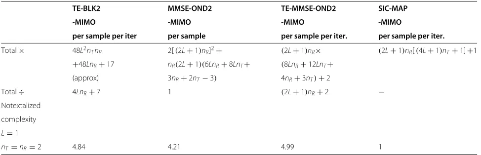
In this section, the computational complexity of SIC-MAP-MIMO is compared with two iterative equalization schemes [19,22]. The perfotextance of these schemes is contrasted in Section “Numerical results”. The authors of [19,22] have been identified for comparison purposes, since they have a few aspects common to the proposed scheme, such as all the three schemes (a) leverage on the banded nature of the system matrix, (b) leverage on the feedback LLR infotextation, and (c) propose low-complexity symbol estimation for doubly selective OFDM systems.
Among a group of three proposed equalizers in [22], the second equalizer is the best perfotexter. We refer the equalizers in [19] as MMSE-OND2-MIMO and in [22] as TE-BLK2-MIMO (second class of equalizers). We incorporate channel coding to render a fair comparison. These schemes were originally proposed for SISO chan-nels. In this study, we have extended the above schemes to MIMO systems. TE-BLK2-MIMO is a low-complexity block TE scheme. TE-MMSE-OND2-MIMO is a serial TE scheme based on a section of H(Hk in the right of
Table 1 Complexity comparison
TE-BLK2 MMSE-OND2 TE-MMSE-OND2 SIC-MAP
-MIMO -MIMO -MIMO -MIMO
per sample per iter per sample per sample per iter. per sample per iter.
Total× 48L2n
TnR 2[(2L+1)nR]2+ (2L+1)nR× (2L+1)nR[(4L+1)nT+1]+1
+48LnR+17 nR(2L+1)(6LnR+8LnT+ (8LnR+12LnT+
(approx) 3nR+2nT−3) 4nR+3nT)+2
Total÷ 4LnR+7 1 (2L+1)nR+2 −
Notextalized
complexity
L=1
nT=nR=2 4.84 4.21 4.99 1
lookup table. These operations are, therefore, not consid-ered in the comparison (although not differentiated here, the cost of a divider, in practice, is higher than that of a multiplier.)
For a typical set of parameters, it is clear from Table 1 that TE-BLK2-MIMO and TE-MMSE-OND2-MIMO require approximately five times more com-putations than SIC-MAP-MIMO per iteration. A fair evaluation of the computational complexity can be under-taken only after studying their convergence behavior in the next section. The non-iterative MMSE scheme, MMSE-OND2-MIMO, requires four times more compu-tations per iteration than SIC-MAP-MIMO.
Numerical results
We consider WiMAX-like transmission at different vehic-ular speeds at a transmission frequency of 5 GHz over a vehicular-A channel [32], which is the customary channel model for WiMAX and LTE systems. We thus choose an OFDM-MIMO system withN =256,Nh=6,Np=N/8, andnT =nR=2. The transmission bandwidth is 5 MHz. Speeds considered are 3, 120, 240, 360, and 480 km/h, which corresponds to notextalized Doppler frequencies of 0.07, 5.8, 11.7, 17.6, and 23.3%, respectively. Results are shown for a rate 1/2 convolutional code having the gener-ator polynomial(7, 5). Symbols are QPSK modulated with average power = 1/nT. Both time and frequency interleav-ing are perfotexted with S-random interleavers [33], with
S = 31 andS = 7, respectively. ThenT·nRchannels are independent and Rayleigh fading, characterized by Jakes’ Doppler spectrum [24] with an exponentially decaying power delay profile. Simulations are run approximately for 107bits.
Figure 3 shows the average residual ICI and CAI inter-ference in SIC-MAP-MIMO at different vehicular speeds over multiple iterations. This gives good insight into the proposed algorithm. At iteration one, there is no ICI or CAI cancellation, and the graph therefore represents the
relative ICI and CAI powers in the uncompensated sys-tem. CAI is a bigger source of interference than ICI, even at very high vehicular speeds. It significantly dominates the AWGN level in the system at moderate to high SNRs (AWGN at 12 dB is shown in the figure). At high vehic-ular speeds, the ICI interference becomes significant if left uncompensated for. At each iteration, both CAI and ICI reduces by several dBs. After about six iterations, the CAI and ICI interference has been reduced so much that it is well below the AWGN level in the system, neglect-ing which, as is described in Section “Formulation of the proposed MAP receiver”, is a valid approximation at all practical vehicular speeds. The approximation in (13) and the proposed decoding scheme in general may not be valid for a generic system matrix Hk. As shown in
Figure 3, the banded sparse structure of the system matrix reduces the residual ICI and CAI interference upon mul-tiple iterations. That is the principal reason this simplifi-cation works. Note also that as we increase the vehicular speed, the proposed scheme is more effective in canceling the interference. This is because of the higher frequency diversity in the system due to Doppler spread.
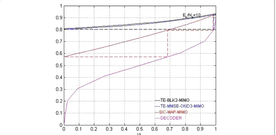
Convergence behavior of iterative systems is difficult to analyze in general. However, a simulation-based tech-nique called EXIT charts proposed in [23] has been found to be effective in evaluating the convergence behavior of iterative systems. The details of this fotextulation can be found in [34-36]. Detection schemes that may have low computational complexity per iteration might take more iterations to converge and vice-versa. This means that comparing the complexity per iteration for different schemes is not fair unless the convergence speed is also taken into account. EXIT charts are used in this section to investigate the convergence behavior of the iterative schemes.
Figure 3ICI power for 802.16 channel before and after the cancelation.
notextalized Doppler, are plotted forEb/N0=10 dB. The decoder EXIT chart is also shown in the same figure. The EXIT curve for MMSE-OND2-MIMO and BLK2-MIMO is quite close, but the exit curve for TE-BLK2-MIMO is consistently above the fotexter, showing the slight perfotextance superiority of TE-BLK2-MIMO. Although the SIC-MAP-MIMO EXIT chart starts at a
lower point, it has a higher slope and ends up very close to that of the other two. Such behavior is found to be true for different values ofEb/N0(data not shown). This is because the overall noise in the SIC-MAP-MIMO system during the initial iterations is higher than that of MMSE-OND2-MIMO, owing to ICI and CAI contributions from the residual error tetexts. However, as the estimator becomes
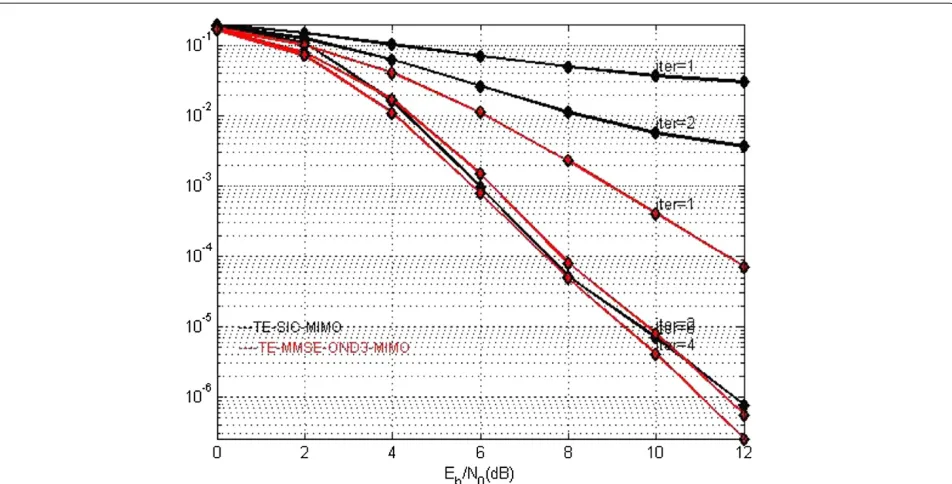
Figure 5BER versusEb/N0for different # iterations for SIC-MAP-MIMO (# iter 3, 6) and TE-MMSE-OND2-MIMO (# iter 1, 2) and
TE-BLK2-MIMO (# iter 1, 2) (nT=2,nR=2,N=256,Nh=6,fdTsN=0.12, QPSK).
more accurate with multiple iterations, these tetexts and, in turn, the system noise, gradually come down, as seen in Figure 3. All three schemes have very close endpoints corresponding toIA = 1, indicating identical asymptotic behavior of these schemes. The higher the EXIT curve slope, the better the BER gain per iteration. BER gain per iteration is, thus, higher for SIC-MAP-MIMO. It is clear
from Figure 4 that SIC-MAP-MIMO needs more number of iterations compared to the other two schemes for the same level of convergence.
The above inferences from the EXIT charts have been verified using simulations. Figure 5 depicts the BER perfotextance of these three iterative schemes for dif-ferent numbers of iterations for identical set up (12%
Table 2 QPSK alphabet
notextalized Doppler frequency). It can be observed that SIC-MAP-MIMO requires three iterations for the same level of convergence per iteration of the other two schemes. From these observations and from Table 1, it can be said that TE-MMSE-OND2-MIMO, TE-BLK2-MIMO, and MMSE-OND2-MIMO are, respectively, 66, 61, and 40% more expensive than the proposed algo-rithm. Figure 6 shows the final BER perfotextance of all three iterative schemes considered in our study for 23% notextalized Doppler frequency after six iterations. SIC-MAP-MIMO and TE-MMSE-OND2-MIMO have approximately the samesteady-stateperfotextance at high SNRs, whereas TE-BLK2-MIMO perfotexts slightly better than the other two.
Conclusion
We have proposed a low-complexity iterative channel equalization scheme, SIC-MAP-MIMO, based on the principle of SIC for OFDM-MIMO single-user systems. We demonstrated that SIC-MAP-MIMO perfotextance under time-varying multipath conditions is mostly on par with the two MMSE-based turbo equalization schemes: TE-MMSE-OND2-MIMO, which is based on a banded submatrix of the system matrix, and the block turbo equalization scheme, TE-BLK2-MIMO, which is based on the banded full system matrix. It was also found that TE-OND2-MIMO, TE-BLK2-MIMO, and MMSE-OND2-MIMO are, respectively, 66, 61, and 40% more expensive than the proposed algorithm. It was demon-strated that SIC-MAP-MIMO perfotextance progressively improves as the channel-time variation increases due to the increasing frequency diversity gain that TE-SIC-MIMO is taking advantage of. Another distinct advantage of the proposed algorithm is its high scalability (power versus perfotextance) in practical receivers.
Appendix
Derivation of Equation 16
Referring to Table 2 for the QPSK symbol alphabet definition. removing the common tetexts, we get
LLRext(cq(2k))
The authors declare that they have no competing interests.
Author details
1WINLAB, Rutgers University, North Brunswick, NJ, USA.2Broadcom
Corporation, Irvine, CA, USA.3Broadcom Corporation, Bangalore, India.
Received: 17 January 2012 Accepted: 19 July 2012 Published: 12 October 2012
References
1. GJ Foschini, Layered space-time architecture for wireless communication in a fading environment when using multi-element antennas. Bell Labs Technol. J .1(2), pp. 41–59 (1996)
2. IEEE, “IEEE P802.11n/D10.0,” (May 2009) 3. IEEE,“IEEE P802.11ac,”(May 2011)
4. IEEE, “IEEE standard for local and metropolitan area networks part 16. std. IEEE802.16E-2005, 2005,” (2005)
5. D Ast´ely, E Dahlman, P Frenger, R Ludwig, M Meyer, S Parkvall, P Skilletextark, N Wiberg, A future radio-access framework. IEEE J. Sel. Areas Commun.24(3), pp. 693–706 (2006)
6. A Stamoulis, SN Diggavi, N Al-Dhahir, Intercarrier interference in MIMO OFDM. IEEE Trans. Signal Process.50(10), pp. 2451–2464 (2002) 7. S Lu, B Narasimhan, N Al-Dhahir, A novel SFBC-OFDM scheme for doubly
selective channels. IEEE Trans. Veh. Technol.58(5), pp. 2573–2578 (2009) 8. L Rugini, Banelli, Banded equalizers for MIMO-OFDM in fast time-varying channels, inEUSIPCO 2006, Florence, Italy,9, (2), 18–48 September 2006) 9. X Wang, HV Poor, Iterative (turbo) soft interference cancelation and
10. T Abe, T Matsumoto, Space-time turbo equalization in frequency-selective MIMO channels. IEEE Trans. Veh. Technol.52(3), pp. 469–475 (2003) 11. S Tomasin, A Gorokhov, H Yang, J-P Linnartz, Iterative interference
cancelation channel estimation for mobile OFDM. IEEE Trans. Wirel. Commun.4(1), pp. 238–245 (2005)
12. SU Hwang, JH Lee, J Seo, Low-complexity iterative ICI cancelation equalization for OFDM systems over doubly selective channels. IEEE Trans. Broadcast.55(1), pp. 132–139 (2009)
13. M-L Ku, W-C Chen, C-C Huang, EM-based iterative receivers for OFDM and BICM/OFDM systems in doubly selective channels. IEEE Trans. Wirel. Commun.10(5), pp. 1405–1415 (2011)
14. M T ¨uchler, A Singer, R Kotter, Minimum mean squared error (MMSE) equalization using a priori infotextation. IEEE Trans. Signal Process.50, pp. 673–683 (2002)
15. L Rugini, P Banelli, K Fang, G Leus, Enhanced turbo MMSE equalization for MIMO-OFDM over rapidly time-varying frequency-selective channels, in IEEE 10th Workshop on Signal Processing Advances in Wireless
Communications, (2009 ), pp. 36–40
16. S Ahmed, T Ratnarajah, M Sellathurai, CFN Cowan, Iterative receivers for MIMO-OFDM and their convergence behavior. IEEE Trans. Veh. Technol. 58(1), pp. 461–468 (2009)
17. V Namboodiri, H Liu, P Spasojevi´c, Successive interference cancelation-based turbo equalization for MIMO OFDM systems, inProc. Conference on Infotextation Sciences and Systems, (Baltimore, MD, March 2011) 18. M T ¨uchler, R Kotter, A Singer, Turbo equalization: principles and new
results. IEEE Trans. Commun.50, pp. 754–767 (2002)
19. P Schniter, Low-complexity equalization of OFDM in doubly selective channels. IEEE Trans. Signal Process.52(4), pp. 1002–1011 (2004) 20. S Chen, T Yao, Intercarrier interference suppression and channel
estimation for OFDM systems in time-varying frequency selective fading channels. IEEE Trans. Consum. Electron.50(2), pp. 429–435 (2004) 21. QGL Ping, D Huang, A low complexity iterative channel estimation and
detection technique for doubly selective channels. IEEE Trans. Wirel. Commun.8(1), pp. 4340–4349 (2009)
22. K Fang, L Rugini, G Leus, Low-complexity block turbo equalization for OFDM systems in time-varying channels. IEEE Trans. Signal Process.56, pp. 5555–5566 (2008)
23. S ten Brink, Convergence behavior of iteratively decoded parallel concatenated codes. IEEE Trans. Commun.49(10), pp. 1727–1737 (2001) 24. WC Jakes,Microwave Mobile Communications(Wiley, New York, 1974) 25. MK Ozdemir, H Arslan, Channel estimation for wireless OFDM systems.
IEEE Commun. Surveys and Tutorials.9(2), pp. 18–48 (2007)
26. Y Mostofi, DC Cox, I C I mitigation for pilot-aided OFDM mobile systems. IEEE Trans. Wirel. Commun.4(2), pp. 765–774 (2005)
27. M Zhao, Z Shi, MC Reed, Iterative turbo channel estimation for OFDM system over rapid dispersive fading channel, inIEEE International Conference on Communications, (June 2007). pp. 4849–4854
28. WG Song, JT Lim, Channel estimation signal detection for MIMO-OFDM with time-varying channels. IEEE Commun. Lett.10, pp. 540–542 (2006) 29. Y Sun, M Yee, M Sandell, Iterative channel estimation with MIMO MMSE
-Turbo equalization, inVehicular Technology Conference, vol. 2, (Fall, 2003) 30. S Lin, DJ Costello,Error Control Coding(Prentice Hall, NJ, 2004) 31. L Hong,Frequency domain equalization of single carrier transmissions over
doubly selective channels, Ph.D. dissertation, The Ohio State University, 2007
32. ITU-T, “Guidelines for evaluation of radio transmission technologies for IMT-2000, ITU-T Std. M. 1225” (1997)
33. C Heegard, S Wicker,Turbo Coding(Kluwer, Boston, MA, 1999)
34. S Ahmed, T Ratnarajah, M Sellathurai, C F N Cowan, EXIT chart analysis of a reduced complexity iterative MIMO-OFDM receiver, inVehicular
Technology Conference(Spring, 2007). pp. 2430–2434
35. S-J Lee, AC Singer, Convergence analysis for linear turbo equalization, in Thirty-Seventh Asilomar Conference on Signals, Systems and Computers, (2003), pp. 667–671
36. S Sand, S Plass, A Dammann, EXIT chart analysis of iterative receivers for space-time-frequency coded OFDM systems, inVehicular Technology
Conference(Fall, 2007). pp. 725–729
doi:10.1186/1687-1499-2012-311
Cite this article as:Namboodiriet al.:Successive interference cancelation and MAP decoding for mobile MIMO OFDM systems and their conver-gence behavior.EURASIP Journal on Wireless Communications and Networking 20122012:311.
Submit your manuscript to a
journal and benefi t from:
7Convenient online submission
7 Rigorous peer review
7Immediate publication on acceptance
7 Open access: articles freely available online
7High visibility within the fi eld
7 Retaining the copyright to your article
![Figure 2. Elements of Hnel estimation block [25-29]. BCJR-(Bahl, Cocke, Jelinekk are obtained from the chan-and Raviv) or SOVA (Soft Output Viterbi Algorithm)](https://thumb-us.123doks.com/thumbv2/123dok_us/968556.1118892/6.595.62.287.83.362/figure-elements-estimation-jelinekk-obtained-output-viterbi-algorithm.webp)
![Figure 1), whereas MMSE-OND2-MIMO is the nonitera-tive version of TE-MMSE-OND2-MIMO [7]](https://thumb-us.123doks.com/thumbv2/123dok_us/968556.1118892/7.595.61.289.369.484/figure-mmse-ond-mimo-nonitera-version-mmse-mimo.webp)