R E S E A R C H
Open Access
Exploring the physical layer frontiers of
cellular uplink
The Vienna LTE-A Uplink Simulator
Erich Zöchmann
1,2*, Stefan Schwarz
1,2, Stefan Pratschner
1, Lukas Nagel
1, Martin Lerch
1and Markus Rupp
1Abstract
Communication systems in practice are subject to many technical/technological constraints and restrictions. Multiple input, multiple output (MIMO) processing in current wireless communications, as an example, mostly employs codebook-based pre-coding to save computational complexity at the transmitters and receivers. In such cases, closed form expressions for capacity or bit-error probability are often unattainable; effects of realistic signal processing algorithms on the performance of practical communication systems rather have to be studied in simulation
environments. The Vienna LTE-A Uplink Simulator is a 3GPP LTE-A standard compliant MATLAB-based link level simulator that is publicly available under an academic use license, facilitating reproducible evaluations of signal processing algorithms and transceiver designs in wireless communications. This paper reviews research results that have been obtained by means of the Vienna LTE-A Uplink Simulator, highlights the effects of single-carrier
frequency-division multiplexing (as the distinguishing feature to LTE-A downlink), extends known link adaptation concepts to uplink transmission, shows the implications of the uplink pilot pattern for gathering channel state information at the receiver and completes with possible future research directions.
Keywords: 4G mobile communication, Cellular uplink, Computer simulation
1 Introduction
Current cellular wireless communications employs Uni-versal Mobile Telecommunications System (UMTS) Long Term Evolution (LTE) as the high data rate standard [1]. The increasing demand of high data traffic in up- and downlink forces engineers to push the limits of LTE [2], e.g. through enhanced user multiple input, multi-ple output (MIMO) support [3, 4], coordinated multipoint (CoMP) transmission/reception [5, 6] as well as improved channel state information (CSI) feedback algorithms [7]. The authors of [8] predict further evolution of existing LTE/LTE-Advanced (LTE-A) systems in parallel to the development of new radio-access technologies operating at millimetre wave frequencies even beyond the expected roll-out of 5G technologies by 2020. Fair comparison of novel signal processing algorithms and transceiver designs
*Correspondence: [email protected]
1Institute of Telecommunications, TU Wien, Gußhaustraße 25, 1040 Vienna, Austria
2Christian Doppler Laboratory for Dependable Wireless Connectivity for the Society in Motion, Vienna, Austria
has to assure equal testing and evaluation conditions to enable reproducibility of results by independent groups of researchers and engineers [9]. For performing system-level simulations, [10, 11] or [12] are freely accessible options. For link level, multiple commercial products are available that facilitate reproducible research, such as, is-wireless LTE PHY LAB [13] or MathworksLTE System Toolbox [14] and some non-commercial projects which were introduced in [15] and [16]. To the best of the authors’ knowledge, however, the Vienna LTE simulators are the only MATLAB-based suite of simulation tools including LTE system and link level, publicly available under an academic use licence, thus, free of charge for academic researchers all over the world. The software suite consists of three simulators. The downlink link and system level simulators are comprehensively studied in [2, 9, 17]. In this paper, we introduce the latest member of the family of Vienna LTE Simulators, that is, the Vienna LTE-A Uplink Link Level Simulator, downloadable at [18], and highlight our research conducted by means of this simulator.
1.1 Outline and contributions
We start with a brief re-capitulation of the LTE-A specifics and introduce the modulation and mul-tiple access scheme and the employed MIMO signal processing of LTE-A uplink in Section 2. We then develop a matrix model describing the input-output relationship of the LTE-A uplink and present signal-tointerference-and-noise ratio (SINR) expressions for single-carrier frequency-division multiplexing (SC-FDM) as well as orthogonal frequency-division multiplexing (OFDM). The OFDM SINR expression and the perfor-mance of OFDM will serve as reference to study the effects of discrete Fourier transform (DFT) spreading imposed by SC-FDM.
In Section 3, we investigate the physical layer per-formance of SC-FDM and OFDM, comparing bit error ratio (BER) and peak-to-average power ratio (PAPR). The BER for LTE single input single output (SISO) trans-missions was already analysed in link-level simulations by [19–21] and semi-analytically by [22, 23]. By means of our simulator, we reproduce these results and pro-vide bounds to predict the performance of SC-FDM with respect to OFDM. The insights gathered by the BER sim-ulations allow us to interpret the difference in through-put obtained by OFDM and SC-FDM, as discussed in Section 4.
Based on the SINR expressions developed in Section 2, we present a limited feedback strategy for link adap-tation in Section 4 and contrast the performance of LTE uplink with channel capacity and other performance upper bounds that account for practical design restric-tions [24]. Until Section 5, we assume perfect CSI at the receiver. The remaining sections will describe methods to obtain CSI at the receiver.
In Section 5, we highlight and describe the demod-ulation reference signal (DMRS) structure employed in LTE-A uplink to facilitate channel estimation of the time-frequency selective wireless channel.
Based on the obtained insights, we elaborate on the basic concept of DFT-based time domain channel estima-tion in Secestima-tion 6 and review alternative code/frequency domain methods that can outperform DFT-based schemes [25].
Due to the increasing number of mobile users that stay connected while travelling in cars or (high speed) trains, we then shift our focus to high velocity scenarios. Such scenarios entail high temporal selectivity of the wireless channel, rendering accurate channel interpolation very important to sustain reasonable quality of service. We introduce and investigate basic concepts of channel inter-polation in Section 7.
We briefly discuss open questions for future research in Section 8 and conclude in Section 9. Details to the handling of the simulator are provided in [26].
1.2 Notation
Matrices are denoted by bold uppercase letters such as
H and vectors by bold lowercase letters such as h. The entries of vectors and matrices are accessed by brack-ets and subscripts, e.g. [h]k and [H]k,n. Spatial layers or receive antennas are denoted by superscripts in braces, e.g. x(l). The superscripts (·)T and (·)H express trans-position and conjugate transtrans-position. · 2, · ∞ and
· Fsymbolize the Euclidean norm, the Maximum norm and the Frobenius norm, respectively. The entrywise (Hadamard) product is denoted byand the Kronecker product by⊗. The all ones vector/matrix is denoted by1. The operatorX=Diag(x)places the vectorxon the main diagonal ofX, and conversely, the operatorx = diag(X) returns the vectorxfrom the main diagonal ofX. A block-wise Toeplitz (circulant, diagonal) matrix is a block matrix with each matrix of Toeplitz (circulant, diagonal) shape. The size of matrices is expressed via their subscripts, whenever necessary.
2 LTE-specific system model and SINR
ˆ
intra- and interlayer interference
+ ˜n.
(1)
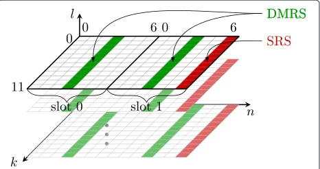
LTE operates on a time-frequency grid as shown in Fig. 1. The number of subcarriers is always a multi-ple of 12; 12 adjacent subcarriers over 7(or 6—in case of extended CP) successive OFDM symbols are called resource block (RB). Each RB thus consists of 12 × 7 (12×6) resource elements (REs), corresponding to the dif-ferent time-frequency bins. A detailed description of LTE up- and downlink is available, e.g. in [27].
Fig. 1The LTE-A uplink resource grid
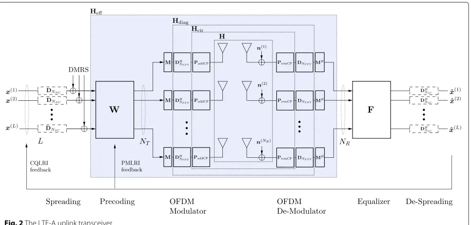
Right after the DFT spreading, the DMRS is inserted. The DMRS will be considered later for the purpose of channel estimation (CE). Next, MIMO precoding is carried out, exploiting a set of semi-unitary precod-ing matrices W, pooled in the precoder codebook W, as defined in [1]. For LTE-A uplink transmission, the precoding matrix applied for a given user is equal for all RBs assigned to this user. In case of spatial mul-tiplexing, each spatial layer is transmitted with equal power.
Each antenna is equipped with its own OFDM modula-tor, consisting of subcarrier mapping, inverse fast Fourier transform (IFFT) and a CP addition. To cope with the channel dispersion and to avoid Intersymbol Interference
(ISI), LTE employs a CP. As a result of multipath prop-agation, a previous symbol may overlap with the present symbol, introducing ISI and impairing the orthogonal-ity between subcarriers, i.e. causing Intercarrier Interfer-ence (ICI) [28]. Normal and extended CP lengths, with a respective duration of 4.7 and 16.7μs, are standardized, enabling a simple trade-off between ISI immunity and CP overhead.
At the transmitter, the processing occurs in a reversed order. First, the OFDM demodulation/FFT takes place to get back into the frequency domain. The immunity to multipath propagation (stemming from the CP) allows to employ one-tap frequency domain equalizersF without performance loss. At last, de-spreading delivers the data estimates.
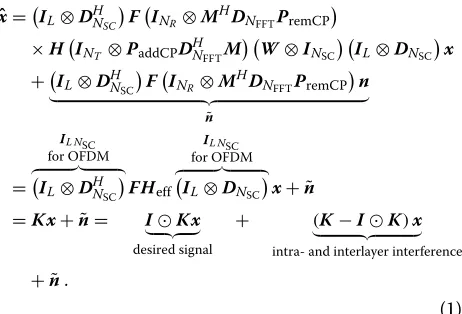
All this previously informally described processing is linear, and we are able to formulate a matrix-vector input-output relationship between a (stacked) data-vector x
and its estimate xˆ. For simplicity, we assume that the channel stays constant during one OFDM symbol. A detailed system description based on [29] can be found in [30].
In order to adapt the data transmission to the current channel state, LTE-A applies limited feedback; a com-prehensive specification follows in Section 4. Limited feedback is depicted via the feedback arrow in Fig. 2. The data vectorx(l) ∈CNSC×1of layerl ∈ {1,. . .,L}contains modulated symbols for each of theNSC subcarriers. The number of transmit layers depends on the LTE-A specific rank indicator (RI) feedback. The data symbols are coded with a punctured turbo code whose rate is determined by the channel quality indicator (CQI). Subsequently,
the codewords are mapped onto a quadrature amplitude modulation (QAM) alphabet (4/16/64 QAM), where the size of the alphabet depends on the CQI as well. All
x(l) are stacked into one vectorx ∈ CNSCL×1 on which layer-wise spreading and joint precoding—according to the precoding matrix indicator (PMI)—of all subcarriers take place. The subsequent OFDM modulator consists of the localized subcarrier mapping M, mapping NSC subcarriers to the centre of anNFFT point IFFT and the addition of the CP.
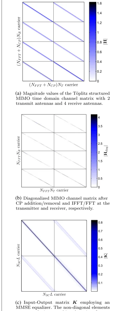
Depending on the level of abstraction, our sys-tem model can be described via different channel matrices. The physical baseband time domain chan-nel is described by a block-wise Töplitz matrix H ∈ C(NFFT+NCP)NR×(NFFT+NCP)NT, with NT transmit and NR receive antennas, which turns block-wise circulant (Hcir) after addition (PaddCP) and removal (PremCP) of an appro-priately chosen CP of lengthNCP. Finally, it turns diag-onal after the IFFT and FFT on the transmitter and receiver, respectively. An example of the Töplitz and diag-onal structured channel is demonstrated in Fig. 3a, b, respectively.
Hdiag=
INR⊗DNFFTPremCP
HINT⊗PaddCPD H NFFT
(2)
The last step of the OFDM de-modulator is the rever-sal of the localized subcarrier mappingMH. The effective MIMO channel from L transmit layers to NR receive antennas, incorporating the precoder, the OFDM modu-lator, the time-domain MIMO channelHand the OFDM de-modulator, is abstracted to one block matrix Heff. This greatly facilitates the readability of all formulas later on.
Heff=INR⊗M HH
diagINT⊗M W ⊗INSC
(3)
The additive noise is assumed independent across antennas and is distributed zero mean, white Gaussian
n(i) ∼ CN{0,σ2
nI}, i ∈ {1,. . .,NR}. The stacked noise
vector n = n(1)T,. . .,n(NR)T T is thus zero mean, white Gaussian as well.
The frequency domain one-tap equalizer3F is chosen conforming to different criteria, either the zero forc-ing (ZF) criterion, which removes all channel distor-tions at risk of noise enhancement, or the minimum mean squared error (MMSE) criterion, which tries to minimize the effects of noise enhancement and channel distortion.
After the de-spreading operation, the data estimates xˆ
of the noisy, received signal are given in Eq. (1), with the beforementioned convenient abbreviation (3), andDNFFT is the DFT matrix of sizeNFFT.
(a)
(b)
(c)
2.1 SC-FDM SINR
The special structure of Eq. (1), due to the frequency domain one-tap equalizer and the DFT spreading, yields a block-wise circulant input-output matrix, cf. Fig. 3c,
K =IL⊗DHNSC
This block-wise circulant structure produces a constant post equalization and post spreading SINR over all sub-carriers within one layer [30]. The detailed derivation is provided in the Appendix.
SINRSC-FDM,(l)= (5)
selects that part ofFHeffeffecting thelth layer. The sec-ond moment (power) of the zero mean transmit symbols is depicted byσx2.
2.2 OFDM SINR
In contrast to SC-FDM, no spreading takes place for OFDM. The dashed boxes in Fig. 2 are replaced by identity matrices; they are simply omitted. Thus, different sub-carrierskare orthogonal/independent and the equalizer treats the corresponding subcarrier channelHk only. We use the subscript k to denote the relevant part of the full channel matrixHeff for thekth subcarrier. The cor-responding indices within the diagonal matrixHdiag are 1NR×NT ⊗Diag(ek), with the canonical base vectorsek. Using this notation, the effective subcarrier channelHk∈
CNR×Lis andFk is its linear one-tap equalizer. The SINR formula is quite similar to the SC-FDM case, except that the SINR shows subcarrier dependency now. The SINR vector at layerlreads
with the selection vector
s(l)=0. . .0 1 0. . .0 , (9)
with appropriate number of zeros and a one at the lth position.
3 SC-FDM features
We first discuss the main reason to apply SC-FDM at uplink transmissions, namely PAPR. Then, we look at the
expenses of employing it. We will see a worse performance of the coded transmission.
3.1 Peak-to-average-power ratio
SC-FDM is employed as the physical layer modulation scheme for LTE uplink transmission, due to its lower PAPR compared to OFDM [31]. Lower PAPR, or similarly lower crest factor, leads to reduced linearity requirements for the power amplifiers and to relaxed resolution speci-fications for the digital-to-analogue converters at the user equipments, entailing higher power efficiency.
The Vienna LTE-A uplink simulator calculates the discrete-time baseband PAPR with the default oversam-pling factor J = 4 [32]. The discrete time signal on transmit antennat∈ {1,. . .,NT}is therefore calculated as
where x(pret) is the transmit vector right after precoding and before the IFFT at transmit antenna t. The PAPR
of the stacked vectorstx =
where the Euclidean norm in the denominator serves as an estimate for the ensemble average.
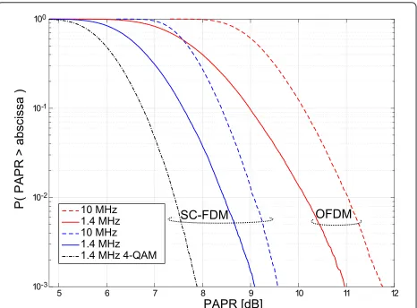
Figure 4 depicts the PAPR of OFDM and SC-FDM obtained for different system bandwidths. Already for a
small bandwidth (1.4 MHz), there is a significant reduc-tion for SC-FDM over OFDM. With increasing band-width, OFDM’s PAPR grows and the gains obtained by SC-FDM become more and more pronounced. The PAPR also depends on the modulation alphabet; the smaller the alphabet, the smaller the PAPR. This effect is illustrated in dotted lines in Fig. 4, where we have shown the PAPR of 4-QAM, exemplarily.
3.2 BER comparison over frequency selective channels
The additional spreading of SC-FDM leads to an SINR expression that is constant on all subcarriers as for single-carrier transmission, legitimating its name. The aim of this subsection is to analyse the SINR expression more care-fully for the SISO case4 and draw conclusions on BER performance.
We focus on the two most prominent equalizer concepts and start with the ZF equalizer, for whom the SC-FDM signal-to-noise ratio (SNR) expression (5) reduces to the harmonic mean
whereas the OFDM expression (8) is sub-carrier depen-dent and becomes proportional to the channel transfer function
The average OFDM SNR
SNROFDMZF = σ
yields an upper bound on the SC-FDMA SNR due to the harmonic mean—arithmetic mean inequality [33].
SNRSC-FDMZF ≤SNROFDMZF (15)
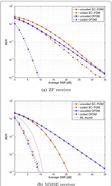
Equality in Eq. (15) holds if and only if the channel is fre-quency flat. The difference between the harmonic mean and the arithmetic mean gets increasingly pronounced, the more selective the channel becomes. We therefore expect the (uncoded) BER of SC-FDM and ZF equaliza-tion to perform worse than OFDM, which is also validated by simulations. The BER simulations were carried out with CQI = 4 on a PedB channel [34]. This modulation and coding scheme (MCS) employs 4-QAM and has an effective code-rate of 0.3008. As expected, the BER per-formance of SC-FDM is worse than OFDM, both shown in Fig. 5a in solid lines. Due to the spreading, SC-FDM already expends all channel diversity and coding does not increase the SNR slope of the BER curve. This manifests in an almost parallel shift of the BER curve for SC-FDM,
(a)
(b)
Fig. 5BER comparison between OFDM and SC-FDM for a SISO PedB channel with 5 MHz bandwidth and fixed CQI=4 transmission
as visual in Fig. 5a in red dashed lines. None exploited diversity allows coded OFDM to increase the BER slope considerably, cf. Fig. 5a blue dashed line.
The MMSE SINR expression is less intuitive and for the purpose of comparison, similar mathematical trans-formations as in [35] and [23] are required to arrive at
The detailed derivation is shown in the Appendix. The denominator of Eq. (16) is regularized and less sensitive to spectral notches.
An upper bound on the SINR can be obtained via the maximum of the transfer functionHk
SINRSC-FDMMMSE ≤ σ
2, this bound becomes
tight. The higher the inverse SNR σn2
σ2
x in relation to the maximum of the transfer function, the tighter the bound becomes. The average OFDM SNR can never be larger to its maximum entry and is only equal for frequency flat channels. At low SNR, a lower BER is thus expected. Again, this presumption is validated by our simulation, showing that the uncoded BER is lower for SC-FDM as for ODFM, cf. Fig. 5b in solid lines. Although the uncoded BER shows superior performance, the coded BER is lower for OFDM due to the coding gains stemming from chan-nel diversity, cf. Fig. 5b dashed lines.
A bound for the maximum likelihood (ML) detec-tion performance was derived in [36]. As the bandwidth increases, the slope of the BER curve achieved with MMSE receivers tends to the slope of ML detection, demonstrating the full exploitation of channel diversity by the MMSE equalizer, cf. Fig. 5b black line.
4 Link adaptation
In the previous section, we investigated BER performance of OFDM and SC-FDM transmission with different chan-nel models and receivers. We observed significant BER degradation of SC-FDM as compared to OFDM when ZF detection is employed, whereas coded BER is very similar when MMSE detection is used. In this section, we evaluate how such BER differences impact the actual through-put performance of LTE-A uplink when transmission rate adaptation is employed. We first consider ideal rate adap-tation and compare SC-FDM transmission to OFDM with ZF and MMSE receivers. Then, we extend our single-user MIMO CSI feedback algorithms proposed for LTE downlink in [37] to LTE uplink and evaluate their perfor-mance comparing to the throughput bounds developed in [24]. We also highlight some important basic differ-ences between link adaptation in LTE up- and downlink transmissions.
4.1 Performance with ideal rate adaptation
As demonstrated in the previous section, SC-FDM pro-vides a significant advantage in terms of PAPR over
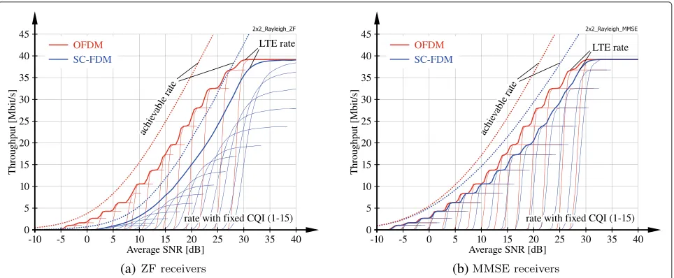
OFDM, thus relaxing linearity requirements of radio fre-quency power amplifiers for user equipments. Yet, this comes at the cost of coded BER degradation since channel diversity is lost and the performance is mostly dominated by the weakest subcarrier of a user, especially with ZF receivers; c.f. (12). This diversity loss cannot be recovered by forward-error-correction channel coding, since the DFT-spreading applied with SC-FDM effectively causes an averaging over SINR observed on all scheduled subcar-riers according to (5). As a consequence, SC-FDM trans-mission over frequency selective channels achieves worse throughput than OFDM. This is demonstrated in Fig. 6, where we cross-compare the achievable rate, as defined in (18) and (19), and the actual throughput of SC-FDM and OFDM transmission as obtained by the Vienna LTE-A Uplink Simulator. We consider single-user transmission over 5 MHz bandwidth assumingNT=NR=2 antennas at the user and the base station andL = 2 spatial layers. The precoder is selected as a scaled identity matrix:W =
1/√LIL. We consider transmission over independent and identically distributed frequency-selective Rayleigh fading channels, emphasizing the difference between OFDM and SC-FDM. The achievable rate in bits per OFDM/SCFDM symbol with Gaussian signalling and equal power allo-cation over subcarriers and spatial layers is calculated as
ROFDM=
with the receiver-specific post-de-spreading (post-equalization) SINRs from (5) and (8), respectively.
(a) (b)
Fig. 6Throughput comparison of OFDM and SC-FDM with rate adaptation and 2×2 Rayleigh fading channels of 5-MHz bandwidth
We also observe in Fig. 6a that the gain achieved by instantaneous rate adaptation, as compared to rate adap-tation based on the long-term average SNR, is much larger for ZF SC-FDM than for ZF OFDM; this is evident from the distance between the curves with rate adapta-tion (LTE rate) and the curves withfixed CQI. The reason for this behaviour is that the SNR of ZF SC-FDM shows strong variability around its means, since it is dominated by the worst-case per-subcarrier SNR according to (12); the average SNR over subcarriers of ZF OFDM, however, approximately coincides with its mean value. This implies that the optimal CQI of ZF SC-FDM can vary significantly in-between subframes, as reflected by the large average SNR variation required to increase the rate with fixed CQI from zero to its respective maximum. Yet, for ZF OFDM, the throughput of the individual CQIs follows almost a step function; hence, rate adaptation can be based on the long-term average SNR without substantial performance degradation.5
In caseNR > L, we can easily estimate the achievable rate of SC-FDM transmission: The per-layer SNR with ZF receivers is governed by the harmonic mean of the channel responses on the individual subcarriers, similar to (12)
SNRSC–FDM,ZF (l)= σ 2 x/σn2 1
NSC NSC
k=1
(HkW)H(HkW) −1
l,l ,
(20)
withHk ∈ CNR×NT denoting the OFDM channel matrix on subcarrierk. Assuming constant precoding and semi-correlated Rayleigh fading
Hk = ˜HkC 1 2 T,
˜
Hk
i,j∼CN{0, 1}, (21)
with CT ∈ CNT×NT determining the spatial correlation at the user equipment side, the matrix in the denomina-tor of (20) follows a complex inverse Wishart distribu-tion with NR degrees of freedom and scale matrixC =
WHCTW −1
H=(HkW)H(HkW) −1
∼CW−1
L {NR,C}. (22)
Letting NSC → ∞, we can replace the term in the denominator of (20) with its expected value
1 NSC
NSC
k=1
Hl,lNSC−→→∞EHl,l . (23)
This expected value only exists in caseNR>L[38]. For NR=L, the diagonal elements ofHfollow a heavy-tailed inverted Gamma distribution [39, 40] with non-finite first moment. Yet, forNR>L, which is a common situation in cellular networks since the base station is mostly equipped with far more antennas than the users, the expected value is
EHl,l = 1
NR−L
[C]l,l. (24)
Hence, we can estimate the achievable rate of SC-FDMA transmission over semi-correlated Rayleigh fading chan-nels
RSC-FDM≈NSCLl=1log2
1+σx2/σn2
[C]l,l (NR−L) (25)
≈NSCL
log2 σx2/σn2 !L
l=1[C]l,l
1/L
"
+log2(NR−L) #
Here, (26) resembles the high SNR approximation of the achievable rate of OFDM transmission with ZF detec-tion as proposed in ([41] Eq. (14)); even more, for fixed Land lettingNR grow to infinity, (26) and ([41] Eq. (14)) tend to the same limit, due to channel hardening on each subcarrier with growing number of receive antennas.
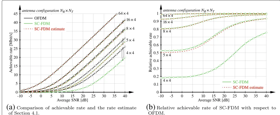
In Fig. 7, we investigate the performance of the rate esti-mate (25) forNT =L=4 and varying number of receive antennas. We assumeW =1/√LILand
CT = ⎡ ⎢ ⎢ ⎢ ⎢ ⎣
1 0.9 . . . 0.9
0.9 . .. ... ..
. 0.9
0.9 . . . 0.9 1 ⎤ ⎥ ⎥ ⎥ ⎥ ⎦,
and consider the smallest LTE bandwidth ofNSC = 72 subcarriers. We observe that the proposed estimate per-forms very well even at this small bandwidth; notice, though, that a more realistic channel model with corre-lation over subcarriers may require larger bandwidth to validate the proposed estimate. Figure 7 also confirms the observation that single-user MIMO OFDM and SC-FDM with ZF detectors tend to the same limiting performance with increasing number of receive antennas.
This statement, however, will not hold true if the total number of layers grows proportionally with the number of receive antennas. For example, multi-user MIMO trans-mission with ZF equalization and single-antenna users achieves only a diversity order ofNR−L+1 [42], with Ldenoting the total number of layers being equal to the number of spatially multiplexed users. Hence, ifLscales
proportionally withNR, channel hardening on each sub-carrier will not occur and thus the performance of OFDM and SC-FDM will not coincide.
4.2 Performance with realistic link adaptation
Instantaneous rate adaptation is an important tool for exploiting diversity of the wireless channel in LTE, by adjusting the transmission rate according to the current channel quality experienced by a user. LTE specifies a set of 15 different MCSs; the selected MCS is signalled by the CQI.
LTE additionally supports spatial link adaptation by means of codebook-based precoding with variable trans-mission rank. With this method, the precoding matrix
W ∈ CNT×L satisfying WHW = 1/LIL is selected from a standard-defined codebook WL of scaled semi-unitary matrices; furthermore, the number of spatial layers L can be adjusted to achieve a favourable trade-off between beamforming and spatial multiplexing. The selected precoder and transmission rank are signalled, employing the PMI and the RI. In single-user MIMO LTE uplink transmission, the same precoder is applied on all RBs that are assigned to a specific user, whereas frequency-selective precoding is supported in LTE downlink.
There is a basic difference between the utilization of CQI, PMI and RI in up- and downlink directions of fre-quency division duplex (FDD) systems. In the downlink, the base station is reliant on CSI feedback from the users for link adaptation and multi-user scheduling [43], since channel reciprocity cannot be exploited in FDD. CQI, PMI and RI can be employed to convey such CSI from the users to the base station via dedicated feedback channels [44]. In the uplink, on the other hand, the base station can by itself
(a)
(b)
determine CSI exploiting the sounding reference signals (SRSs) transmitted by the users. In this case, CQI, PMI and RI are employed by the base station to convey to the users its decision on link adaptation that has to be applied by the users during uplink transmission.
In principal, link adaptation must be jointly optimized with multi-user scheduling to optimize the performance of the system, since the effective SC-FDM SINR (and thus the rate) of a user depends on the assigned RBs according to (5). For reasons of computational complexity, however, we assume that the multi-user schedule is already fixed and determine link adaptation parameters based on this resource allocation. We modify the approach proposed in [37] for LTE downlink transmission to determine the link adaptation parameters in four steps:
1. Determine the optimal precoder for each
transmission rankL≤min(NT,NR)by maximizing
transmission rate
ˆ
W(L)=arg max
W∈WL
L
l=1 f
SINRSC-FDM,(l)(W) .
(27)
Here, functionf(·)maps SINR to rate; this could be either an analytical mapping, such as (19), or a mapping table representing the actual performance of LTE. In our simulations, we employ the bit interleaved coded-modulation (BICM) capacity as proposed in [37], since LTE is based on a BICM architecture.
2. Determine the optimal LTE transmission rates per layer for eachL andWˆ (L). We employ a target block error ratio (BLER) mapping in our simulations to determine the highest rate that achieves BLER≤0.1. 3. Select the transmission rankLˆthat maximizes the
sum rate over spatial layers, utilizing the LTE transmission rates determined above. 4. Set the RI and PMI according toLˆandWˆ(L),
respectively, and set the pCQI conforming to the corresponding LTE transmission rates.
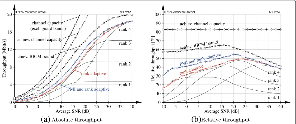
In Fig. 8, we evaluate the performance of single-user MIMO LTE uplink transmission over NT = NR = 4 antennas with link adaptation, 1.4 MHz system band-width and ZF receiver. We do not consider signalling delays between the base station and the user. We employ the VehA channel model [34] and compare the abso-lute and relative (to channel capacity) throughput to the performance bounds proposed in [24].6 Channel capac-ityis obtained by applying singular value decomposition (SVD)-based transceivers and water-filling power alloca-tion over subcarriers and spatial streams. Notice that we do not account for guard band and CP overheads when calculating the channel capacity; that is, we only consider subcarriers that are available for data transmission. The achievable channel capacitytakes overhead for pilot sym-bols (DMRS and SRS) into account, corresponding to a loss of 16.7 % in our simulation. The achievable BICM bound additionally accounts for equal power allocation, codebook-based precoding and ZF detection as well as the applied BICM architecture as detailed in [24].
(a)
(b)
The performance of LTE uplink transmission with full link adaptation (PMI and rank adaptive) is similar to the achievable BICM bound but shifted by approximately 3 dB. Notice that the saturation value is not the same because the highest CQI of LTE achieves 5.55 bit/channel use, whereas the BICM bound saturates at 6 bit/channel use. We also show the performance of LTE uplink when restricted to fixed precoding (rank adaptive) and fixed rank transmission (ranks 1, 2, 3, 4). We observe that rank adaptive transmission even outperforms the envelope of the fixed rank transmission curves, since instantaneous rank adaptation selects the optimal rank in each subframe independently. In terms of relative throughput, we see that LTE uplink with ZF receivers achieves around 40–50 % of channel capacity; remember, though, that this does not include CP and guard band overheads.
5 Reference symbols
In LTE uplink, two types of reference signals are standard-ized. For CE and coherent detection, DMRS are exploited, while SRS are employed for channel sounding to enable frequency selective scheduling. For the purpose of CE, we will consider DMRS only. The reference symbols are defined in [1] and are explained in more detail in [45, 46]. As shown in Fig. 9, DMRS are multiplexed in the resource grid at OFDM symbol time n = 3 in every slot. In a physical uplink shared channel (PUSCH) transmission of the LTE-A uplink, a DMRS occupies all scheduled sub-carriers. We assume that the user is assigned to allNSC subcarriers starting at 0, i.e.,k ∈ {0, 1,. . .,NSC−1}. We denote the Zadoff-Chu (ZC) base sequence onNSC sub-carriers for one slot byr¯∈CNSC×1. The base sequencesr¯ are complex exponential sequences lying on the unit circle fulfilling
|[r¯]k| =1 . (28)
In LTE-A, the DMRS of different transmission layers in the same slot are orthogonal in terms of frequency domain code division multiplexing (FD-CDM) [45]. This
Fig. 9The LTE-A uplink reference symbol allocation in two slots (one subframe)
is obtained by cyclically shifting the base sequence. Sim-ilar to [47], DMRS on layer l for one slot are given by
R(l)=Diag
r(l) =T(l)Diag(r)¯ , (29)
with the cyclic shift operator
T(l)=Diagej0,. . .,ejαlk,. . .,ejαl(NSC−1) , (30) and the layer dependent cyclic shiftαl. We further con-clude from (28) to (30) that (R(l))H = (R(l))−1 which implies
R(l) HR(l) = INSC. Exploiting (28), the product of two DMRS from layersl anduwith l,u ∈ {1,. . .,L} becomes
R(l) HR(u) =
T(l) HT(u)Diag(r¯)HDiag(¯r) (31)
= Diagej0 . . . ejαk . . . ejα(NSC−1) I,
withα = αu−αlbeing the cyclic phase shift between DMRS of two different spatial layers. The FD-CDM orthogonality can therefore be exploited as
trace
R(u) HR(l)
=r(u) Hr(l)=
NSC foru=l 0 foru=l.
(32)
After transmission over a frequency selective channel, this orthogonality has to be exploited to separate all effec-tive MIMO channels at the receiver.
6 Channel estimation
For channel estimation we exploit the system model only at symbol times, where reference signals are allocated. For a normal CP length, this is the 4th symbol in each slot, i.e.n = 3 as shown in Fig. 9. Since we estimate the channel only at this single symbol time per slot, inter-polation in time has to be carried out to obtain channel estimates for the whole resource grid. The effects of inter-polation will be studied in Section 7. As illustrated in Fig. 2, the DMRS are added after DFT spreading, right before precoding. As the channel estimation takes place after the receiver’s DFT, just before equalization, the sys-tem model for CE amounts to an OFDM syssys-tem. The system model (1) therefore reads as
y=Heffr+n, (33)
with (pre-equalization) noise
n=INR⊗M HD
NFFTPremCP
n, (34)
and the stacked vectorrconsisting of DMRSr(l)∈CNSC×1 from all active spatial layers l ∈ {1,. . .,L}, i.e. r =
according part fromyby left multiplying with the selec-tor matrixS(i)from (6). The received signaly(i)=S(i)yon antennaiis given by
y(i)=H(effi,1),. . .,H(effi,L) r+n(i) (35) mate a channel vector rather than a matrix and rearrange terms in (35) leading to
y(i)=
of all effective channels fromLactive layers
to receive antennaifor which we will drop the subscript in the following.
6.1 Minimum mean square error estimation
First, we present a MMSE estimator where we exploit (36) and estimate the stacked vectorh(i)consisting of effective channels from allLactive layers to receive antennai. The MMSE CE for receive antennaiis given by
ˆ
which leads to the well-known solution [48]
ˆ
As a low complexity approach, we correlate (matched fil-ter) the received signal with the reference symbol of layerl to obtain a channel estimate for the effective channelh(i,l)
from layerlto receive antennai
˜
h(i,l)=
R(l) Hy(i). (39)
In fact, this correlation approach is optimum in a least squares (LS) sense
Inserting our system model (36) and exploiting (31), we obtain is unitary and introduces phase changes only, cf. (29). Due to the allocation of DMRS on the same time and frequency resources on different spatial layers, the ini-tial estimateh˜(i,l)of one effective MIMO channel actually consists of a superposition of allLeffective MIMO chan-nels to receive antennai. The unintentional contributions in (41), from layers u = l are inter-layer interference, making it unsuited as initial estimate for coherent detec-tion. Different methods to separate the different effective MIMO channels in (41) will be presented in the following.
6.2.1 DFT-based channel estimation
A well-known approach for CE in LTE-A uplink is DFT-based estimation [46], which aims to separate the MIMO channels contributing to (41) in time domain. For this, the individual cyclic shift of each DMRS is exploited. Apply-ing a DFT on the receive signal, the individual phase shifts will translate into shifts in time domain. This makes a sep-aration of channel impulse response (CIR)s from different MIMO channels possible by windowing. In our simulator, we implemented a DFT-based estimator as in [49] or [47].
6.2.2 Averaging
For physically meaningful channels, neighbouring subcar-riers will be correlated within the coherence bandwidth [50]. We utilize this property and exploit the DMRS struc-ture to perform frequency domain CE. As explained in [25], applying a sliding averaging on the initial estimate
˜
h(i,l) from (41) over γ¯ adjacent subcarriers (γ¯ equals 1,2,4,4 forLequals 1, 2, 3, 4, respectively) cancels the inter-layer interference, assuming the channel to be frequency flat on theseγ¯ consecutive subcarriers. The sliding aver-age is given by
-forγ¯ ≤k≤NSC− ¯γ +1. The second sum describes the averaging ofγ¯elements while the first sum describes the shift of this averaging window.
6.2.3 Quadratic smoothing
Another method exploiting channel correlations to esti-mate the channel in frequency domain is quadratic smoothing (QS). This scheme cannot remove the inter-layer interference entirely, which manifests in a higher error floor, but shows improved performance at lower SNR in return. As explained in [25], this estimation method, exploiting the smoothing matrix Q and a smoothing factorγ, is given by
ˆ
h(QSi,l)=INSCL+λQ
HQ−1
R(l) Hy(i)
˜ h(i,l)
. (43)
Similar to (42), this can be interpreted as another way to cope with the inter-layer interference in (41) by post processing. This method does not use the DMRS structure explicitly but suppresses the interference by smoothing. It is therefore not able to cancel the complete inter-layer interference but shows an improved performance at low SNR.
6.3 MSE and BER comparison
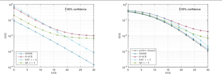
We assume a single user 2×2 MIMO transmission with NSC = 72 subarriers, a fixed number of layersL = 2 and a typical urban (TU) channel model [34] at zero speed. We perform a simulation with one-point extrap-olation, cf. Section 7, and show the MSE curves of the proposed estimators in Fig. 10a. The DFT-based CE (D-bCE) shows the highest error flow of all estimators at high SNR while the MMSE estimator of course shows
best performance over the whole SNR range. Compared to these two methods, the Sliding-Averaging estimator (42), denoted bySAV, encounters an 8-dB SNR penalty when compared to MMSE but comes closest toMMSE perfor-mance at high SNR. The quadratic smoothing estimation is denoted by QS and shows a significant improvement for low SNRs because it smooths over several observed channel coefficients. Quadratic smoothing performs uni-formly better thanD-bCE over the whole SNR range and comes close to 4 dB to MMSE at low SNR. The high error floor shows that QS is not able to cancel all the inter-layer interference.
In terms of BER performance, at high SNR, nat-urally the estimation method with the lowest MSE leads to the smallest BER. At low SNR, the differ-ence in CE MSE translates into very small differdiffer-ences in BER, meaning, we cannot gain too much from a good low SNR MSE performance of QS or MMSE estimation. Considering estimation complexity and that MMSE as well as QS require prior channel knowl-edge,SAV estimation is a good complexity performance trade-off.
7 Channel interpolation
Under fast fading conditions, additional effects influence the performance of LTE uplink transmissions. Doppler shifts degrade the SINR by introducing velocity dependent ICI [51] whereas the SINR increases with increasing sub-carrier spacing. The subsub-carrier spacing of 15 kHz that is used in LTE makes transmissions quite robust against ICI. The impact of ICI becomes only evident at high velocities and high SNR. Figure 12b shows the BER for the case of perfect channel knowledge where the performance is only degraded by noise and ICI. At 200 km/h, the BER saturates due to ICI at high SNR whereas ICI mitigation techniques
95% confidence 95% confidence
(a)
(b)
[52] show promising results to reduce this impact of ICI.
Another effect that hampers LTE transmissions at high velocities are temporal channel interpolation errors. While in the LTE downlink, the pattern used to mul-tiplex data and reference symbols is a good trade-off between a small temporal and spectral spacing account-ing for highly frequency selective channels and fast-fadaccount-ing channels and a rather small overhead, this is different in the uplink. As shown in Fig. 11a, uplink DMRSs occupy the whole subband. While there is no need for interpola-tion over frequency, the temporal spacing is about twice the spacing of the reference symbols in the downlink. Fur-thermore, if frequency hopping is performed, the number
(c)
(d)
(e) (b)
(a)
Fig. 11Channel interpolation techniques for the LTE-A uplink pilot patternausing estimates frombthe actual slot,cthe actual subframe andd–ethe actual and previous subframe
of adjacent pilots transmitted in the same subband is two for inter-subframe frequency hopping and only one for intra-subframe frequency hopping where frequency hopping is performed on a per-slot basis. Due to this spe-cial structure channel, interpolation in the LTE uplink is a challenging problem. Therefore, we investigated vari-ous channel interpolation techniques using a single, two or three consecutive pilot symbols. Figure 11b–e illus-trates the channel interpolation techniques considered. The highest channel interpolation errors (Fig. 12a) are observed for1 point extrapolationwhere the channel esti-mate obtained in a certain slot is used to equalize the symbols within that slot and no interpolation is performed at all. The higher the number of pilots involved in chan-nel interpolation, the lower the MSE gets. The results in terms of BER in Fig. 12b show a similar behaviour.
For a measurement-based comparison of interpolation techniques using channel estimates form both, the previous and the subsequent subframe, the reader is referred to [53].
8 Future research questions
Until now our research efforts on the Vienna LTE-A Uplink Simulator have been concentrated on single links between user and base station, focusing on basic transceiver issues such as link adaptation and channel esti-mation. Our treatment of the link performance analysis is not considered complete. There are still important param-eters to investigate, such as different forms of channel cod-ing, enhanced channel estimation and detection [54, 55] and analysis of SC-FDM sensitivity to synchronization mismatch, similar to our downlink investigations [56].
In the future, our scope will shift to user multi-base station scenarios, enabling on one hand exploita-tion of multi-user diversity in space, time and frequency and, on the other hand, consideration of interference in-between simultaneous transmissions from multiple base stations. Even though, for reasons of computational com-plexity, simulations will be confined to comparatively small scenarios containing some few base stations, we still expect to extract valuable performance indicators for coordinated multipoint reception schemes [57], account-ing for practical constraints, such as, limited back-haul capacity.
(a)
(b)
Fig. 12Comparison of channel interpolation techniques using different numbers of reference symbols and LS-SAV channel estimation
the uplink specifics and compare to other proposals, e.g. [58].
The realization of massive MIMO in LTE compliant sys-tems is another highly important research topic, since it promises an order of magnitude network efficiency gains through spatial multiplexing of users [59–61]. Yet, many issues still need to be better understood and resolved to enable efficient massive MIMO transmission in prac-tice. One important step towards reasonable performance investigation of massive antenna arrays is to employ real-istic channel models, such as, the 3GPP three-dimensional channel model [62], which we plan to incorporate in future releases of our simulator.
9 Conclusions
For an LTE-A uplink transmission model, we derived SINR expressions, both with and without DFT pre-spreading. We specialized these equations to ZF and MMSE receivers and showed that ZF performance is strongly affected by the worst subcarrier. Comparing the resulting BER we revealed that SC-FDM performance is generally inferior to OFDM and that applying MMSE equalization is crucial to get closer to OFDM perfor-mance.
Based on the system’s SINR, we analysed the achiev-able rate. We also introduced a method to estimate the SC-FDM rate for NR > L. Further, a possible calcula-tion of LTE-A link adaptacalcula-tion parameters was proposed to achieve throughout close to performance bounds.
Lastly, we considered methods to gather CSI at the receiver. We compared the performance of various channel estimation and interpolation techniques. By
incorporating the channel estimates of the previous sub-frame, we showed superior performance in terms of chan-nel interpolation.
Endnotes
1Note that we use the symbolnas time index and the vectornfor noise, the distinction should be clear from the context.
2Within this paper we focus on a single user’s link performance. Multi user / multi basestation simulations are possible to perform, but come at very long simulation times. For sake of readability we use the
non-standardized OFDM, SC-FDM notation in the remainder of this manuscript.
3A multi-tap equalizer applied on the intralayer interference visual in Fig. 3c could possibly enhance the link performance.
4The reduction to SISO is done to make our results comparable even to older frequency domain equalization (FDE) works, e.g., [63].
5Notice, however, that instantaneous rate adaptation for ZF OFDM can be advantageous in case of
frequency-correlated channels [44].
6Notice that the simulation setup is the same as employed in [24] for the investigation of LTE downlink transmission, thus, facilitating the comparison of up- and downlink performance.
Appendix
General MIMO SC-FDMA SINR expression
which acts on layer l by multiplying with the selector matrix S(l) from the left. As indicated in (1), the signal estimate consists of three contributions.
signal: xˆs=S(l)(IK)x
interference: xˆi=S(l)(K−IK)x
noise: xˆn=S(l)n˜
As x and n˜ are zero mean random quantities, their power is described by means of the second moment. To calculate the second moments, we take out the diagonal elements of the respective covariance matrices of each contribution.
Before, we derive the different covariance matrices, we recapitulate a required property of circulant matrices. A circulant matrixC ∈ CN×N is fully described by its first column c, as its eigenvectors are the DFT basis-vectors and its eigenvalues are the DFT ofc=(c0,c1,. . .,cN−1).
The main diagonal elementsc0ofCare given by
c0=
The input-output matrixKis of block-circulant structure, as illustrated in Fig. 3c. The eigenvalues of the diago-nal blocks are given by diag() = S(l)diag(FHeff) and the diagonal elements of thelth diagonal block are then
1
Assuming zero mean, white data with variance,
σ2
x the diagonal elements of E{ˆxsxˆHs } are given by
σ2
x|N11TS(l)diag(FHeff)|2.
E{ˆxixˆHi}: IfCis circulant
˜
is circulant as well and the diagonal elements ofC˜C˜Hare the sum of the magnitude squares ofc˜=(0,c1,. . .,cN−1). Using Parseval’s theorem, we arrive at
N−1
The inter-layer interference consists of L − 1 C-type blocks, where we simply average the magnitude squares of the eigenvalues, i.e. the corresponding block-part ofFHeff. The intra-layer interference is described via aC˜ block and is given in Eq. (50). Both contributions can be compactly written as
The noise covariance matrix is circulant as well and the detailed derivations can be found in [30].
SISO MMSE SC-FDMA SINR expression
For a SISO system and a one-tap equalizer, the expres-sionFHeffis of a diagonal shape. [30] has shown, that the MMSE equalizer for SC-FDM equals the OFDM
expres-sion, i.e. F = ments on the main diagonal ofFHeffare simply given by
|Hk|2 we have used the identity
from [23].
The authors declare that they have no competing interests.
Acknowledgements
This work has been funded by the Christian Doppler Laboratory for Dependable Wireless Connectivity for the Society in Motion and the Institute of Telecommunications, TUWien. The financial support by the Austrian Federal Ministry of Science, Research and Economy and the National Foundation for Research, Technology and Development is gratefully acknowledged.
Received: 8 September 2015 Accepted: 6 April 2016
References
1. 3rd Generation Partnership Project (3GPP), Evolved Universal Terrestrial Radio Access (E-UTRA) physical channels and modulation. TS 36.211, 3rd Generation Partnership Project (3GPP) (2015). 3rd Generation Partnership Project (3GPP)
2. S Schwarz, JC Ikuno, M Simko, M Taranetz, Q Wang, M Rupp, Pushing the limits of LTE: a survey on research enhancing the standard. IEEE Access.1, 51–62 (2013)
3. Y Yan, H Yuan, N Zheng, S Peter, inInternational Symposium on Wireless
Communication Systems. Performance of uplink multi-user MIMO in
LTE-advanced networks, (2012), pp. 726–730
4. C-H Pan, Design of robust transceiver for precoded uplink MU-MIMO transmission in limited feedback system. Wireless Personal Commun. 77(2), 857–879 (2014)
5. L Falconetti, S Landstrom, in8th International Symposium on Wireless Communication Systems. Uplink coordinated multi-point reception in LTE heterogeneous networks, (Aachen, Germany, 2011), pp. 764–768 6. Q Li, Y Wu, S Feng, P Zhang, Y Zhou, inIEEE 77th Vehicular Technology
Conference (VTC Spring). Cooperative uplink link adaptation in 3GPP LTE heterogeneous networks, (Dresden, Germany, 2013), pp. 1–5
7. Y Xue, Q Sun, B Jiang, X Gao, inIEEE 79th Vehicular Technology Conference (VTC Spring). Link adaptation scheme for uplink MIMO transmission with turbo receivers, (Seoul, Korea, 2014), pp. 1–5
8. E Dahlman, G Mildh, S Parkvall, J Peisa, J Sachs, Y Selén, J Sköld, 5G wireless access: requirements and realization. Commun. Mag. IEEE.52(12), 42–47 (2014)
9. C Mehlführer, JC Ikuno, M Simko, S Schwarz, M Rupp, The Vienna LTE simulators—enabling reproducibility in wireless communications research. EURASIP Journal on Advances in Signal Processing (JASP) special issue on Reproducible Research (2011)
10. N Baldo, M Miozzo, M Requena-Esteso, J Nin-Guerrero, inProceedings of the 14th ACM International Conference on Modeling, Analysis and Simulation of Wireless and Mobile Systems. An open source product-oriented LTE network simulator based on ns-3 (ACM, Miami, USA, 2011), pp. 293–298 11. G Piro, LA Grieco, G Boggia, F Capozzi, P Camarda, Simulating LTE cellular
systems: an open-source framework. IEEE Trans. Vehic. Technol.60(2), 498–513 (2011)
12. G Stea, A Virdis, G Nardini, inSIMULTECH 2014. SimuLTE: A modular system-level simulator for LTE/LTE-A networks based on OMNeT++ (insticc, Vienna, Austria, 2014), pp. 59–70
13. is-wireless, LTE PHY LAB (2015). http://is-wireless.com/4g-simulators/lte-phy-lab
14. H Zarrinkoub,Understanding LTE with MATLAB: from Mathematical Modeling to Simulation and Prototyping. (John Wiley & Sons, Hoboken, 2014)
15. G Gómez, D Morales-Jiménez, JJ Sánchez-Sánchez, JT Entrambasaguas, A next generation wireless simulator based on MIMI-OFDM: LTE Case Study. EURASIP J. Wireless Commun. Netw.2010, 15 (2010)
16. MV Lima, CM Gussen, BN Espíndola, TN Ferreira, WA Martins, PS Diniz, in
Acoustics, Speech and Signal Processing (ICASSP), 2012 IEEE International Conference On. Open-source physical-layer simulator for LTE systems (IEEE, Kyoto, Japan, 2012), pp. 2781–2784
17. M Taranetz, T Blazek, T Kropfreiter, MK Müller, S Schwarz, M Rupp, Runtime precoding: enabling multipoint transmission in LTE-advanced system-level simulations. IEEE Access.3, 725–736 (2015)
18. ITC, Vienna LTE-A Uplink Simulator (2016). https://www.nt.tuwien.ac.at/ research/mobile-communications/vienna-lte-a-simulators/lte-a-uplink-link-level-simulator/. [Online]
19. J Zhang, C Huang, G Liu, P Zhang, inCommunications and Networking in China, 2006. ChinaCom’06. First International Conference On. Comparison of the link level performance between OFDMA and SC-FDMA (IEEE, Beijing, China, 2006), pp. 1–6
20. D Sinanovi´c, G Šišul, B Modlic, inSystems, Signals and Image Processing (IWSSIP), 2011 18th International Conference On. Comparison of BER characteristics of OFDMA and SC-FDMA in frequency selective channels (IEEE, Sarajevo, Bosnia and Herzegovina, 2011), pp. 1–4
21. M Suarez, O Zlydareva, inUltra Modern Telecommunications and Control Systems and Workshops (ICUMT), 2012 4th International Congress On. LTE transceiver performance analysis in uplink under various environmental conditions (IEEE, St. Petersburg, Russia, 2012), pp. 84–88
22. JJ Sánchez-Sánchez, MC Aguayo-Torres, U Fernández-Plazaola, BER analysis for zero-forcing SC-FDMA over Nakagami-m fading channels. IEEE Trans. Vehic. Technol.60(8), 4077–4081 (2011)
23. JJ Sánchez-Sánchez, U Fernández-Plazaola, MC Aguayo-Torres, in
Broadband and Biomedical Communications (IB2Com), 2011 6th International Conference On. BER analysis for SC-FDMA over Rayleigh fading channels (IEEE, Melbourne, Australia, 2011), pp. 43–47 24. S Schwarz, M Simko, M Rupp, inSignal Processing Advances in Wireless
Communications SPAWC, 2011. On performance bounds for MIMO OFDM
based wireless communication systems, (San Francisco, CA, 2011), pp. 311–315
25. S Pratschner, E Zöchmann, M Rupp, Low complexity estimation of frequency selective channels for the LTE-A uplink. submitted to Wireless Communication Letters (2015). doi:10.1109/LWC.2015.2481428 26. Vienna LTE-A Simulators – LTE-A Link Level Uplink Simulator
Documentation, V1.4 (2015). https://www.nt.tuwien.ac.at/wp-content/ uploads/2016/01/LTEAlinkDoc_v1_5.pdf
27. E Dahlman, S Parkvall, J Sköld,4G LTE/LTE-Advanced for Mobile Broadband. (Elsevier Academic Press, Waltham, 2011)
intersymbol interference analysis of OFDM systems on time-invariant channels, vol. 4, (Lisboa, Portugal, 2002), pp. 1482–1487
29. A Wilzeck, Q Cai, M Schiewer, T Kaiser, inProceedings of the International ITG/IEEE Workshop on Smart Antennas. Effect of multiple carrier frequency offsets in MIMO SC-FDMA systems, (Vienna, Austria, 2007)
30. E Zöchmann, S Pratschner, S Schwarz, M Rupp, in19th International ITG
Workshop on Smart Antennas (WSA). MIMO transmission over high delay
spread channels with reduced cyclic prefix length, (Ilmenau, Germany, 2015)
31. HG Myung, J Lim, D Goodman, Single carrier FDMA for uplink wireless transmission. Vehic. Technol. Mag. IEEE.1(3), 30–38 (2006)
32. T Jiang, Y Wu, An overview: peak-to-average power ratio reduction techniques for OFDM signals. IEEE Trans. Broadcasting.54(2), 257 (2008) 33. PS Bullen,Handbook of Means and Their Inequalities. (Springer, Berlin, 2003) 34. Technical Specification Group Radio Access Network,Deployment Aspects.
(3rd Generation Partnership Project (3GPP), 2014). TR 25.943 Version 12.0.0, http://www.3gpp.org/DynaReport/25943.htm
35. MD Nisar, H Nottensteiner, T Hindelang, inMobile and Wireless Communications Summit, 2007. 16th IST. On performance limits of DFT spread OFDM systems (IEEE, Budapest, Hungary, 2007), pp. 1–4 36. M Geles, A Averbuch, O Amrani, D Ezri, Performance bounds for
maximum likelihood detection of single carrier FDMA. IEEE Trans. Commun.60(7), 1945–1952 (2012)
37. S Schwarz, M Rupp. IEEE International Workshop on Signal Processing Advances in Wireless Communications (SPAWC) (IEEE, San Francisco, CA, USA, 2011), pp. 316–320
38. D Maiwald, D Kraus, Calculation of moments of complex Wishart and complex inverse Wishart distributed matrices. IEEE Proc. Radar, Sonar Navigation.147(4), 162–168 (2000)
39. AK Gupta, DK Nagar,Matrix Variate Distributions.Monographs and surveys in pure and applied mathematics, vol. 104. (Chapman & Hall/CRC, Oregon, 2000)
40. R Xu, Z Zhong, J-M Chen, B Ai, Bivariate Gamma distribution from complex inverse Wishart matrix. IEEE Commun. Lett.13(2), 118–120 (2009) 41. DA Gore, RW Heath, AJ Paulraj, Transmit selection in spatial multiplexing
systems. IEEE Commun. Lett.6(11), 491–493 (2002)
42. A Hedayat, A Nosratinia, Outage and diversity of linear receivers in flat-fading MIMO channels. IEEE Trans. Signal Process.55(12), 5868–5873 (2007)
43. S Schwarz, C Mehlführer, M Rupp, inConference Record of the Forty Fourth Asilomar Conference on Signals, Systems, and Computers. Low complexity approximate maximum throughput scheduling for LTE, (Pacific Grove, California, 2010), pp. 1563–1569
44. S Schwarz, C Mehlführer, M Rupp, inWireless Advanced (WiAD), 2010 6th Conference On. Calculation of the spatial preprocessing and link adaption feedback for 3GPP UMTS/LTE, (London, UK, 2010), pp. 1–6
45. X Hou, Z Zhang, H Kayama, inIEEE 70th Vehicular Technology Conference Fall (VTC 2009-Fall). DMRS design and channel estimation for LTE-advanced MIMO uplink, (Anchorage, USA, 2009), pp. 1–5 46. X Zhang, Y Li, inInternational Conference on Connected Vehicles and Expo
(ICCVE). Optimizing the MIMO channel estimation for LTE-advanced uplink, (Beijing, China, 2012), pp. 71–76
47. C-Y Chen, DW Lin, inIEEE International Conference on Acoustics, Speech and Signal Processing (ICASSP). Channel estimation for LTE and LTE-A MU-MIMO uplink with a narrow transmission band, (Florence, Italy, 2014), pp. 6484–6488
48. SM Kay,Fundamentals of Statistical Signal Processing: Estimation Theory. (Prentice Hall, Upper Saddle River, 1993)
49. Q Zhang, X Zhu, T Yang, J Liu, An enhanced DFT-based channel estimator for LTE-A uplink. IEEE Trans. Vehicular Technol.62(9), 4690–4696 (2013) 50. B Sklar, Rayleigh fading channels in mobile digital communication
systems. i. characterization. Commun. Mag. IEEE.35(7), 90–100 (1997) 51. P Robertson, S Kaiser, inIEEE Vehicular Technology Conference, Fall. The
effects of Doppler spreads in OFDM (A) mobile radio systems, vol. 1 (IEEE, 1999), pp. 329–333
52. R Nissel, M Rupp, inProceedings of the IEEE International Conference on
Communications (ICC’15). Doubly-selective MMSE channel estimation and
ICI mitigation for OFDM systems, (London, UK, 2015)
53. M Lerch, inProceedings of Elmar 2015. Experimental comparison of fast-fading channel interpolation methods for the LTE uplink, (Zadar, Croatia, 2015)
54. R Nissel, M Rupp, in2015 IEEE International Conference on Communications (ICC). Doubly-selective MMSE channel estimation and ICI mitigation for OFDM systems (IEEE, 2015), pp. 4692–4697
55. G Berardinelli, CN Manchón, L Deneire, TB Sørensen, P Mogensen, K Pajukoski, inVehicular Technology Conference, 2009. VTC Spring 2009. IEEE 69th. Turbo receivers for single user MIMO LTE-A uplink (IEEE, 2009), pp. 1–5
56. Q Wang, C Mehlführer, M Rupp, in2010 IEEE 21st International Symposium on Personal Indoor and Mobile Radio Communications (PIMRC). Carrier frequency synchronization in the downlink of 3GPP LTE (IEEE, 2010), pp. 939–944
57. M Sawahashi, Y Kishiyama, A Morimoto, D Nishikawa, M Tanno, Coordinated multipoint transmission/reception techniques for LTE-advanced [coordinated and distributed mimo]. Wireless Commun. IEEE.17(3), 26–34 (2010)
58. N Abu-Ali, A-EM Taha, M Salah, H Hassanein, Uplink scheduling in LTE and LTE-advanced: tutorial, survey and evaluation framework. Commun. Surveys Tutor. IEEE.16(3), 1239–1265 (2014)
59. F Rusek, D Persson, BK Lau, EG Larsson, TL Marzetta, O Edfors, F Tufvesson, Scaling up MIMO: opportunities and challenges with very large arrays. IEEE Signal Process. Mag.30(1), 40–60 (2013)
60. L Lu, GY Li, AL Swindlehurst, A Ashikhmin, R Zhang, An overview of massive MIMO: benefits and challenges. IEEE J. Selected Topics Signal Process.8(5), 742–758 (2014)
61. E Larsson, O Edfors, F Tufvesson, T Marzetta, Massive MIMO for next generation wireless systems. IEEE Commun. Mag.52(2), 186–195 (2014) 62. 3GPP: TSG RAN; Study on 3D channel model for LTE (release 12) (2015).
http://www.3gpp.org/DynaReport/36873.htm
63. T Shi, S Zhou, Y Yao, inEmerging Technologies: Frontiers of Mobile and Wireless Communication, 2004. Proceedings of the IEEE 6th Circuits and Systems Symposium On. Capacity of single carrier systems with frequency-domain equalization, vol. 2 (IEEE, 2004), pp. 429–432
Submit your manuscript to a
journal and benefi t from:
7Convenient online submission
7Rigorous peer review
7Immediate publication on acceptance
7Open access: articles freely available online
7High visibility within the fi eld
7Retaining the copyright to your article