International Journal of Scientific Research in Computer Science, Engineering and Information Technology
© 2016 IJSRCSEIT | Volume 1 | Issue 2 | ISSN : 2456-3307
Analysis of Transformer less Inverter For Grid-Connected
Photovoltaic Power System Design
Lakshmi Narayana N1, Dr. Dalvinder Kaur Mangal2
1Research Scholar, EEE Department SUNRISE University, Alwar, Rajastan, India
2Professor Department of Electrical Engineering, SUNRISE University, Alwar, Rajastan, India
ABSTRACT
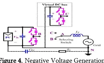
The traditional grid-connected PV inverter includes either a line frequency or a high frequency transformer between the inverter and grid. The transformer provides galvanic isolation between the grid and the PV panels. In order to increase the efficiency, to reduce the size and cost, the effective solution is to remove the isolation transformer. It leads to appearance of common mode (CM) ground leakage current due to parasitic capacitance between the PV panels and the ground. The common mode current reduces the efficiency of power conversion stage, affects the quality of grid current, deteriorate the electric magnetic compatibility and give rise to the safety threats. In order to eliminate the common mode leakage current in transformerless PV system, the concept of virtual DC bus is proposed in this project. By connecting the grid neutral line directly to the negative pole of the DC bus, the stray capacitance between the PV panels and the ground is bypassed. The CM ground leakage current can be suppressed completely. Virtual DC bus is created to provide the negative voltage level for the negative AC grid current generation. The virtual DC bus is realized with the switched capacitor technology that uses less number of elements. Therefore, the power electronic cost can be reduced. This topology can be modulated with the unipolar SPWM to reduce the output current ripple. A smaller filter inductor can be used to reduce the size and magnetic losses. The simulation result of the proposed topology using MATLAB/SIMULINK is presented.
Keywords: Common Mode Leakage Current, Transformerless Inverter, Unipolar SPWM.
I.
INTRODUCTION
Renewable energy sources become a more and more important contribution to the total energy production in the world. Today the energy production from solar energy compared to the other renewable energy sources is very low, but the pv systems are one of the fastest growing in the world. The price of pv system components, especially the pv modules are decreasing and the market for pv is expanding rapidly. Solar power will be dominant because of its availability and reliability. Photovoltaic inverters become more and more widespread within both private and commercial circles. These grid-connected inverters
bulky ac transformer. Both of these solutions offer the safety and advantage of galvanic isolation, but the efficiency of the whole system is decreased due to power losses in these extra components. In case the transformer is omitted, the efficiency of the whole pv system can be increased with an extra 1%–
2%. The most important advantages of
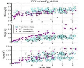
transformerless pv systems can be observed in Figure 1, such as higher efficiency and smaller size and weight compared to the pv systems that have galvanic isolation (either on the dc or ac side). Figure 1 has been made from the database of more than 400 commercially available pv inverters, presented in a commercial magazine about pv systems [1]. The efficiency of commercial pv panels is around 15-20%. Therefore, it is very important that the power produced by these panels is not wasted, by using inefficient power electronics systems. The efficiency and reliability of both single-phase and three single-phase pv inverter systems can be improved using transformerless topologies, but new problems related to leakage current and safety need to be dealt with. The size and cost of the inverter need to be reduced.
Figure 1. Advantages And Drawback Of Different Inverter Topologies
The efficiency of commercial PV panels is around 15-20%. Therefore, it is very important that the power produced by these panels is not wasted, by using inefficient power electronics systems. The efficiency and reliability of both single-phase and three phase PV inverter systems can be improved using transformerless topologies, but new problems related to leakage current and safety need to be dealt
with. The size and cost of the inverter need to be reduced. The main goal of this project is to analyze and model transformerless PV inverter systems with respect to the leakage current phenomenon that can damage the solar panels and pose safety
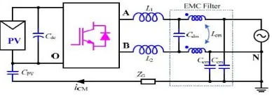
If the transformer is omitted, the common mode (CM) ground leakage current may appear on the parasitic capacitor between the PV panels and the ground [2] [3]. The existence of the CM current may reduce the power conversion efficiency, increase the grid current distortion, deteriorate the electric magnetic compatibility, and more importantly, give rise to the safety threats [4]. The CM current path in the
guarantee that vCM is constant or only varies at low frequency, such as 50Hz/60Hz line frequency.
Figure 2. CM Current Path For Transformer less PV Inverter
Figure 3. Equivalent circuit fr Current path
B. State-of-the-art Topologies
One of the way to realize this goal is to use full bridge inverter with the bipolar sinusoidal pulse width modulation (SPWM). Though the unipolar SPWM has better performance when compared to bipolar SPWM, it cannot be used directly for the full bridge inverter because it generates switching frequency CM voltage. For this reason, some of the topologies based on the full bridge inverter with unipolar SPWM such as the H5 inverter, the HERIC inverter, H6 inverter with AC bypass and H6 inverter with DC bypass have been developed. Such inverter topologies require two conventional half bridge inverter and neutral point clamped (NPC) half bridge inverter, then the inverter [7] are derived from the buck-boost and buck circuits respectively. These solutions have high reliability, but are not capable of supplying the reactive power to the grid. The inverter proposed in [8] employs a capacitor voltage divider to keep the CM voltage constant, but is regarded to be of higher conduction losses.
III.
NEGATIVE VOLTAGE GENERATION
Figure 4. Negative Voltage Generation
IV.
PROPOSED TOPOLOGY AND
MODULATION
Based on the negative voltage generation concept, an inverter topology is derived to show the clear advantages of the proposed methodology, which is shown in Fig.5. It consists of five power switches S1~S5 and only one single filter inductor Lf. The PV panels and capacitor C1 form the real DC bus while the virtual DC bus is provided by C2. With the switched capacitor technology, C2 is charged by the real DC bus through S1 and S3 to maintain a constant voltage. This topology can be modulated with the unipolar SPWM and double frequency SPWM. The detailed analysis is introduced as follows.
Figure 5. Proposed Topology
A. Unipolar SPWM
The waveform for the unipolar SPWM of the proposed inverter is displayed in Fig.6. The gate drive signals for the power switches are generated according to the relative value of the modulation wave ug and the carrier wave uc. During the positive half grid cycle, ug > 0. S1 and S3 are turned on and S2 is turned off, while S4 and S5 commutate complementally with the carrier frequency. The capacitors C1 and C2 are in parallel and the circuit rotates between state 1 and state 2 as shown in Fig.7. During the negative half cycle, ug < 0. S5 is turned
on and S4 is turned off. S1 and S3 commutate with the carrier frequency synchronously and S2 commutates in complement to them. The circuit rotates between state 3 and state 2. At state 3, S1 and S3 are turned off while S2 is turned on. The negative voltage is generated by the virtual DC bus C2 and the inverter output is at negative voltage level. At state 2, S1 and S3 are turned on while S2 is turned off. The inverter output voltage vAN equals zero, meanwhile C2 is charged by the DC bus through S1 and S3.
Figure 6. Unipolar SPWM For Proposed Topology
The summary of operation state of the switches for proposed topology is shown in Table 1.
Table 1. Summary Of Operation Of Switches
(a)
(c)
(d)
Figure 7. Operation States Of Proposed Topology : (A) State 1; (B) State 2; (C) State 3; (D) State 4
V.
MATLAB / SIMULINK MODEL
A. The Figure 8 shows the MATLAB / Simulink model for proposed inverter topology.
Figure 8. Simulink Model For Proposed Topology The Figure 9 shows the MATLAB / Simulink model for solar PV cell.
Figure 9. Simulink Model For Solar PV Cell
The Figure 10 shows the MATLAB / Simulink model for solar
Figure 10. Simulink model for unipolar SPWM
The Figure 11 Shows The Output Voltage Of Grid. The Value Of Grid Voltage Is 340V AC.
Figure 11. Waveform Of Grid Voltage The Figure 12 Shows The Output Current Of Proposed Inverter. The Value Of Current is 2.9 A.
Figure 12. Waveform Of Inverter Output Current
VI.
CONCLUSION
while the performance in eliminating the CM current is better than the full bridge based inverters. Based on this idea, a novel inverter topology is applications, where the output current is relatively small so that the extra current stress caused by the transformerless grid-connected PV inverters. The software tool used in this project is MATLAB 2011b.
VII.
REFERENCES
[1]. T.Kerekes, R.Teodorescu, P.Rodriguez, Vazquez, GE.Aldabas, "A New High-Efficiency Single-PhaseTransformerless PV Inverter Topology," Industrial Electronics, IEEE Transactions on , vol.58, no.1, pp.184-191, Jan. 2011.
[2]. O. Lopez, F.D. Freijedo, A.G. Yepes, P. Fernandez-Comesaa, J.Malvar, R.Teodorescu, J.Doval-Gandoy, "Eliminating Ground Current in a Transformerless Photovoltaic Application," Energy Conversion, IEEE Transactions on , vol.25, no.1, pp.140-147, March 2010.
[3]. E.Gubia, P.Sanchis, A.Ursua, J.Lopez, and L.Marroyo, "Ground currents in single-phase transformerless photovoltaic systems," Prog. Photovolt., Res. Appl., vol. 15, pp. 629– Photovoltaic Grid-Connected Power System," Power Electronics, IEEE Transactions
[6]. German Patent Wechselrichter: DE 19642522 C1, April 1998.
[7]. S.V.Araujo, P.Zacharias, R.Mallwitz,"Highly Efficient Single-Phase Transformerless "Unipolar PWM for transformerless grid-connected converters in photovoltaic plants," Clean Electrical Power, 2009 International Conference on , vol., no., pp.387-392, 9-11 June 2009.
[9]. Tarak Salmi, Mounir Bouzguenda, Adel Gastli, Ahmed Masmoudi "MATLAB/Simulink Based Modelling of Solar Photovoltaic Cell" International journal of Renewable Energy Research, Vol.2, No.2, 2012.R. Nicole, "Title of paper with only first word capitalized," J. Name Stand. Abbrev., in press.
[10]. T.Kerekes, R.Teodorescu, U.Borup