R E S E A R C H
Open Access
Polarization division multiple access with
polarization modulation for LOS wireless
communications
Bin Cao
1,2, Qin-Yu Zhang
1*and Lin Jin
1,3Abstract
In this paper, we discuss a potential multiple access and modulation scheme based on polarized states (PS) of electromagnetic (EM) waves for line-of-sight (LOS) communications. The proposed scheme is theoretic different from the existing polar modulation for EDGE and WCDMA systems. We propose the detailed bit representation (modulation) and multiple access scheme using PS. Because of the inflexibility of polarization information in the time and frequency domains, as well as independence of frequency and space, the polarization information can be used independently for wireless communications, i.e., another independent resource domain that can be utilized. Due to the independence between the PS and the specific features of signals (such as waveform, bandwidth and data rate), the discussed polarization division multiple access (PDMA) and polarization modulation (PM) are expected to improve the spectrum utilization effectively. It is proved that the polarization filtering technique can be adopted in the PDMA-PM wireless communications to separate the multiuser signals and demodulate the bit information representing by PS for desired user. Some theoretical analysis is done to demonstrate the feasibility of the proposed scheme, and the simulation results are made to evaluate the performance of the suggested system.
Keywords:polarized states, polarization division multiple access, polarization modulation, polarization filtering
1. Introduction
Multiple access technique which is oriented from the pioneering contributions of Shannon and Abramson [1-3], is a key feature for modern wireless communica-tions and its networking design. With the exponentially growing demand of users, such as in cellular system, to implement the target of “anybody can communicate with anyone at anywhere via any communication scheme“, the researchers are focusing on the multiple access technique design, wherein, frequency division multiple access (FDMA) used in the first wireless sys-tems, time division multiple access (TDMA) used in the second wireless systems [4], code division multiple access (CDMA) used in the second and third wireless systems [5], orthogonal frequency division multiple access (OFDMA) used in the LTE, WiMAX, and the fourth wireless systems [6], and the interleave division
multiple access (IDMA) which is a promising method for the next generation wireless systems [7] are pro-posed and implemented in practical military and civil systems. They use frequency, time, code, and interleaver as resources for multiuser allocation.
As known to all, any electromagnetic (EM) waves radiated by certain antenna with some polarization mode hold polarization characteristics, and any polar-ized state (PS) can be represented by two orthogonal components, thereby we know the orthogonally dualpo-larized antenna (ODPA). Polarization information denotes the relationship of amplitude and phase differ-ence between the two orthogonal components radiated by the ODPA, such as the vertical polarization and the horizontal polarization components or +45° linear polar-ization and -45° linear polarpolar-ization components. Suc-cessful application of polarization in the optical communications shows its special merits [8-11], while optical communications are different from wireless com-munications due to the transmitting medium and chan-nel. For wireless communications, channel is the key
* Correspondence: [email protected]
1
Communication Engineering Research Center, Shenzhen Graduate School, Harbin Institute of Technology, Shenzhen, Guangdong, 518055, P. R. China Full list of author information is available at the end of the article
role to the system design. Therefore, the system design methodology of wireless communications is different from that of optical communications when taking polar-ization into consideration.
Polarization of EM waves holds the unique feature that it is invariant in the time and frequency domains, as well as it is independent of frequency and space domains. While polarization does not attract much attention in wireless communications until some new findings, such as six-polarization, polarization filtering (PF) and polarization diversity, have been researched and applied [12-23]. Considering the applications of PF in radar and wireless communications for example [17-23], the usage of polarization extends the available resource domains when dealing with interference sup-pressions and signal separations problems.
Commonly used resources are time, frequency, space and code domains, and the corresponding applications are TDMA, FDMA, space division multiple access (SDMA), CDMA, OFDMA, and IDMA. Recently, some designs based on polarization are researched and devel-oped [24-31], such as polar modulation in the enhance data rates for global evolution (EDGE) system focusing on overcoming the problems of high power consump-tion, low efficiency, excessive heat and short battery life due to the requirement of linear power amplifier when
adopting3π
8 -8PSK modulation technique. In the exiting
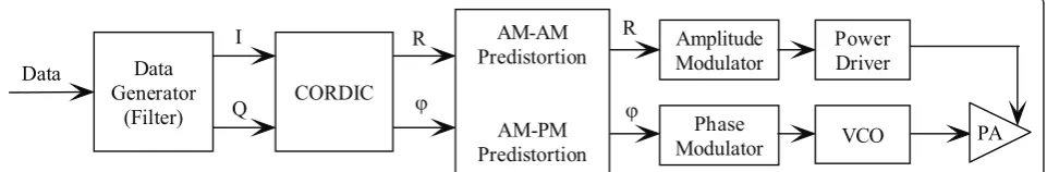
polar modulation introduced into EDGE, the orthogonal output fromI/Qchannels is transformed into the polari-zation format, i.e., one is the amplitude component and the other is the phase component before being sent to the transmitter, as shown in Figure 1. This makes the radio frequency circuit (in saturation mode) and the power amplifier can modulate the linear but non-con-stant-envelope signal which has the advantages of small electric current and high utilization efficiency. Another aspect of the use of polar modulation is that future wireless communications requires multimode radio transceivers, i.e., flexible capability with low power con-sumption. In [31], the authors discussed the multimode capability and low power consumption of polar modula-tion based systems by a prototype design of a GSM, EDGE, and WCDMA polar transmitter. The efficiency
of the polar transmitter is shown as a key enabler of future systems using OFDM scheme with high peak-average-power ratio (PAPR) signals.
In this paper, we take a new angle of view at the application of polarization for wireless communications. We propose a novel multiple access and modulation scheme [polarization division multiple access (PDMA) and polarization modulation (PM)] using polarization which is theoretically different from the above-men-tioned polar modulation for short range wireless com-munications, and the application scenario is assumed as a line-of-sight (LOS) wireless communications. If trans-mitter and receiver are in non-LOS, then the PS changes after reflecting, diffracting, and scattering by objects, and the phenomenon analysis is considerably complicated due to the dielectric parameter of the reflector. For the analysis of dielectric parameter, it is out of scope of this work. Hence, we analyze the appli-cation of the proposed PDMA-PM in LOS scenario.
The proposed scheme holds no relationship with the parameters of the signals, because the polarization is independent of the waveform. The bit information is carried by a pair of orthogonal PS of EM waves in the binary modulation, while bits of quaternary modulation is implemented by a set of orthogonal polarization and cross-polarization, and other high-order modulation schemes can be extended in a straightforward way. Dif-ferent users can be distinguished through making use of different PS. Furthermore, we can also combine the pro-posed PDMA with the FDMA, i.e., PDMA-FDMA, or to overcome the problem of high PAPR in OFDMA sys-tems, we can also utilize PDMA-OFDMA. It is proved that the desired signal can be achieved and demodulated by taking advantage of PF technique. From another point of view, it can be used independently besides the time, frequency, space and code domains. Furthermore, high spectrum utilization efficiency is expected to be obtained. Some theoretical deduction and analysis are done to demonstrate the feasibility of the suggested method, and the simulation results are made to show the effectiveness of the proposed scheme.
To the best of our knowledge, this is the first work that applies PS to wireless communications for modula-tion and multiple access design. The existing applicamodula-tion
of PS is in the field of optical communications, and Polar modulation is used to solve problems of high power consumption, low efficiency, excessive heat and short batter life due to the requirement of linear power amplifier for 8PSK modulation in EDGE system, there-fore, the modulation scheme is still the conventional 8PSK.
The main contribution of this work is threefold. (1) This is the first work that uses PS as the modulation scheme for wireless communications, and we demon-strate binary modulation and quaternary modulation by using orthogonal polarization and cross polarization. (2) We first use the PS as the multiple access scheme to support multi user wireless communication in LOS environment. (3) We establish the system by using only PS information, i.e., from transmitter to receiver and its signal processing.
The remainder of this paper is organized as follows. System model and fundamental principles are intro-duced in Section 2. The detailed analysis is demon-strated in Section 3. Finally, concluding remarks are drawn in Section 4.
2. System model and fundamental principles 2.1. Representation of polarization
Since the key concept of the PDMA-PM is based on the use of PS, we are revisiting the polarization in EM waves in this subsection. When representing a comple-tely polarized EM wave in a right-handedxyz Cartesian coordinate system with the z coordinate representing the direction of propagation and thexycoordinates be orthogonal basis defined by a pair of horizontally (H) and vertically (V) polarized unit vectors, the signal by ignoring the absolute phase can be described as the fol-lowing equation [19]
E(t) =
EH(t)
EV(t)
=
Ecosεexp(jωt) Esinε exp[j(ωt+δ)]
(1)
where ε is the amplitude relationship (or polarized angle) between the two components of the signal, δ represents the difference of them in phase (or phase difference in polarized angle), in addition,ωis the cen-ter frequencies of the signal, and E denotes the envelope.
The PS is determined by the amplitude and phase relationship between the two components received by the ODPA. Then the two parameters can be derived as
ε= arctan |Ev(t)|
|EH(t)|
(2)
δ= arg{EH(t)} −arg{EV(t)} (3)
where arg{x} indicates the argument of vectorx. After being radiated by the ODPA, the EM wave may produce the so-called cross-polarization (XP) component whose polarization is orthogonal to the original transmitting polarization, and this is the effect of depolarization [22]. The degree of depolarization is described by cross-polar-ization discrimination (XPD) which indicates the ratio of the original transmitted polarization component power and cross-polarization component power at the same location point. Depolarization effect can be eliminated by introducing depolarization compensation technology [32]. There are also many methods for estimation of PS (see, for example, [33,34]). We assume that the polarized state is already known at the receiver in this paper. Since we are considering the scenario of LOS, then the PS is not changed at a high probability. The phenom-enon of PS changes due to the reflecting, scattering, and diffracting by objects is outside of scope in this paper. Therefore, we only consider its application in LOS environment.
Polarized angle and phase difference in polarized angle determine the polarized state of the signal as follows: (1)
If δ= 0,π, the polarization is linear. (2)δ=−π 2,ε=
π
4
indicates the right-handed circular polarization, and
δ=−π 2,ε=
π
4 shows the left-handed circular
polariza-tion. (3) IfδÎ (0, 90°) andεÎ(0, 90°), then the polari-zation is left-handed elliptic. WhenδÎ (-90°, 0) andε Î(0, 90°), the polarization is right-handed elliptic.
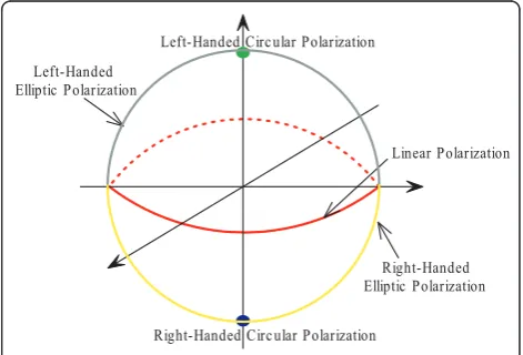
We can also denote the PS on the Poincare spherical surface as shown in Figure 2, where the north pole (green point) is the left-handed circular polarization, and the south pole (blue point) represents the right-handed circular polarization, then the equator (red cir-cle) indicates the linear polarization. The surface of the northern semi-sphere (gray color but excluding the
Left-Handed Circ ular Polarization
Right-Handed Circ ular Polarization
Linear Polarization Left-Handed
Elliptic Polarization
Right-Handed Elliptic Polarization
north pole and equator) denotes the left-handed elliptic polarization, while the surface of the southern semi-sphere (yellow color but excluding the south pole and equator) denotes the right-handed elliptic polarization. It establishes the one-to-one mapping between the polarized state and each point on the Poincare-spherical surface, and there are infinite PSs intuitively.
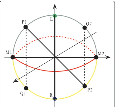
In Figure 3, the orthogonal polarization and the cross polarization are illustrated. Two points on the surface of the sphere are potential orthogonal polarization repre-sentations if the line joining them passes through the center of the sphere, for example the pairs (P1, P2), (Q1, Q2), (M1, M2), and (L, R), as shown in Figure 3. Contrarily the two points on the surface of the sphere are cross polarization representations if they are symme-trical about the surface of equator, such as pairs (P1, Q1), (P2, Q2) and (L, R). It can be found that the ortho-gonal polarization and the cross polarization are the same for circular polarization.
2.2. Binary modulation
As depicted in Figures 2 and 3, bit information can be carried by the PS, and the PS is determined by the amplitude and phase of the two components radiated by ODPA. Hence, each user can use certain PS when it wants to transmit information to the receiver. For exam-ple, circular polarization is allocated to some user, if the polarization is a left-handed circular one, then bit 1 is transmitted, and the right-handed circular polarization carries bit 0. This binary modulation scheme can be extended by exploiting different polarizations. We can also use the vertical polarization and the horizontal
polarization or +45° linear polarization and -45° linear polarization to carry binary information. We can see that the transmitter complexity is simple.
Figure 4 shows a circle with the center of the sphere as its center, since the orthogonal polarization and cross polarization are on the same circle. For simplicity, circu-lar pocircu-larization representations are on this circle. Then we can allocate different polarizations for different users. Taking User4 in Figure 2 for example, linear polarization is allocated to User4, and the bit informa-tion can be carried by the two orthogonal linear PS (yel-low pints) as shown in the figure. Other users can also use the linear polarization by properly adjusting the polarized angles. It can be found that it is an orthogonal modulation scheme for binary modulation in PDMA-PM systems since the PSs for bits 1 and 0 are orthogo-nal, while different users hold non-orthogonal polariza-tions with each other.
2.3. Quaternary modulation
Binary modulation can be easily extended to quaternary modulation by introducing cross-polarization. Figure 5 illustrates the constellation of the quaternary modula-tion. For User1, four blue points represent bits 00, 01, 11, 10, respectively, and the polarization for 00 and 11 is a pair of orthogonal polarization, the same for 01 and 10. The polarization for 00 and 10 is a pair of cross-polarization, the same for 01 and 11. Different users can be separated by rotating the rectangle with different angles.
Other high-order modulation schemes can be extended in a straightforward way. It is easy to find that we can also combine the PDMA with conventional FDMA and OFDMA, for example, some users share the same frequency band and other users share another
L
R P1
P2 Q1
Q2
M1 M2
Figure 3Representations of orthogonal polarization and cross polarization in Poincare-Sphere form.
User1 1
User1 0 User2 1
User20
User3 1
User3 0
User4 1 User4 0
UserK 1
UserK 0
frequency band. The multiple access technique of PDMA-FDMA is easy to implement.
Since the polarization is nothing with the specific waveform, bandwidth, rate, then the proposed PDMA-PM scheme is not strict with the waveform design, band-width limitation and other restrictions. Hence, it is expected to improve the spectrum efficiency, while the perfect implementation relies on the precise polarization measurement.
3. Detailed analysis
In this section, some detailed analysis and mathematical deduction are done to demonstrate the PDMA-PM. Here, we take the binary modulation as an example, and analyze its multiuser separation, demodulation and BER performance. Especially, we assume that all of the polar-ization states allocated to different users are available at the receiver.
Figure 6 depicts the simple block diagram of the transmitter. Consider there are Nusers in the system, the transmitting signal for thenth user is derived as
sn(t) =Ping(t) (4)
wherePin(i= 0, 1,n= 1, 2, ...,N) shows the PS
repre-senting bit 1 or bit 0 for thenth user, andPin= [cosεin,
sinεinexp(jδin)]T, where cosε0n+ cosε1n=π/2,δ0n-δ1n
=±π. This is the sufficient and necessary condition for a pair of orthogonal polarization.g(t) is the transmitting waveform for all the users. Then the received signalr(t) is the sum ofNusers, i.e.,r(t) =Nn=1sn(t) +n(t), n(t)is
the additive white gaussian noise (AWGN) with zero mean and the variance ofs2.
Figure 7 shows the block diagram of the receiver, where NPE is the estimation of the noise power,E0andE1are
the oblique projection operators constructed by the polari-zation states of 0 and 1, respectively, to cancel the interfer-ence [20-23].H0andH1are the operators of polarization
filtering.Ddenotes the decision process, here decision is the comparison of the output value between the two branches. Detailed introduction is as follows.
3.1. Multiuser separation in PDMA-PM
Since there areNsignals embedded in the received sig-nal, in order to suppress the unwantedN- 1 signals, PF is adopted here. The received signal can be rearranged in the matrix form
r(t) =[Pi1,Pi2, . . ., PiN]g(t) (5)
whereP0n,P1nis a pair of orthogonal polarization.
Suppose the first user is the desired signal. In order to suppress other N - 1 signals, PF can be used. The authors proposed oblique projection PF (OPPF) techni-que in [20-23], we just briefly introduce the OPPF here.
For simplicity, consider there are two users (N= 2). We can construct a filter with the operator written as
E=U(UHP⊥SU)−1UHP⊥S = 1
γ
A, B C, D
(6)
where U and S are the polarization states of the desired signal and interference, respectively. PS⊥ is the orthogonal projection operator onto the complementary ofS. Suppose the first and the second users are operat-ing at the same time, then the elements ofEare
γ = (cosεi1sinεi2)2+ (sinεi1cosεi2)2 −2 sinεi1sinεi2cosεi1cosεi2cos(δi2−δi1)
(7)
User1 00 User1 01
User1 10 User1 11
UserK 00
UserK 01
UserK 11
UserK 10
Figure 5Representation of quaternary modulation in Poincare-Sphere form.
Pow er Splitter
Phase Shifter Data
Controller Data
Sinal Sourc e
ODPA
Figure 6 Transmitter block diagram of the proposed PM system.
E0
E1
H0
H1
Input Signal Output Bit
NPE D
A= (sinεi2cosεi1)2−sinεi2cosεi2sinεi1cosεi1ej(δi2−δi1)(8)
B= cos2εi2sinεi1cosεi1e−jδi1−cos2εi1sinεi2cosεi2e−jδi2(9)
C= sin2εi2sinεi1cosεi1ejδi1−sin2εi1sinεi2cosεi2ejδi2 (10)
D= (sinεi1cosεi2)2−sinεi2cosεi2sinεi1cosεi1ej(δi1−δi2) (11)
respectively.
It is easy to prove that
Er(t) =Pi1g(t) =s1(t) (12)
sinceEPi1 =Pi1 andEPi2= 0. This shows the
interfer-ence can be suppressed totally by OPPF.
It is easy to find that if both the two user’s PSs are available, then the OPPF can perfectly separate them. While if there is uncertainty with the other user’s PS, i. e., there is estimation error in the PS of the other user, then the OPPF cannot separate them totally. In order to deeply understand the performance of the OPPF, we give the SIR analysis here.
The signal-to-interference (SIR) ratio of the received signal SIRi1 is
SIRi1= 20lg|
Ei1|
|Ei2|
(13)
Since there is estimation error on polarized angle of interference, the OPPF operator is not an accurate one. Suppose the parameters in formulae (8-11) are A1, B1,
C1andD1, the SIR after OPPF is
SIRo= 20lg|
Ei1(cosεi1B1+ sinεi1C1)| |Ei2(cosεi2B1+ sinεi2C1)|
(14)
The gain of SIR is
SIR = SIRo−SIRi= 20lg|
sin(εi1−εi2−εi2)| |sin(ε−i2|) (15)
The formula listed above shows that the gain of SIR ratio has relationship with the difference between polar-ized angles of the target signal and interference i.e.,εi1
-εi2, and the error deviation on polarized angle of
inter-ference, i.e., Δεi2. The larger the εi1 - εi2 is, the larger
the ΔSIR can be obtained. In order to get good ΔSIR performance, the moderately large difference between the polarized angles of the target signal and interference should be designed.
If the polarization of interference is not available at the receiver, another form of OPPF can be written as
E=U(SHRxx†U)−1UHRxx† (16)
Where
Rxx=Rrr−σ2E= [U,S]
RUU 0
0 RSS
[U, S]H (17)
and
Rrr=E{rrH}
=E ⎧ ⎨ ⎩[
N
n=1
sn+n][ N
n=1
sn+n] H⎫⎬
⎭
=E{(x+n)(x+n)H} =Rxx+σ2E
(18)
As shown, if the noise power is known exactly, then the OPPF can also separate the two users’signals. Here, we give the SIR analysis if the noise variance is not exactly estimated. The similar analysis of SIR enhance-ment can be obtained as
SIR =SIRo −SIRi
= 20lg|
σ2
σ2 −
E2i2
σ2sin 2(ε
i1−εi2)| |σσ22cos(εi1−εi2)|
(19)
Therefore, E0 is the oblique projection operator
(OOP) which can remain the component of the polari-zation representing 0 while suppressing the interference due to the property of the OOP, andE1can remain the
component of the polarization representing 1 while sup-pressing the interference. As shown in Figure 5, the input signal (received signal) passes through both E0
and E1, then the interference is canceled. This is the
multiuser separation process.E0and E1 for the first user
can be designed as
E0=P01(P01HRxx†P01)−1P01HRxx† (20)
as
E1=P11(P11HRxx†P11)−1PH11Rxx† (21)
3.2. Demodulation in PDMA-PM
After the separation process, the interference is sup-pressed, and the next step is to demodulate the bit information. Suppose bit 1 is transmitted, i.e., P11. It is
easy to obtain
E1(P11+Pi2) =P11 (22)
polarization representing 0, then afterE0, the output is
another vector even ifPi2is suppressed, since
E0(P11+Pi2)=P11 (23)
H0andH1are the operators of PF, and they meet the
conditions
H0•P01= 0 H0•P11= 1 (24)
H1•P11= 0 H1•P01= 1 (25)
where · denotes the dot product. These conditions show H0 is the orthogonal complementary of the
polari-zation representing bit 0, and the same forH1.
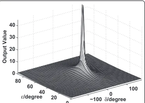
If bit 1 is transmitted, then afterE1 andH1, the
out-put value will be zero since P11 is invariable after E1,
and it is suppressed afterH1due to the property. While
the output after E0 andH0 is not zero since H0 is not
orthogonal to the output vector afterE0 when bit 1 is
transmitted. Figure 8 shows the output value after E0
andH0 when bit 1 is transmitted, the absolute value is
large than 0. If the transmitting energy is large, i.e., the signal-to-noise ratio (SNR) is high, then the absolute value is far away from 0 if they are not orthogonal.
Hence, we can select the minimum output value as the desired bit, i.e., when the output after E1and H1 is
the minimum value, then we can decide that 1 is trans-mitted, the same analysis for bit 0.
3.3. Impact of noise
For AWGN, its polarization is called non-polarized which means it holds all of PS, i.e., covers the whole Poincare-Sphere surface. In the analysis of demodulation, we use OPPF to separate multi user signals and extract bit infor-mation. From the signal processing point of view, the OPPF is a kind of notch filter that can set one or several
notches for some PS, then those PS are nulled by these notches. From this sense, the noise component which holds these PS are suppressed at the same time which shows that this method is capable of denoising. But the answer is no, since according to the oblique projection theory [35], AWGN can be even amplified after oblique projection which can be demonstrated in Figure 9.
In this figure, subspace His the desired subspace and S is the interfering subspace that need to null. Suppose they are not orthogonal then oblique projec-tion can be used to cancel any components in Swhile keeping everything in H. Since AWGN lies in every subspace (it is full rank and rank is infinity), the com-ponent of AWGN in subspace S is suppressed while some other components lie in other subspaces and will be amplified after oblique projection as shown in Fig-ure 9. We can determine its lower bound and upper bound by calculating the principal angles of the sub-spaces [35]. When subsub-spaces Hand S are orthogonal, then AWGN is not amplified since it is an orthogonal projection, and this is the lower bound. If the angle between H and S is zero which means they are the same subspace, then everything is nulled but noise, and this is the upper bound.
From the above analysis, if the principal angles of polarization subspace for multiple users are small, then the impact of noise will be significant. Even though we can set infinite PS for multi users, but from the noise impact point of view, this will lead to performance dete-rioration since the principal angles of large number of users are small.
3.4. BER performance of PDMA-PM
When bit 1 is transmitted, the error decision is made when the output of the first branch yais smaller than
the second branchyb, i.e., the output afterH0 is smaller
than that ofH1, then the probability of error is
Pe=Q
4Eb
HT0H0σ2
(26)
where m =ya - yb, and Ebis the energy of one bit.
The coefficient of||HT0H0||is due to the rule of oblique projection amplifying the noise which has been analyzed in the above section.
−100 0
100
0 20 40 60 80 0 10 20 30 40
δ/degree ε/degree
O
utput Value
Figure 8 Absolute output value after E0 when bit 1 is
transmitted.
H
S
v
E
HSv
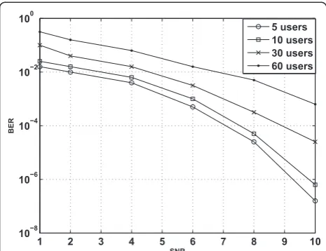
Simulation results of 5 users, 10 users 30 users and 60 users in binary modulation system are done, as shown in Figure 10. From the simulation results, we can see that the BER performance of large number of users (30 and 60) is much worse than few users (5 and 10). This is due to when there are a lot of users, the principal angles will be very small which can result in noise being largely amplified after oblique projection (demodulation).
3.5. Relationship with classic signal processing
From the signal processing point of view, to solve the problems of detection and estimation, the minimum variance unbiased (MVU) estimation, least squares (LS) estimation, and minimum mean square error (MMSE) estimation are the most important criterions to evaluate the performance of the estimator. For the optimal detec-tion techniques, the classic representatives are matched filter (MF) and maximum likelihood (ML) estimation or maximum a posterior probability (MAP) which is equivalent with ML when different bit has equal prob-ability. For AWGN channel, these techniques are opti-mal techniques, based on different assumptions and detailed algorithms under different application scenarios. In the classical work on oblique projection [35] and our previous publications [20,21], Behrens and Scharf and we have indicated that the OPP and our proposed OPPF scheme are both MVU estimation. When interfer-ence dominates noise, OPP will converge to LS. Due to the noise amplified phenomenon, the noise variance is different after oblique projection. For the signal detec-tion, Behrens and Scharf showed that OPP is a general-ized likelihood ratio (GLR) detector which is a generalized result on invariant detectors. From above analysis, the proposed OPPF is not a new thing, and it is still in line with the classical signal processing. For
Cramer-Rao lower bound analysis, there are no obvious differences between those techniques. Moreover this is not our contribution, since Behrens and Scharf have already proved this in their pioneering work. The only difference is the noise amplification.
3.6. Comparison with classic modulation schemes
For phase-shift-keying (PSK), frequency-shift-keying (FSK), and amplitude-shift-keying (ASK) based modula-tion schemes, the common methodology is to use phase, frequency, and amplitude difference or their relationship to carry bit information. The combination of PSK and ASK can form quadrature amplitude modulation (QAM). These bit carriers are all from the characteristics or para-meters of waveform, and they are highly determined by the signal waveform. Hence the waveform design is critical for these modulation schemes. For the proposed PM, the basic methodology is PS of EM waves, and it is indepen-dent of signal’s parameters. Moreover, the transmitter and receiver design is quite different from them; for the classic PSK, ASK, FSK, and QAM schemes, it can be a baseband transmission, while for our proposed PM scheme, it must be an RF system, and the modulation process of PM scheme is easier than those schemes, since power splitter and phase shifter are enough for implementing bit modu-lation, as shown in Figure 6. The demodulation process for the proposed scheme is still an open issue, and we believe that the proposed OPPF for demodulation is not the only scheme. There must be other better schemes for PS based demodulation.
For performance analysis, since the proposed scheme is based on oblique projection which is sensitive to addi-tive noise and highly dependent with the number of users which can be shown in Figures 9 and 10, the anti-noise performance is worse than those schemes. From this sense, the capacity of the network is limited.
4. Conclusion and future work
Recently, some schemes based on polarization informa-tion are researched and developed, such as polar modu-lation in EDGE system, which shows the merits of polarization. In order to extend the currently available resource domains in wireless communications, especially for LOS scenario, a potential multiple access and modu-lation technique based on polarization information of EM wave is discussed in this paper. The special merits of polarization of EM wave are also helpful for joint processing in multidomain. Since the polarization is independent of the waveform, bandwidth and data rate, the discussed PDMA and PM are expected to improve the spectrum efficiency. It is proved that the PF can be used in PDMA-PM wireless communications to separate the multiuser signals and demodulate the signal bearing with data information. Some theoretical deduction and
1 2 3 4 5 6 7 8 9 10
10−8 10−6 10−4 10−2 100
SNR
BER
5 users 10 users 30 users 60 users
analysis are done to demonstrate the potential feasibility of the proposed scheme. Simulation results are also made to evaluate the performance of the suggested sys-tem. The proposed method is a promising scheme with the deeper development of polarization measurement technique. In our future work, we will deeply analyze the application of PDMA-PM in LOS scenario and under different channel conditions. Then compare the proposed scheme with state-of-the-art methodologies. Furthermore, the depolarization effect in NLOS scenario should be fully understood and analyzed. We also believe that the OPPF-based scheme is not the only demodulation scheme for PDMA-PM, and there must be other better schemes which it is still an open issue.
Abbreviations
CDMA: code division multiple access; EDGE: enhance data rates for global evolution; EM: electromagnetic; FDMA: frequency division multiple access; IDMA: interleave division multiple access; LOS: line-of-sight; ODPA: orthogonally dualpolarized antenna; OFDMA: orthogonal frequency division multiple access; PAPR: peak-average-power ratio; PDMA: polarization division multiple access; PF: polarization filtering; PM: polarization modulation; PS: polarized states; SDMA: space division multiple access; TDMA: time division multiple access; XP: cross-polarization; XPD: cross-polarization discrimination.
Acknowledgements
This work was supported by the National Basic Research Program of China under Grant 2007CB310606. The first author is a visiting scholar in the University of Waterloo under support from the Chinese Scholarship Council from September 2010 to September 2012. Special thank also goes to Dr. Hao Liang for his suggestions on our work.
Author details
1Communication Engineering Research Center, Shenzhen Graduate School,
Harbin Institute of Technology, Shenzhen, Guangdong, 518055, P. R. China
2Center for Wireless Communications, Department of Electrical and
Computer Engineering, University of Waterloo, Waterloo, ON N2L 3G1, Canada3Shanghai Institute of ZTE company, Pudong, Shanghai 201203, P. R.
China
Competing interests
The authors declare that they have no competing interests.
Received: 15 November 2010 Accepted: 25 August 2011 Published: 25 August 2011
References
1. C Shannon, A mathematical theory of communication. Bell Syst Tech J.27, 379–423 (1948)
2. C Shannon, Communication in the presence of noise. Proc IRE.31, 10–21 (1949)
3. N Abramson, THE ALOHA SYSTEM: another alternative for computer communications, inProceeding AFIPS.70, 17–19 (1970)
4. S Haykin,Communication Systems, 4th edn. (Wiley, 2001)
5. A Viterbi,CDMA: Principles of Spread Spectrum Communication (Addison-Wesley Publishing Company, New York, 1995)
6. L Hanzo, T Keller,OFDM and MC-CDMA: A Primer(Wiley-IEEE Press, New York, 2006)
7. P Li, L Liu, K Wu, W Leung, Interleave division multiple-access. IEEE Trans Wirel Commun.5, 938–947 (2006)
8. Q Yu, L Yan, S Lee, Y Xie, A Willner, Loop-synchronous polarization scrambling technique for simulating polarization effects using recirculating fiber loops. J NLightw Technol.21, 1593–1600 (2003). doi:10.1109/ JLT.2003.810103
9. P Dubois-Fernandez, J Souyris, S Angelliaume, F Garestier, The compact polarimetry alternative for spaceborne SAR at low frequency. IEEE Trans Geosci Remote Sens.46, 3208–3222 (2008)
10. G Cincotti, Polarization gratings: design and applications. IEEE J Quant Electron.39, 1645–1652 (2003). doi:10.1109/JQE.2003.819526 11. S Jasperson, S Schnatterly, An improved method for high reflectivity
ellipsometry based on a new polarization modulation technique. Rev Sci Instrum.40, 761–767 (2009)
12. R Michael, P Partha, D Robert, Tripling the capacity of wireless
communications using electromagnetic polarization. Nature.498, 316–318 (2001)
13. C Dietrich, K Dietze, J Nealy, Spatial, polarization, and pattern diversity for wireless handheld terminals. IEEE Trans Antennas Propag.49, 1271–1281 (2001). doi:10.1109/8.947018
14. J Lemieux, M El-Tanany, Experimental evaluation of space/frequency/ polarization diversity in the indoor wireless channel. IEEE Trans Veh Technol. 40, 569–574 (1991). doi:10.1109/25.97511
15. R Vaughan, Polarization diversity in mobile communications. IEEE Trans Veh Technol.39, 177–186 (2007)
16. W Lee, Y Yu, Polarization diversity system for mobile radio. IEEE Trans Commun.20, 912–923 (1972). doi:10.1109/TCOM.1972.1091263 17. A Poelman, Polarisaion-vector translation in radar systmes. Proc IEE.130,
161–165 (1983)
18. D Giuli, Suboptimum adaptive polarisation cancellers for dual-polarisation radars. Proc IEE.135, 60–62 (1988)
19. X Mao, Y Liu, Null phase-shift polarization filtering for high-frequency radar. IEEE Trans Aerospace Electron Syst.43, 1397–1408 (2007)
20. Q Zhang, B Cao, J Wang, N Zhang, Polarization filtering technique based on oblique projections. Sci China Inf Sci.53, 1056–1066 (2010). doi:10.1007/ s11432-010-0100-2
21. B Cao, Q Zhang, D Liang, S Wen, Y Jin, Blind adaptive polarization filtering based on oblique projection, inProceedings of ICC 2010, 1–5 (2010) 22. B Cao, Q Zhang, L Jin, N Zhang, Oblique projection polarization filtering
based interference suppressions for radar sensor networks. EURASIP J Wirel Commun Netw.2010(Article ID 605103), 10 (2010)
23. B Cao, Q Zhang, Y Zhang, S Wen, D Liang, Polarization filtering based interference suppressions for cooperative radar sensor networks, in
Proceedings of GLOBECOM, 1–5 (2010)
24. M Elliott, T Montalvo, B Jeffries,et al, A polar modulator transmitter for GSM/EDGE. IEEE J. Solid State Circ.39, 2190–2199 (2004)
25. P Reynaert, M Steyaert, A 1.75-GHz polar modulated CMOS RF power amplifier for GSM-EDGE. IEEE J Solid State Circ.40, 2598–2608 (2005) 26. W Sander, S Schell, B Sander, Polar modulator for multimode cell phones,
inProceedings of CICS 2003, 439–445 (2003)
27. T Sowlati, D Rozenblit, R Pullela, M Damgaard,et al, Quad-band GSM/GPRS/ EDGE polar loop transmitter. IEEE J Solid State Circ.39, 2179–2189 (2004) 28. E McCune, W Sander, EDGE transmitter alternative using nonlinear polar
modulation, inProceedings of ISCAS 2003, 594–597 (2003)
29. A Hietala, A quad-band 8PSK/GMSK polar transceiver. IEEE J Solid State Circ. 41, 1133–1141 (2006). doi:10.1109/JSSC.2006.872742
30. C Mayer, B Neurauter, G Marzinger, C Munker, R Hagelauer, A robust GSM/ EDGE transmitter using polar modulation techniques, inProceedings of European Conference on Wireless Technology 2005, 93–96 (2005)
31. J Groe, Polar transmitters for wireless communications. IEEE Commun Mag. 45, 58–63 (2007)
32. L Zheng, G Liu, Adaptive compensation techniques for rain depolarization at millimeter wavelength. J XiDian Univ (Nat Sci)16, 185–196 (1989). (in Chinese)
33. R Yang, J Huang, X Lv, Identification for the rain induced depolarization discrimination in millimeter wave propagation. J XiDian Univ (Nat Sci)27, 487–490 (2000) (in Chinese)
34. R Antoine, C Jocelyn, I Jerome, Estimation of polarization parameters using time-frequency representations and its application to waves separation. Signal Process.86, 3714–3731 (2006). doi:10.1016/j.sigpro.2006.03.019 35. R Behrens, L Scharf, Signal processing applications of oblique projection
operators. IEEE Trans Signal Process.42, 1413–1424 (1994). doi:10.1109/ 78.286957
doi:10.1186/1687-1499-2011-77
![Figure 7 shows the block diagram of the receiver, where the oblique projection operators constructed by the polari-zation states of 0 and 1, respectively, to cancel the interfer-ence [20-23].filtering.the comparison of the output value between the twoNPE i](https://thumb-us.123doks.com/thumbv2/123dok_us/952794.1116475/5.595.56.292.89.264/receiver-projection-operators-constructed-respectively-interfer-filtering-comparison.webp)