R E S E A R C H
Open Access
Fast performance prediction of power controlled
HSUPA with channel estimation
Mohamed Et-tolba
1*, Samir Saoudi
2and Raphaël Visoz
3Abstract
Transmit power control (TPC) is used in high speed uplink packet access (HSUPA) to compensate for the near far effect which degrades system performance. However, its use in joint application with turbo coding, and hybrid automatic repeat request (Hybrid-ARQ) is very prohibitive and time consuming. In this article, we propose a simplified simulation methodology for power controlled HSUPA with Hybrid-ARQ Chase combining considering the effect of channel estimation on the system performance. The proposed method was tested on Rake and chip-level linear minimum mean squared error (LMMSE) receivers. Simulation results show that the CPU time taken to reach the required performance is significantly reduced. Moreover, when the channel estimation is taken into account with an important number of pilot symbols, the system performance is close to that obtained with perfect channel acknowledgement (PCA).
Keywords:HSUPA, Hybrid-ARQ, chase combining, TPC, LMMSE, channel estimation, pilot symbols
1. Introduction
Transmit power control is necessary for high speed uplink packet access (HSUPA) system to reach the expected quality of service. It is jointly performed with Hybrid-ARQ in which ARQ technique is combined with turbo coding. Furthermore, adaptive modulation and coding, and the multicode transmission principle are used to provide high data rates. System performance, which is determined by the block error rate (BLER), depends on selected technology (channel coding, inter-leaving, modulation, and channel impulse response). The BLER is computed by simulating HSUPA technolo-gies, according to 3GPP (3rdGroup Partnership Project), with Monte-Carlo method [1]. However, iterative pro-cesses such as turbo decoding and transmitted power adjustment make this simulation very prohibitive and time consuming. As a solution, performance prediction has been proposed in many studies. This prediction aims to give an abstraction of the system performance over a multipath channel by summarizing the turbo code performance as look-up tables (reference curves). In [2], Kim et al. used a convex metric method that
maps the received signal to noise ratio (SNR) to a Gaus-sian capacity. Its disadvantage is that it requires a signif-icant memory storage since it uses more than one reference curve as shown in [3]. The method we have proposed in [4] considers one reference curve assuming Gaussian assumption (GA) at the detector output. Furthermore, it assumes perfect channel state knowl-edgement at the receiver side. The GA assumption is also used in [5] for extending the fast performance pre-diction (FPP) to iterative interference cancelation in multi-user MIMO CDMA. In [6], a prediction method has been proposed for coded MIMO-OFDM systems.
This article deals with a FPP for HSUPA system, con-sidering TPC in joint application with Hybrid-ARQ Chase combining. In our methodology, the focus is put on the channel estimation effect on the prediction pro-cess. In addition, we try to assess the TPC robustness against a noisy channel.
Under block fading frequency selective channel hypothesis, and GA assumption on the detector output, the analytical signal to interference-plus-noise ratio (SINR) is equivalent to the SNR when the transmission is done through an additive white Gaussian noise (AWGN) channel. Hence, for HSUPA performance pre-diction over block fading frequency selective channel, FPP makes use of the analytical SINR with previously
* Correspondence: [email protected] 1
Department of Communications Systems, INPT, 2 Av. Allal El Fassi, Madinat Al Irfane, Rabat, Morocco
Full list of author information is available at the end of the article
stored look-up tables (LUT). These tables are built with a turbo coded HSUPA simulator over AWGN channel. The rest of this article is organized as follows: HSUPA system model is described in Section 2. The FPP with TPC and Hybrid-ARQ Chase combining is introduced in Section 3. The impact of channel estimation on per-formance prediction is presented in Section 4. Simula-tion results and the conclusion are given in SecSimula-tions 5 and 6, respectively.
2. HSUPA system model 2.1. HSUPA transmitter
As shown in Figure 1, the user data stream is trans-mitted with Kparallel enhanced dedicated physical data channels (E-DPDCHs). The control information need for data detection is carried by the newly introduced enhanced dedicated physical control channel (E-DPCCH). The HSUPA control channel (HS-DPCCH) is used for transmitting the channel state to the receiver (node-B). The enhanced data channels are always time-multiplexed with the uplink control channel, DPCCH, which carries known pilot bits for channel estimation, and signal to interference ration (SIR) estimation pur-poses at the receiver side. A part of transmitted control information on the DPCCH is reserved for downlink power control as shown on the frame structure of DPCCH which is presented in Figure 2.
The spreading process is performed using orthogonal variable spreading factor (OVSF) codes. The code length is different from one physical channel to another. In order to compensate for this difference, the signal on each channel is weighted by a gain factor: bed,k forkth
E-DPDCH,bec for E-DPCCH, bhsfor HS-DPCCH, and bc for DPCCH. Then, the IQ mapping is done with iq
coefficient which takes the valuej for Qbranch map-ping, or 1 for Ibranch mapping. After IQ multiplexing, the complex-valued multicode chip sequence is scrambled with the long scrambling code Sdpdch,n. The
scrambled multicode chip is expressed as
xm=
whereEcis the chip energy,ced,kis the spreading code,
of lengthSFed,k, used on thekth E-DPDCH.
2.2. Sliding window model
Assume that the transmission is made through a multi-path frequency selective channel, of length L, repre-sented by a matrixH, and consider a sliding window of length 2 × E+ 1. The received signal, associated to the
mth transmitted multicode chip is given by
ym=Hxm+nm, (2:2)
When assuming receive diversity withNr antennas,
the received signal is expressed according to this sliding window model
is transmitted through the multipath frequency selective channel, of lengthL, represented by (2E + 1) × (2E +L)
channel connecting the transmitter antenna with theith receiver antenna. nim= [nim−E,. . .,nim,. . .,nim+E]T is a vector of complex AWGN samples each has zero mean and one-sided spectral density N0.
3. Fast performance prediction 3.1. Prediction principle
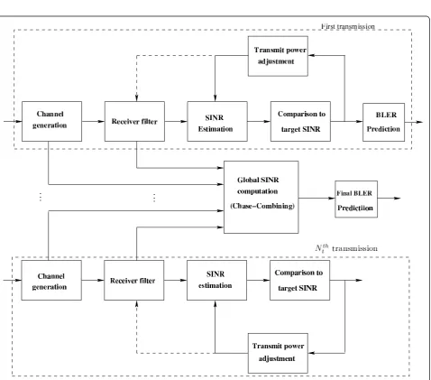
The prediction strategy principle is presented in Figure 3. The Hybrid-ARQ Chase combining approach is con-sidered withNttransmissions. The TPC which is
neces-sary for HSUPA system is also taken into account. It is done separately for each Hybrid-ARQ transmission. The main hypothesis of the prediction method is the Gaus-sian approximation at the receiver filter output. With this assumption, the SINR at the filter output is equiva-lent to that of an AWGN channel. Hence, the HSUPA performance in AWGN channel can be exploited as LUT for performance abstraction in a multipath channel [7]. The abstraction accuracy depends on the SINR esti-mation at the filter output. Hereafter, we derive the ana-lytical SINR expressions for both Rake and LMMSE receivers. Furthermore, an analytical SINR after Hybrid-ARQ Chase combining is given.
3.2. SINR estimation
The receiver filter output corresponding to themth chip is expressed as
zm=wHym
=wH.H.xm+wH.nm
(3:1)
wherewis the vector, of lengthNr(2E+ 1), containing
hermitian operator. Let us introduce a vector Gsuch thatG=wHH= [g0,. . .,gNr(2E)]. Thus, the SINR at the output of the receiver filter per Hybrid-ARQ transmis-sion can be written as
SINR = SF0β
2 0Ecg0
2
Ec
GGH−g02
+w2N0
(3:2)
The vector of the receiver filter coefficients, w depends on the selected detector. Hence, when the rake
receiver is used, this vector is expressed as
wRake=eHH (3:3)
where eis a vector of zero components except the (E
+L)th element which is equal to 1. When the detection is done with an LMMSE detector, the vector containing its coefficients are given by
wLMMSE=
HHH+N0
Ec
I −1
HE+L (3:4)
Figure 2Frame structure of DPCCH control channel. In this figure we present the structure of the uplink DPCCH frame which carries the pilot symbols used for channel estimation purpose.
whereHE+Lis the (E+L)th column of channel matrix
H.
Once the SINR is computed according to (3.2), it is compared to a target SINR, SINRT. The TPC commands
are then generated as follows:
TPCcmd=
0, if SINR>SINRT
1, if SINR<SINR
T (3:5)
wherecmdrefers to command.
After TPC commands generation, the transmit chip power is adjusted (see Figure 3) in response to these com-mands: if TPCcmd=“0”, the transmit power is reduced by δdB which is the power control step size. When TPCcmd=
“1”the transmit power is increased byδdB. This is done in an iterative manner until the target SINR is reached. At the first transmission, after power control, the SINR is also used in Hybrid-ARQ process. Its availability makes it easy to predict the BLER which indicates if a packet is correctly received or erroneous. If a packet is detected to be in error, its retransmission is requested, and the channel matrix and the filter coefficients are saved for Chase com-bining SINR computation.
Let us consider Chase combining scenario with Nt
transmissions. The output of Hybrid-ARQ combiner may be written as
z=
Nt−1
j=0
zj (3:6)
wherezjis the filter output corresponding to the jth
Hybrid-ARQ transmission.
If we introduce a vectorGj=wHHj, Equation (3.6) can
be then expressed in the following vector form
z=
Consequently, the global SINR after the despreading is calculated according to this formula
SINRglobal=
After SINR estimation, the BLER is derived from pre-stored LUTs which summarize the iterative turbo decoding behavior. These LUTs are constructed using Monte-Carlo simulations through an AWGN channel, and are in the form (Ec/N0 in dB, BLER). So, it is
necessary to compute an effective Ec/N0 from the esti-mated SINR. For this, we assume that the SINR at the output of the receiver filter is equivalent to the received
Eb/N0. Thus, the effectiveEc/N0can be calculated as
fol-The BLER is then obtained according to this expres-sion
where f(.) indicates the linear interpolation function which takes the effective(Ec
N0)dBas input and calculates
the corresponding BLER by linear interpolation using AWGN LUT [8].
4. Effect of channel estimation on the performance prediction
When perfect channel knowledgement is not consid-ered, the receiver has to make channel estimation which cannot be done without error. This affects the perfor-mance prediction methodology since the SINR estima-tion is based on the estimated channel coefficients. In this study, channel estimation is performed by extracting the channel state information contained in the known pilot symbols carried by the UMTS control channel DPCCH [9,10]. So, DPCCH despreading is necessary for channel estimation. As in [11], under the hypothesis that the channel estimation error has a Gaussian beha-vior, we can express the estimated channel vector,
ˆ
h= [hˆ0,. . .,hˆL−1], as ˆ
h=h+u, (4:1)
whereuis a vector ofLAWGN samples, each of zero mean, and a variance expressed (see Appendix 1) as
σ2
The SINR at the Rake receiver output is given by
SINRRake(hˆ/h) =
If we denote byHˆ the estimated channel matrix, the vector of LMMSE filter coefficients is written as
Define the vectorGˆ =wˆHLMMSEH. The SINR at the out-put of the LMMSE filter is given by
SINRLMMSE(hˆ/h) = SF0β
Performance prediction process with channel estima-tion is accomplished according to the following steps.
•Step 1. Draw a channel realizationh,
• Step 2. Generate the noisy channel, hˆ such as ˆ
h=h+u, where u is the vector of AWGN noise samples where each has zero mean and the variance expressed in (4.2),
• Step 3. ComputeSINR(hˆ/h)using the formula in (4.3) for the Rake receiver, or (4.5) for the LMMSE detector,
• Step 4. Calculate the mathematical expectation of SINR(hˆ/h),
•Step 5. Perform the TPC process
- CompareSINR(hˆ/h)to the target SINR, SINRT
- Update the transmitted chip energy,Ec, using
TPC command as expressed in (4.6) - Calculate theSINR(hˆ/h)with updatedEc
•Step 6. Predict the BLER using LUTs and the final SINR corresponding to current transmission.
Note that TPC process (Step 5) is repeated until the estimatedSINR(hˆ/h)is close to target SINR. Then, the final value of SINR is used for Hybrid-ARQ Chase com-bining purpose.
To see whether a retransmission of a packet is required or not, the predicted BLER in Step 6 is exploited and compared to a uniform random variable
ϑ, in the following criterion
ACK, if BLER≥ϑ
NACK, elsewhere (4:6)
5. Numerical results
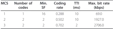
In this section, simulation results are presented to investigate the effect of channel estimation on the FPP technique. First, we describe how the LUTs are built. The FPP is then validated with the HSUPA link simu-lator (LS) according to 3GPP technical specifications [12]. The joint application of Chase combining and transmit power control is also addressed. Finally, simulation results of FPP with channel estimation are presented for HSUPA configurations presented in Table 1.
5.1. Look-up tables
As mentioned above, the LUTs are built using the HSUPA LS with an AWGN channel. The Max-Log-MAP algorithm, with 8 iterations, is considered for decoding the 1/3 rate Turbo encoder. The LUTs sum-marize the HSUPA decoder behavior in terms of BLER as a function of received Ec/N0. Each selected HSUPA
modulation and coding scheme (MCS) needs only one LUT, also called a reference curve, for its performance prediction in a multipath channel.
5.2. Fast performance prediction validation
To see how accurate the FPP simulator is, computer simulations are done for HSUPA transmission. The FPP performance are obtained using the simulator corre-sponding to the structure presented in Figure 3 which consider hybrid-ARQ Chase combining [13,14]. The TPC process is assumed to be inactive. For FPP verifica-tion, it is necessary to run the HSUPA link simulator and FPP simulator with the same assumptions. In the LS, the turbo decoding is performed using the same algorithm and number of iterations as those used for building the LUTs. However, in the FPP simulator, turbo decoding process is not run since its performance is summarized in LUTs.
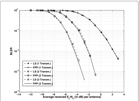
Simulations were done for MCS 2 through a multipath channel which has the same profile as ITU-Pedestrian B Channel with the mobile speed of 3 Km/h. Note that profile is used for all computer simulations in this work. Results of FPP and LS simulator, are shown in Figure 4. It is observed that the FPP simulator is accurate com-pared to the LS for both single transmission and Hybrid-ARQ retransmissions. Moreover, with FPP, a sig-nificant gain, in terms of CPU time is obtained.
5.3. Channel estimation effect on FPP
Having shown the accuracy of FPP simulator, computer simulations are run to assess the impact of noisy chan-nel on this simulator considering Hybrid-ARQ Chase combining and TPC. The HSUPA configuration we adopted in this assessment includes MCS 1 and MCS 3. The number of Hybrid-ARQ transmissions is fixed to 2. The detection is done with a Rake receiver for the first configuration. The second one (MCS 3) is detected with
Table 1 HSUPA modulation and coding schemes
MCS Number of
LMMSE equalizer. As mentioned in 3GPP technical spe-cifications [9], the maximum number of pilot symbols,
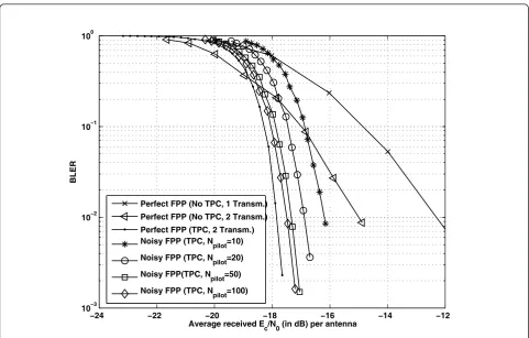
Npilot, is fixed to 150 for MCS 1 and 30 for MCS 3. BLER results of MCS 1 are presented in Figure 5. It is seen that for received Ec/N0 lower than -19 dB, no enhancement is provided by the TPC process when per-fect channel knowledgement is assumed at the receiver end. However, when receivedEc/N0 is up to -19 dB, an important gain is offered. In fact, we observed a gap of 2.5dB when a BLER of 10-2 is reached. If channel esti-mation is taken into consideration, this gain depends on the number of pilot symbols used to estimate the chan-nel coefficients. A great number of pilots results in more accurate estimated channel coefficients. It is also seen that the noisy channel effect is considerable for a small number of pilot symbols. This effect is signifi-cantly reduced after applying TPC.
Figure 6 presents the BLER results of MCS 3 which uses LMMSE equalizer. It is concluded that the system
exhibits poor performance for lowest number of pilot symbols.
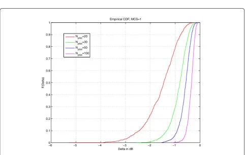
The channel estimation effect, in terms of transmitted pilot symbols, may be seen using the empirical cumula-tive density function (CDF) of parameter Delta which is defined to be the difference between the SINR com-puted assuming perfect channel knowledge and that cal-culated with noisy channel coefficients. Figure 7 shows the CDF of Delta for different numbers of pilot symbols. It is also seen, in terms of CDF that the impact of chan-nel estimation on fast simulator is significantly reduced when increasing the number of pilot symbols.
6. Conclusion
In this article, we have studied the effect of channel esti-mation on the simplified simulation methodology for HSUPA. Transmit power control and Hybrid-ARQ Chase combining have been considered. It has been seen that a noisy channel effect depends on the number
−14 −12 −10 −8 −6 −4 −2 0 2 4
10−4 10−3 10−2 10−1 100
Average received Ec/N0 (in dB) per antenna)
BLER
LS (1 Transm.) FPP (1 Transm.) LS (2 Transm.) FPP (2 Transm.) LS (3 Transm.) FPP (3 Transm.)
of pilot symbols transmitted on the HSUPA control channel. Simulation results have demonstrated that when a sufficient number of these symbols is used, the performance is close to that obtained with the perfect CHACK assumption. Moreover, the application of TPC compensates the performance degradation when a small number of pilot symbols. This has been verified for both Rake and LMMSE receivers.
Appendix 1: DPCCH despreading
For channel coefficients estimation in HSUPA, we have to extract the time multiplexed control channel, DPCCH, from received signal containing the pilot sym-bols. For this, we consider the HSUPA transmission sce-nario presented in Figure 1. The multicode transmitted signal with time multiplexed control channels is expressed as follows
xhsupa(t) =Ec K−1
k=0
sed,k(t)ced,k(t)βed,k·iqed,k
+EcSec(t)Cec(t)βec·iqec
+EcShs(t)Chs(t)βhs·iqhs+
EcSc(t)Cc(t)βc·iqc
(6:1)
After time multiplexing, the multicode signal is sent through a multipath channel which has the well known impulse response given by this expression
hc(t) = L−1
l=0
hlδ(t−τl) (6:2)
The received signal is then expressed as
xhsupa(t) =xhsupa(t)∗hc(t) +n(t)
=Ec L−1
l=0 hl
K−1
k=0
sed,k(t−τl)ced,k(t−τl)βed,k·iqed,k
+EcSecβec·iqec L−1
l=0
hlCec(t−τl)
+Ec L−1
l=0 hl
Shsβhs·iqhsChs(t−τl)
+EcScβc·iqcCc(t−τl)
+n(t)
(6:3)
DPCCH despreading is performed by calculating the inter-correlation between the received multicode signal and the spreading code corresponding to DPCCH
−24 −22 −20 −18 −16 −14 −12
10−3 10−2 10−1 100
Average received Ec/N0 (in dB) per antenna
BLER
Perfect FPP (No TPC, 1 Transm.) Perfect FPP (No TPC, 2 Transm.) Perfect FPP (TPC, 2 Transm.) Noisy FPP (TPC, Npilot=10)
Noisy FPP (TPC, Npilot=20)
Noisy FPP(TPC, Npilot=50)
Noisy FPP (TPC, Npilot=100)
−3 −2.5 −2 −1.5 −1 −0.5 0 0.5 10−3
10−2 10−1 100
Average received Ec/N0(in dB) per antenna
BLER
Perfect CHACK
Imperfect CHACK, Npilot=5 Imperfect CHACK, Npilot=10 Imperfect CHACK, N
pilot=20
Imperfect CHACK, Npilot=30
Figure 6Channel estimation effect on MCS 3 performance using the LMMSE chip equalizer. Figure 6 shows the channel estimation effect on MCS 3 performance. The detection for this configuration is done with LMMSE chip equalizer.
−06 −5 −4 −3 −2 −1 0
0.1 0.2 0.3 0.4 0.5 0.6 0.7 0.8 0.9 1
Delta in dB
F(Delta)
Empirical CDF; MCS=1
Npilot=20
Npilot=30
Npilot=50 Npilot=100
channel. The output of the despreading process is
channel coefficient is estimated by multiplying the despreading output by the transmitted pilot sequence. This is expressed as
˜
Since the additive noise is an AWGN with zero mean (by simulation), its effect on channel estimation can be significantly reduced by taking an average ofh˜lover the
pilot sequence size,Np.
ˆ
Many thanks to our TEX-pert for developing this class file.
Author details
1
Department of Communications Systems, INPT, 2 Av. Allal El Fassi, Madinat Al Irfane, Rabat, Morocco2Lab-STICC, UMR CNRS 3192/Ueb, Signal and Communications Department, Institut Telecom/Telecom Bretagne, Technopôle, Brest-Iroise, CS 83818, 29200 Brest Cedex 3, France3 Orange-Labs, 38-40 rue du générale-Leclerc, F-92792 Issy Moulineaux, Cedex 9, France
Competing interests
The authors declare that they have no competing interests.
Received: 2 June 2011 Accepted: 19 April 2012 Published: 19 April 2012
References
1. M Et tolba, S Saoudi, R Visoz, TA Idir, Chip-level LMMSE based Hybrid-ARQ Chase combining for HSUPA, inIEEE VTC-Spring, vol. 3. Barcelona, Spain, pp. 1–5 (2009)
2. J Kim, A Ashikhmin, AJ van Wijngaarden, E Sljanin, N Gopalakrishman,On Efficient Link Error Prediction based on Convex Metrics, vol. 6. IEEE VTC-Fall, Los Angeles, pp. 4190–4194 (2004)
3. TSG-RAN WG1 #35,Link Error Prediction for E-DCH, (Lucent Technologies, Lisbon, 2003)
4. M Et tolba, M Eljamai, S Saoudi, R Visoz, Link performance prediction for HSUPA in a multipath channel, inACM IWCMC’09, vol. 2. Leipzig, Germany, pp. 859–863 (2009)
5. M Lalam, R Visoz, AO Berthet, Fast performance prediction of iterative MMSE-IC receivers in MU-MIMO CDMA systems, inIEEE VTC-Fall, vol. 6. Anchorage, Alaska, pp. 1–5 (2009)
6. I Stupia, F Gianneti, V Lottici, L Vandendorpe, A novel link performance prediction method for coded MIMO-OFDM systems, inIEEE WCNC, vol. 1. Budapest, pp. 1–5 (2009)
7. A Das, A Sampath, Link error prediction for wireless system simulations, in
IEEE WCNC, vol. 1. Atlanta, Georgia USA, pp. 507–512 (2004) 8. R Ratasuk, A Ghosh, T Brown, R Love, W Xiao, Predicting link level
performance for enhanced uplink, inIEEE VTC-Fall, vol. 6. Los Angeles, pp. 4185–4189 (2004)
9. 3GPP TS 25.213,Spreading and Modulation (FDD)(May 2007). Version 7.2.0
10. H Holma, A Toskala,HSDPA/HSUPA for UMTS, (John Wiley and Sons Ltd, The Atium Southern Gate, Chichester, West Sussex PO 19 8SQ, England, 2006) 11. R Visoz, AO Berthet, M Lalam, A novel fast semi-analytical performance
prediction method for iterative MMSE-IC multiuser MIMO joint decoding, in
IEEE GLOBECOM, vol. 55. New Orleans, LA, USA, pp. 1–5 (2008)
12. S Parkvall, J Paisa, J Torsner, M Sagfors, P Malm, WCDMA enhanced uplink -principles and basic operation, inIEEE VTC-Spring, vol. 3. Stockholm, Sweden, pp. 1411–1415 (2005)
13. D Chase, Code Combining-a maximum-likelihood decoding approach for combining an arbitrary number of noisy packets. IEEE Trans Commun.
XXXIII, 385–393 (1985)
14. M Bertinelli, E Malkamaki, Hybrid-ARQ for WCDMA enhanced uplink: link level performance in SHO, inIEEE PIMRC, vol. 4. Barcelona, Spain, pp. 2856–2860 (2004)
doi:10.1186/1687-1499-2012-148
Cite this article as:Et-tolbaet al.:Fast performance prediction of power
controlled HSUPA with channel estimation.EURASIP Journal on Wireless
Communications and Networking20122012:148.
Submit your manuscript to a
journal and benefi t from:
7Convenient online submission
7Rigorous peer review
7Immediate publication on acceptance
7Open access: articles freely available online
7High visibility within the fi eld
7Retaining the copyright to your article