A terahertz (THz) radar provides the possibility of higher precision imaging due to the wider bandwidth. A summary of a THz imaging radar system is presented with emphasis on THz radar component design, system design, and detective imaging. In this article, we introduce a linear frequency-modulated continuous wave (LFMCW) radar system with a 4.8-GHz bandwidth and theoretical resolution of 3.125 cm. The heterodyne RF receiver structure is applied to the system to reduce the sampling rate. A non-linear correction method is applied to compensate the range backscatter signal. With the presented LFMCW radar system, high-resolution images (3.5 cm × 3.5 cm) are achieved using the ISAR imaging technique. The experiments performed on the real LFMCW radar data have shown the capability of high-resolution imaging.
Keywords:Terahertz; LFMCW radar; Error correction; ISAR
1. Introduction
A terahertz frequency band is a very important research and valuable undeveloped frequency resource, which es-pecially has a great potential for the development of a high-resolution imaging radar. Compared to the trad-itional microwave radar, the advantages of a terahertz radar system are as follows: Firstly, the shorter wave-length is favorable toward providing a wider bandwidth, which could benefit the higher precision of imaging. Sec-ondly, the narrow antenna beam in the terahertz band could not only obtain higher antenna gain in radar LOS, improving the ability of multi-target discrimination and recognition, but also reduce the opportunity of main lobe jamming [1-3]. The terahertz radar detection sys-tem is an important direction of terahertz technology domestic and overseas [4].
A linear frequency-modulated continuous wave (LFMCW) radar has advantages of high range resolution, low transmit power, high receiver sensitivity, simple structure, etc. [5,6]. There is no distance blind area, better anti-stealth ability than a pulse radar, background clutter, and anti-jamming characteristics, and it is particularly suitable for near-range applications [7]. A terahertz wave has great
bandwidth itself, so making use of the LFMCW radar struc-ture can obtain a very high range resolution; the emission power of the terahertz wave is still very low at present, and the LFMCW radar has lower emission power than the pulse radar, so using a LFMCW radar system can reduce the transmitter power requirements. In consideration of the great bandwidth of terahertz waves and the high range reso-lution of the LFMCW radar, the terahertz LFMCW radar can obtain high range resolution [8,9].
Currently, the international research institutions with
terahertz radar experimental systems are the Jet
Propulsion Laboratory (JPL) (0.6 THz radar imaging system) [10] and the German Institute of Applied
Science (Forschungsgesellschaft für Angewandte
Naturwissenschaften, FGAN) High Frequency Physics and Radar Techniques (FHR) Laboratory (0.22 THz COBRA inverse synthetic aperture radar (ISAR) imaging system) [11]. In 2006, RJ Dengler and KB Cooper et al. of JPL have successfully developed the first high-resolution terahertz imaging system with a 2-cm range resolution; this system introduced FMCW radar technol-ogy into the imaging system, processed the waveform distortion compensation by software, and obtained a 2-cm range resolution (internal 4 m) [12]. In 2008, KB Cooper et al. who came up with a 0.6 THz radar im-aging system have successfully developed a 0.58 THz high-resolution three-dimensional imaging radar system * Correspondence:[email protected]
School of Electronic Engineering, University of Electronic Science and Technology of China, Chengdu 611731, China
based on the 0.6 THz radar imaging system [13]. The im-aging system used in ISAR imim-aging can obtain subcen-timeter resolution. In 2007, Essen and Wahlen et al. of the German Institute of Applied Science (FGAN) High Frequency Physics and Radar Technology (FHR) Laboratory have successfully developed a 220-GHz ter-ahertz imaging radar system COBRA-220 [14]. The sys-tem is also based on a LFMCW radar syssys-tem, in which the FM bandwidth is 8 GHz, successfully achieving the 1.8-cm range resolution in a 200-m distance.
In this paper, we present an overview of the THz im-aging radar technology. The radar is currently a portable laboratory prototype system operating in a LFMCW mode over a 4.8-GHz bandwidth in the University of Electronic Science and Technology of China (UESTC). The remainder of this paper is organized as follows. Section 2 describes the LFMCW signal model. In Section 3, a dual-source structure model for an inter-mediate frequency receiver in the THz radar is devel-oped. This is followed by Section 4 in which a detailed analysis of the signal and the correcting method are pre-sented. In Section 5, the experiment results for the LMFCW THz radar are shown. We conclude the paper in Section 6.
2. LFMCW signal analysis
In ideal conditions, the LFMCW radar's transmitting and receiving signal frequency can be shown in the Figure 1. The transmitting signal is expressed as
Stð Þ ¼t exp 2πf0tþπK t2þθ0
;0≤t≤T ð1Þ
wheref0is the carrier frequency,tis the time variable,K
is the frequency modulation slope,T is the duration of
the signal, andθ0is the initial phase.
Ifτis the time delay of a stationary target at the range R, then the received signal can be expressed as
Srð Þ ¼t Stðt−τÞ
In order to reduce the sampling rate, the beat signal can be obtained in intermediate frequency after mixing the transmitting signal and the received echo signal.
Sbð Þ ¼t Stð Þ t Srð Þt
¼ exp 2f πf0τþ2πKτt−πKτ2g;τ≤t≤T
ð3Þ
The beat frequency can be calculated which is the de-rivative of the beat signal phase.
fbð Þ ¼t
It is obvious that the beat frequency is a fixed value, only related to the distance and frequency modulation slope. Then, the range of target is expressed as
R¼fbc
2K ¼
cT
2Bfb ð5Þ
So the frequency of the beat signal is the identification to the target range. After sampling was carried out on the beat signal of the LFMCW radar, the beat frequency signal's frequency spectrum can be obtained by discrete
Figure 1Time-frequency of transmitting signal (ft), receiving signal (fr), and beat signal (Δf(t)).
Fourier transform (DFT). In the spectrum, the peak lines are corresponding to the beat frequency and static target's range.
3. Intermediate frequency receiver
Figure 2 can show the conventional LFMCW radar's system structure from which the signal model is analyzed in previ-ous chapters. The power of the signal source is limited by the apparatus in the THz wave band. The single frequency source has difficulty transmitting and mixing at the same time. If two independent frequency sources are employed in a radar system, it may lead to the issue of phase out of sync.
The‘non-coherent dual-source implementing coherence’ way is applied in the THz LFMCW radar system. The co-herent system structure can be shown in Figure 3. Mixing twice needs to be done in order to realize the coherent sys-tem. The intermediate frequency receiver is designed after the first mixing of the received THz band frequency signal. The second mixing, I/Q demodulation, signal correction, and some other processing are involved in the intermedi-ate frequency receiver.
Signal sources S1 and S2, two low-frequency linear
frequency modulation signals, are used to produce the transmitting signal and the local oscillator (LO) signal, respectively. They can be respectively represented as
S1ð Þ ¼t A1exp 2f πfC1tþπKS1t2þϕ1g
S2ð Þ ¼t A2exp 2f πfC2tþπKS2t2þϕ2g
ð6Þ
where fc1and fc2are the carrier frequency, t is the time
variable,Ks1andKs2are the frequency modulation slope,
andϕ1andϕ2are the initial phase.
The transmitting signal can be generated from the source
S1 by means of × 12 frequency multiplication (×2 twice
and × 3 once), band-pass filtering, and amplification. Then, it can be represented as
STð Þ ¼t ATexp 2π⋅12fC1tþπ⋅12K0t2þ12ϕ1
ð7Þ
whereATis the signal amplitude. It is supposed thatR(t) is the range of target andτ(t) = 2R(t)/cis the echo signal time delay. The received echo signal can be expressed as
(a)
Frequncy/Hz x10 5
SRð Þ ¼t K ATexp
2π⋅12fC1ðt−τð Þt Þ þπ⋅12K0ðt−τð Þt Þ2þ12ϕ1
ð8Þ
The LO signal in the THz band can come from the sourceS2by the same procedure as the transmitting
sig-nal. It can be expressed as
SLO1ð Þ ¼t ALO1exp 2π⋅12fC2tþπ⋅12K0t2þ12ϕ2
ð9Þ
where ALO1 is the amplitude of the LO signal. The first
mixing is realized between the received echo signal (SR(t)) and the LO signal (SLO1(t)). So the obtained intermediate
signal is
SIFð Þ ¼t AIFexp
2π12ðfC2−fC1Þtþ12fC1τð Þt þμτt tð Þ−μτð Þt 2=2þ12Δϕ ð10Þ
whereAIFis the amplitude of the intermediate frequency
signal, μ= 12K0is the frequency modulation slope, and
Δϕ=ϕ2−ϕ1is the difference of initial phases.
The other LO signal is acquired through the following procedure: mixingS1andS2, ×12 frequency multiplication,
amplifying, and filtering. It can be represented as
SLOð Þ ¼t ALOexp 2f π⋅12ðfC2−fC1Þtþ12Δϕg ð11Þ
In the end, the result of mixing intermediate frequency signalSIF(t) and LO signalSLO(t) is
SBð Þ ¼t SIFð Þ t SLOð Þt
¼ABexp 2π μτð Þt tþ12fC1τð Þt −μτð Þt 2=
2
ð12Þ
The results show that the initial phase difference is off-set through taking advantage of the dual-source system structure. The results are consistent with the traditional single-source LFMCW radar system structure. Thereby, the problem about the dual-source's non-sync can be solved effectively.
4. Error analysis and correction
In the FMCW radar, the range information of the target can be obtained from the spectral content of the final
signal. The range resolution of a FMCW radar depends only on the bandwidth of the transmitting signal. The range resolution is the minimum distance that two targets
(b)
0 100 200 300 400 500 600 700 800 900 1000 -500
0 500 1000 1500
2000 imaginary part of sampled data
time(us)
Amplitude
100 200 300 400 500 600 700 800 900 1000 -4500
-4000 -3500 -3000 -2500 -2000 -1500 -1000 -500 0 500
real part of sampled data
time(us)
Amplitude
-200 -150 -100 -50 0 50 100 150 200 -70
-60 -50 -40 -30 -20 -10 0
10 spectrum of the noise floor
frequency(Hz)
Amplitude(DB)
-200 -150 -100 -50 0 50 100 150 200 -80
-70 -60 -50 -40 -30 -20 -10 0
10 Spectrum of sampled data
frequency(Hz)
Amplitude(DB)
-200 -150 -100 -50 0 50 100 150 200 -70
-60 -50 -40 -30 -20 -10 0 10
Spectrum of the target
frequency(Hz)
Amplitude(DB)
(c)
(d)
(e)
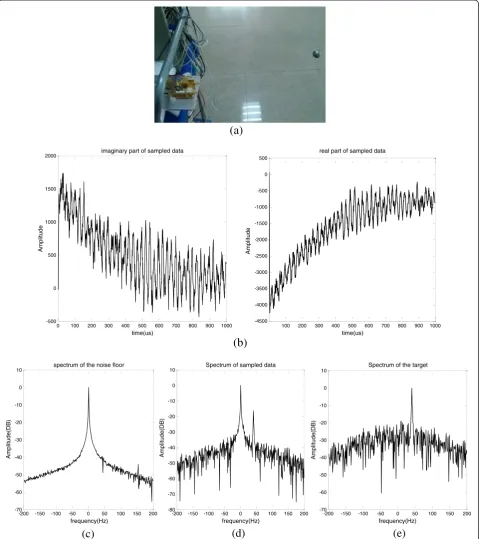
Figure 6Metal ball range detection experiment. (a)Single metal ball testing scene.(b)The sampled data (real and imaginary part).
can be separated along the radar's line of sight before they are indistinguishable.
If the radar tone is measured for the time Δt, the
Fourier-limited single-target spectral width will beδfbmin=
1/Δt. In according to formula (5), the minimum range reso-lution can become
δrmin¼ c 2K0δfbmin
¼ c
2K0 1
Δt¼ c
2ΔF ð13Þ
It means that the range resolution only depends on the total swept bandwidth. The inverse relationship between the range resolution and bandwidth is similar to the ordin-ary pulsed radar. With a bandwidth of 4.8 GHz, the theor-etical range resolution of our THz radar is 3.1 cm; however, this theoretical value is only achieved if unwanted modulation in the LFM waveform is compensated for.
Now the amplitude and phase error would be discussed in detail, which will deteriorate severely the range reso-lution. Suppose a modulation in the phase or amplitude of the LFM waveform can be modeled as perturbationsφ(t) andA(t) in the transmitted and LO signals which are not flat in the total bandwidth. Besides, a direct current or low-frequency component SL(t) will result owing to the
sampling in our practical THz radar system. Thus, formula (12) becomes
SBð Þ ¼t ABexp
2π μτtþ12fC1τð Þt −μτ2=2 ⋅A tð Þ⋅expfΔφð Þt g þS
Lð Þt
ð14Þ
whereA(t) =ALO(t)⋅AT(t−τ) andΔφ(t) =φLO(t)−φT(t−τ). In order to compensate for this degradation, some steps are taken in signal processing.
(a)
(b)
-100 -80 -60 -40 -20 0 20 40 60 80 100 -40
-35 -30 -25 -20 -15 -10 -5 0 5
Spectrum
frequency(Hz)
Amplitude(DB)
Figure 7Testing of three metal balls. (a)Testing scene of three metal balls.(b)The spectrum of sampled data for range detection.
Cross range(m)
Range(m)
-0.5 -0.4 -0.3 -0.2 -0.1 0 0.1 0.2 0.3 0.4 0.5 1.3
1.4 1.5 1.6 1.7 1.8 1.9 2 2.1 2.2 2.3
Firstly, a smoothing low-pass filter is applied to remove the low-frequency componentSL(t).
Secondly, a calibration signal is acquired as a reference using a typical bright target at a range R0 in the radar's operating range, and the referent IF signal is recorded.
Srefð Þ ¼t exp 2f π μτð 0tÞg⋅AR0ð Þt ⋅expfΔφR0ð Þt g ð15Þ
Finally, some other subsequent signals are divided by this calibration reference before spectral analysis, so the detected IF signal will be modified as
SBð Þ ¼t SBð Þt ⋅expf−ΔφR0ð Þt g=AR0ð Þt ð16Þ
The signal spectrum will also be shifted by a known amount Δf=μτ0= 2μR0/c which can be added back
eas-ily. The resolution can improve significantly as long as the compensated amplitude approaches unity and the phase approaches zero.
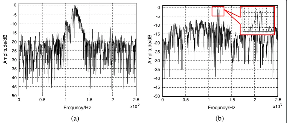
The raw range spectrum of the two point-like targets is shown in Figure 4a. The main lobe of each target is severely broadened by the chirp waveform non-linearity, and we hardly recognize these two targets from this spectrogram. In contrast, Figure 4b shows the same measurement where the signal is first divided by a previ-ously acquired calibration waveform prior to calculating the range spectrum. After compensation, the broadened peaks become now much narrower. This process cor-rectly removes the non-linearity effects and improves the range resolution of the radar system.
From the above formula derivation, we know that this method can perfectly compensate the range spectrum of the target which is located in the same distance with the reference target. Practically, calibrating using the target at R=R0results in excellent non-linearity compensation
over the entire range ofR0± 1, and a high resolution can
also be obtained.
5. Experimental results
As shown in Figure 5, the LFMCW radar prototyping system working in the THz waveband has been devel-oped in the Radar Imaging Laboratory of UESTC. The transmitting signal bandwidth is 4.8 GHz.
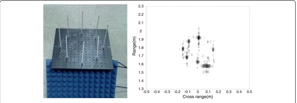
In order to validate the performances of our radar sys-tem, some experiments have been conducted, and the results will be shown as follows. Figure 6 shows the ex-periment results of testing for metal ball range detection with a range of 1.25 m, and detection of three metal balls can been seen in Figure 7. Finally, eight metal rods are arrayed in the platform which can rotate at a con-stant speed controlled by a servos system. Their image can be obtained by using an ISAR imaging method, as shown in Figure 8.
To verify the imaging performance of the non-linearity compensation, another experiment is performed, and the turntable system is used. The imaging results are shown in Figure 9. When the radar transmits the broadband signals, three metal spheres placed on the turntable are rotating at a constant speed. To achieve the same reso-lution in azimuth dimension, we can adjust the accumu-lating azimuth angle. In this experiment, this angle is 1.5°. As shown in Figure 9a, the accurate locations of the three spheres are not determined and the images of these spheres in range dimension are broadened. After compensation, the locations of the three spheres are cor-rected very well, as shown in Figure 9b.
6. Conclusions
It is feasible to use the LMFCW radar in THz waveband to obtain high range resolution and high-quality images. Some measures taken for correcting the signal error are valid in the intermediate frequency receiver to optimize the radar's range resolution. The radar's system structure low-noise LMF source can do the trick. In short, the THz LFMCW radar is an effective tool for range detec-tion and imaging.
(a)
(b)
Competing interests
The authors declare that they have no competing interests.
Received: 29 July 2013 Accepted: 14 November 2013 Published: 17 January 2014
References
1. J Li, YM Pi, Micro-doppler signature feature analysis in terahertz band. J. Infr. Mill. Terahertz. Waves.31(3), 319–328 (2010)
2. JA Hejase, EJ Rothwell, P Chahal, A multiple angle method for THz time-domain material characterization. IEEE. Transac. Terahertz. Sci. Technol.
3(5), 656–665 (2013)
3. KB Cooper, RJ Dengler, N Llombart, B Thomas, G Chattopadhyay, PH Siegel: THz imaging radar for standoff personnel screening. IEEE. Trans. THz. Sci. Technol.1(1), 169–182 (2011)
4. J Ding, M Kahl, O Loffeld, P Haring Bolívar, THz 3-D image formation using SAR techniques: simulation, processing and experimental results. IEEE. Transac. Terahertz. Sci. Technol.3(5), 606–616 (2013)
5. J Moll, P Schöps, V Krozer, Towards three-dimensional millimeter-wave radar with the bistatic fast-factorized back-projection algorithm—potential and limitations. IEEE. Transac. Terahertz. Sci. Technol.2(4), 432–440 (2012) 6. J Feng, Z Cao, Y Pi, Multiphase SAR image segmentation with G0 statistical
model based active contours. IEEE. Trans. Geosci. Remote. Sens.
51(2), 4190–4199 (2013)
7. F Friederich, W von Spiegel, M Bauer, F Meng, MD Thomson, S Boppel, A Lisauskas, B Hils, V Krozer, A Keil, T Loffler, R Henneberger, AK Huhn, G Spickermann, PH Bolivar, HG Roskos: THz active imaging systems with real-time capabilities. IEEE. Trans. Terahertz. Technol.1(1), 183–200 (2011) 8. M Pätzold, M Kahl, TA Keil, T Löffler, PH Bolívar, A Kolb, Simulation and
data-processing framework for hybrid synthetic aperture THz systems including THz-scattering. IEEE. Transac. Terahertz. Sci. Technol.
3(5), 625–634 (2013)
9. P Meta, LP Hoogeboom, Ligthart, Range non-linearities correction in FMCW SAR, inProc. IGARSS(Denver, CO, 2006), pp. 403–406
10. RJ Dengler, F Maiwald, PH Siegel, A compact 600 GHz electronically tunable vector measurement system for submillimeter wave imaging, inIEEE MTT-S Int Digest(San Francisco, 2006), pp. 1923–1926
11. H Essen, A Wahlen, R Sommer, W Johannes, R Brauns, M Schlechtweg, A Tessmann, High-bandwidth 220 GHz experimental radar. Electron. Lett.
43(20), 1114–1116 (2007)
12. RJ Dengler, KB Cooper, G Chattopadhyay, I Mehdi, E Schlecht, A Skalare, C Chen, PH Siegel, 600 GHz imaging radar with 2cm range resolution, in
IEEE MTT-S Int Digest(Honolulu, 2007), pp. 137–1374
13. KB Cooper, RJ Dengler, G Chattopadhyay, E Schlecht, J Gill, A Skalare, I Mehdi, PH Siegel, A high-resolution imaging radar at 580 GHz. IEEE. Micro. Wire. Comp. Lett.18(1), 64–66 (2008)
14. H Essen, S Stanko, R Sommer, A Wahlen, R Brauns, J Wilcke, W Johannes, A Tessmann, M Schlechtweg, A high performance 200-GHz broadband experimental radar. IEEE. 33rd. Int. Conf. Infr. Mill. Terahertz. Waves. IRMMW-THz.2, 527–528 (2008)
doi:10.1186/1687-1499-2014-10
Cite this article as:Yao and Pi:Terahertz active imaging radar: preprocessing and experiment results.EURASIP Journal on Wireless
Communications and Networking20142014:10.
Submit your manuscript to a
journal and benefi t from:
7Convenient online submission 7Rigorous peer review
7Immediate publication on acceptance 7Open access: articles freely available online 7High visibility within the fi eld
7Retaining the copyright to your article