DESIGN AND ANALYSIS OF CIRCLEHEAD SHAPE MICROSTRIP PATCH
ANTENNA
Renuka Baban Singh
1, Er.Nitin Agarwal
21
M Tech Research Scholar P G Department of ECE, RBS Engineering Technical Campus, Bichpuri Agra,U.P.,India
2P G Department of ECE, RBS Engineering Technical Campus, Bichpuri Agra,U.P.,India
---***---
Abstract -
Microstrip patch antennas are increasing inpopularity and get more important these days. This is mostly due to their versatility in terms of possible geometries that makes them applicable for many different situations. The light weight construction and the suitability for integration with microwave integrated circuits are two more of their numerous advantages. Additionally the simplicity of the structures makes this type of antennas suitable for low cost manufacturing. And this is also one key feature of microstrip patch antennas are used in mobile communications applications.
Thus the size reduction and bandwidth enhancement are becoming major design considerations for practical application of microstrip antennas. The purpose of this paper is to design a high bandwidth microstrip patch antenna and to compare with the former patch antennas and then proposed the better one. In this research work, we have designed the CIRCLEHEAD-shaped slotted patch antenna. Here bandwidth is obtained 40% of the center frequency which is the extremely large than the parasitic patch antenna. Microstrip Patch Antennas (MPA) are extremely attractive candidates for use in many applications due to their interesting features such as low cost, light weight, thin profile and conformability. A 3D field solver is used to simulate the performance of the proposed antenna by inputting the sizes of the physical structure. Coaxial probe feeding technique is used to feed the antenna. Zeland IE3D ver14 software is used to design and simulate the proposed patch antenna.
Key Words:
Rectangular microstrip antenna, coaxial
probe feeding, slotted patch antenna, CircleHead shape
patch antenna.
1. INTRODUCTION
Communication can be broadly defined as the transfer of information from one point to another. A communication system is usually required when the information is to be conveyed over a distance. The transfer of information within the communication system is commonly achieved by superimposing or modulating the information onto an electromagnetic wave which acts as a carrier for the information signal. At the required destination, the modulated carrier is then received and the original information signal can be recovered by demodulation. Over the years, sophisticated techniques have been developed for this process using electromagnetic carrier waves operating at radio frequencies as well as microwave and millimeter wave frequencies. In today’s modern communication industry, antennas are the most important components required to create a communication link. Through the years, microstrip patch antenna structures are the most common option used to realize millimeter wave monolithic integrated circuits for microwave, radar and communication purposes. The shape and operating mode of the patch are selected, designs become very versatile in terms of operating frequency, polarization, pattern and impedance [6].
1.1 Micro strip Patch Antenna
Microstrip Patch Antennas (MPA) is extremely attractive candidates for use in many applications due to their interesting features such as low cost, light weight, thin profile and conformability. On the other side, the greatest disadvantage of MPA is its low bandwidth which can be as low as 1%.
These antennas can be integrated with printed strip-line feed networks and active devices.
apex factor contributed for the recent advances of microstrip antennas. Conventional antennas being sizeable and high-cost part of an electronic system, micro strip antennas based on photolithographic technology are considered as quantum leap. [1]
1.2 Structure
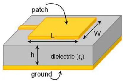
A Microstrip Patch antenna consists of a radiating patch on one side of a dielectric substrate which has a ground plane on the other side in its most fundamental form as shown in Figure 1. The patch is generally made of conducting material such as copper or gold and can take any possible shape. The radiating patch and the feed lines are usually photo etched on the dielectric substrate. [6]
2. ANALYSIS OF MICRO STRIP PATCH ANTENNA
Resonance Frequency: The resonance frequency
depends on the patch size, cavity dimensions, and the filling material dielectric constant. It is expressed as follows;
Where fr is the resonance frequency at which the rectangular microstrip antenna is to be designed. The radiating edge W, patch width is usually kept such that it lies within
the range L<W>2L for efficient radiation.
The ratio W/L= 1.5 gives good performance according to the side lobe appearances. [5]
By using the above equations we can find the values of actual length of the patch as:
where eff is the effective dielectric constant and ∆l is the line extension which is given as
3. RECTANGULAR MICROSTRIP ANTENNA DESIGN
PARAMETERS
In this paper several parameters of Rectangular Microstrip patch Antenna resonating at frequency 1.09GHZ have been investigated using Zealand Ie3d ver14 software. The geometry of patch antenna is shown in figure-1. The design specifications for patch antenna are:
3.1 SIMULATION RESULT:
Figure 2: Rectangular microstrip patch antenna resonating at 1.09 GHZ.
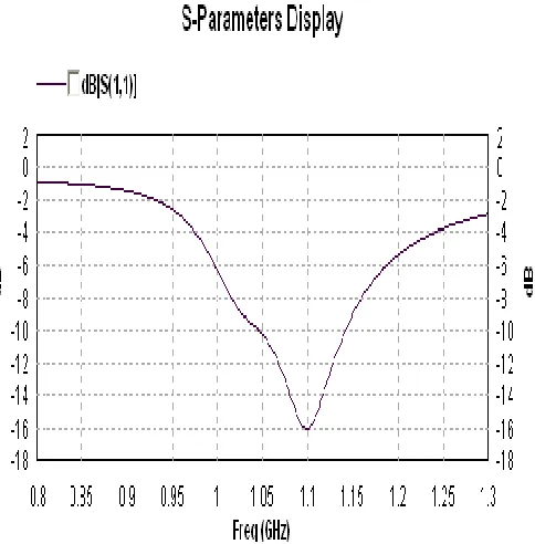
Figure 3: S parameter Display of rectangular microstrip
patch antenna
Figure 4: VSWR Display of rectangular microstrip patch antenna.
In that figure, the operating frequency is 10 MHZ from 1.04 GHz to 1.14 GHz, where VSWR≤2 is. The resonance frequency of that region is 1.09 GHz where maximum return loss -16.00dB.
Figure 6: Current distribution
4. CIRCLEHEAD-SHAPE SLOTTED ANTENNA
The base of CircleHead shaped antenna structure designed is a simple rectangular microstrip patch antenna. The antenna structure is designed by cutting two rectangular slots in the rectangular microstrip patch antenna. The designed antenna structure along with its dimensions is shown in fig 7. The design parameters are same as in case rectangular microstrip patch antenna.
Figure 7: CircleHead shape slotted Microstrip patch Antenna.
4.1 SIMULATION RESULTS :
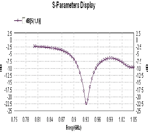
Figure 8: S parameter Display of CircleHead shape slotted
microstrip patch antenna.
In figure 8, 9 the operating frequency is 46 MHZ from 0.911 GHz to 0.957 GHz, where VSWR≤2 is. The resonance frequency of that region is 4.607 GHz where maximum return loss -22.71dB.
Figure 9: VSWR Display of CircleHead shape slotted
Figure 10: Smith chart
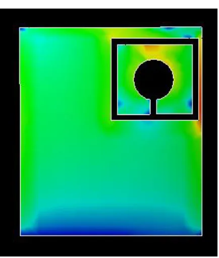
Figure 11: Current distribution of CircleHead shape slotted microstrip patch antenna.
5. RESULT COMPARISION
Table 1: Shows result comparion between rectangular
microstrip patch antenna and CircleHead shape slotted microstrip patch antenna.
Rectangular antenna
CircleHead shape antenna
Resonating frequency
1.09 GHZ 0.93 GHZ
Max Return loss -16.00 dB -22.71 dB
Z parameter 66.68 Ohm 57.76 Ohm
Starting frequency
1.04 GHZ 0.911 GHZ
End frequency 1.14 GHZ 0.957 GHZ
Bandwidth 10 MHZ 46 MHZ
5.1 Simulation Result discussion
6. DESIGNED RECTANGULAR MICROSTRIP
ANTENN HARDWARE
Figure 12: Rectangular microstrip patch antenna resonating at 1.09 GHZ.
7. DESIGNED S SHAPE SLOTTED
ANTENNA HARDWARE
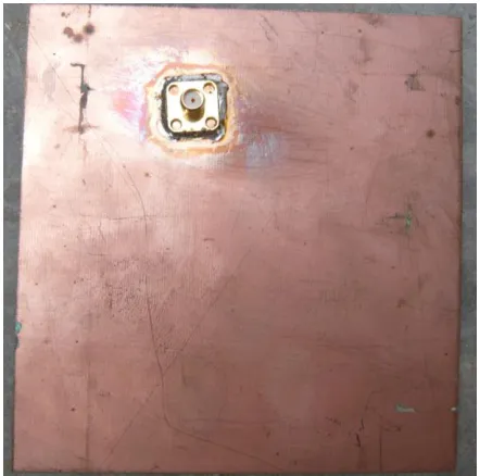
Figure 13: CircleHead shape slotted Microstrip Patch
Antenna.
7.1 MEASURED RESULTS
Figure 14: S parameter Display of CircleHead shape slotted
microstrip patch antenna.
Figure15: Connection of CircleHead MSA through SWR
8. RESULT COMPARISON
Table2: Shows comparison between simulated and tested
results.
Bandwidth
46MHZ
18MHZ
8.1 Simulation Result Discussion
Spectrum Analyser (SA) whose Range of measurement of frequency is 9 KHZ To 3 GHZ was chosen to simulate the Antenna hardware shown in the Figure 12 and 13. The S-parameter was obtained from simulation. The simulated result of CircleHead shape Microstrip Patch Antenna Structure are shown in figure 14. At 1.14 GHz frequency simulated CircleHead Microstrip Patch Antenna alone exhibits the Return Loss of -11.99 dB and Bandwidth about 18 MHz while when it is incorporated with was achieved.
9. CONCLUSION
It always has been the paramount matter of concern to put vigorous attempts to vanquish almost all the limitations of conventional microstrip patch antenna characteristics, which is depicted clearly in this paper and could be understood vividly. Few evident adverse and critical issues like broad banding using slotting technique are taken care in this research work. In spite of that, handy and proficient solutions are now outnumbered and few in number and
encounter many other problems and complications like
distortion of radiation patterns, reduction of gain, complexity of structure etc. Hence, more distant research is earnestly needed in this area of research work.
Finally the following conclusion is came out in our research work:
• In our project we studied different aspects related to microstrip antenna and we have made a microstrip antenna at 1.14 GHz.
• Thus we can say that we have obtained our aim successfully.
10. REFERENCES
[1] A. A. Abdelaziz of Department of Electronics and Communications Faculty of Engineering Misr University for Science and Technology, paper on “Bandwidth Enhancement of Microstrip Antenna”, 2006
[2] Ajay Singh and S. C. Gupta of Dehradun Institute of Technology, Dehradun (India), “Review and Survey of Broadband Microstrip Patch Antennas”, 2012
[3] C.A. Balanis, “Antenna Theory, Analysis and Design,” John Wiley &Sons, New York, 1997.
[4] C. Vishnu Vardhana Reddy, Rahul Rana, of NIT Rourkela, “Design Of Linearly Polarized Rectangular Microstrip patch Antenna sing IE3d/pso” Thesis, 2009.
[5] Global Journal of Research
Engineering Volume 11 Issue 2 Version 1.0 March 2011 ISSN 0975-58
[6] Ray, K. P, “Broadband Microstrip Antennas”, Artech House antennas and propagation library, 2003.
[7] R.Garg, P.Bhartia, I.Bahl, and A.Ittipiboon, Microstrip Antenna Design Handbook Antennas, John Wiley, 1997 Combined with a Ring Antenna for Triple Band Operation in its”, 2013
[8] Roshni Chaudhari, Samreen and S.B.Khant of Electronics and Communication Department, A.D.Patel Institute of Technology, Gujarat, “Bandwidth Enhancement with Proximity Coupled Stacked Circular Patch Configuration with Defected Ground Structures for WLAN Applications”, 2013
[9] Rajesh Kumar Vishwakarma, Sanjay Tiwari of School of Studies in Electronics, Pt. Ravishankar Shukla University, Raipur, Chhattisgarh, ” Experimental Study of Stacked Rectangular Microstrip Antenna for Dual-Band”, 2010 [10] Rushit D Trivedi, Research Scholar, JJTU University, Dist. Jhunjhunu, Rajasthan and Dr. Vedvyas Dwivedi, Director and Principal Nobel Engineering College, Junagadh, Gujarat India, ” Stacked Microstrip Patch Antenna: Gain and Bandwidth Improvement, Effect of patch rotation”.
BIOGRAPHIES
Renuka Baban Singh
1M.Tech reaserch scholar,P G Department of ECE,RBS Technical Campus,Bichpuri,Agra. B.Tech. in ENTC (2000-04)From North Maharashtra University,
Maharashtra. 4 years of working experience in Analysis,
Development and
Implementation of Application in Java from CDAC Noida.
Er.Nitin
Agarwal2 is workingas an Asst Prof in P G