Radioactive wastes and disposal options
Bernhard Kienzler(∗) andHorst Geckeis
Institute for Nuclear Waste Disposal (INE) Karlsruhe Institute of Technology (KIT) Hermann-von-Helmholtz Platz 1, 76344 Eggenstein-Leopoldshafen, Germany
Summary.— This paper provides for a summary of facts which are indispensable for nuclear waste disposal. Information is presented on types of radioactive wastes and the origin, the waste treatment procedures and some characteristics of the waste forms. Finally the various host rocks and the international disposal concepts are discussed and the procedures for safety analyses are shortly described.
1. – Introduction
In 2016, 450 nuclear power plant units with an installed electric net capacity of about 392 GWelectricwere in operation worldwide. Additional 60 plants with an installed capac-ity of 60 GW were under construction in 16 countries (https://www.euronuclear.org/
info/encyclopedia/n/nuclear-power-plant-world-wide.htm June 2017). In
Eu-rope, France has 58 units in operation, producing 63 GWel. The efficiency of a nuclear power plant is in the range of 35%, and the average annual availability is about 80%. A combined gas-steam power plant has an efficiency of about 60%. Nevertheless, the nuclear power plants in France save annually the emission of 130 million metric tons of
(∗) E-mail:[email protected]
CO2 in comparison with the production by combined gas-steam power plant or about 280 million metric tons of CO2 produced by lignite fired power plants (data taken from https://www.eia.gov/tools/faqs/faq.php?id=73&t=11, June 2017). For this reason, nuclear power plays still an important role in preventing CO2 emissions. However, the energy production by nuclear fission produces radioactive wastes. The mass and volume of the nuclear waste is relatively small but due to its high radiotoxicity it needs to be treated and disposed safely for very long periods of times.
2. – Origin, type and amount of radioactive wastes
Today, most of the nuclear power plant reactors are pressure water (PWR) or boiling water (BWR) reactors. Both reactor types are light-water nuclear reactor. The main difference between a BWR and PWR is that in a BWR, the reactor core heats water, which turns to steam and then drives a steam turbine. In a PWR, the reactor core heats also water, under elevated pressure. This hot water goes through steam generators heating a lower-pressure steam system, which drives the turbine. A typical PWR (e.g. G¨osgen, CH) with a net electrical output 1010 MW needs about 77 metric tons of fuel in the core of the reactor. The enrichment of UO2is in the range of 4.6–4.95%235U. Every year, parts of the fuel elements are replaced by fresh fuel and the other fuel elements are transferred to different locations in the reactor core according to their up. The burn-up is a measure for the energy produced per mass of initial fuel in gigawatt-days/metric ton of heavy metal (GWd/tHM),
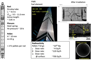
Typically, fuel elements remain in the nuclear power plant (NPP) for 4 cycles (https://www.kkg.ch/upload/cms/user/KKG TB englisch 2016.pdf, June 2017). A NPP generates almost 20 t of spent nuclear fuel (SNF) per year which need to be stored in a water pool for several years. Figure 1 shows the design of a fuel rod, a photo of a PWR fuel element (assembly) and pictures of the UO2 fuel after discharge from the NPP.
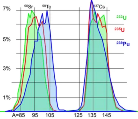
The energy in a NPP is produced by fission of fissile isotopes, such as the natural isotope235U. Only 0.7% of the natural uranium consist of the isotope235U. The effective energy release by fission of235U is about 205.4 MeV per fission. This energy is distributed between 2 fission products, recoil nucleus and 2 to 3 neutrons. The energy of the neutrons is in the range between 0.1 and 10 MeV which is too fast for keeping up a chain reaction. In a LWR, fission is caused by neutrons in the thermal energy range. By interactions with light atoms (hydrogen of the water) the fission neutrons are moderated to thermal energies of 0.025 eV. It needs to be mentioned that fission can be generated also by high-energy neutrons for example in fast reactors. Details of the neutron interactions with matter, the interaction coefficients for scattering, capturing and fission processes as function of the neutron energy are given in the numerous text books on nuclear physics. The mass distribution of the fission products resulting from the fissile isotopes233U, 235U and239Pu are shown in fig. 2. For a burn-up of 50 GWd/t
HM, 5.5% of the initial 235U atoms are affected. The formation of the fission products cause disturbances in
Fig. 1. – Design of a fuel rod (left), photo of a PWR fuel element assembled from fuel rods (middle), fuel after discharge (right).
lattice, oxygen redistribution, reduction of heat conductivity, and changes in specific heat, mechanical properties, formation of fractures and pores. The fission products according fig. 2 are characterized as follows:
– Noble gases (Kr and Xe) and other volatile fission products (FP).
– FPs dissolved as oxides in the UO2 matrix with adequate oxidized valence state.
– FPs forming metallic precipitates.
– FPs forming oxide precipitates
– Actinides dissolved as oxides in the fuel matrix.
If a thermal or epithermal (0.55–10 eV) neutron hits one of the majority uranium atoms 238U, it can be captured forming239U. This isotope is unstable and undergoes beta decay (half-life 23.47 min) forming239Np. Also this isotope undergoes beta decay (t1/2= 2.355 days) forming239Pu. This plutonium isotope has a half-life of 24 114 years and is also fissile. During the 4 years of the fuel in a NPP, 239Pu is formed and partly burned. By neutron capture, also higher actinides are formed.
Fig. 2. – Distribution of the main fission products as a function of the atomic number for 3 fissile isotopes.
From the chemical point of view, the spent nuclear fuel is one of the most complex materials with respect to the elemental composition, the chemical state of the elements and the heterogeneity. Information on the radioactivity of spent nuclear fuel is given in fig. 1.
3. – Reprocessing or direct disposal of spent nuclear fuel
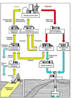
After discharge of the UO2 fuel from a NPP with a burn-up of 50 GWd/tHM, the spent fuel (SNF) contains still 0.8%235U and about 1%239Pu fissile isotopes. Especially in the 1960/1970ies when the total worldwide uranium resources were significantly un-derestimated, many states developed plans to retrieve the fissile materials for further use in NPPs. The objective was a closed fuel cycle with multiple reprocessing and reuse of plutonium (see fig. 3).
The reprocessing processing process is a complicated chemical procedure, dissolving the UO2fuel in hot, highly concentrated nitric acid. Afterwards, the acid solution which contains the fission products, as well as some activation products, the actinides and the complete mass of uranium is treated by the PUREX process. This is a chemical method used to purify fuel for nuclear reactors or nuclear weapons. It is an acronym standing for Plutonium Uranium Redox EXtraction. PUREX is thede factostandard aqueous nuclear reprocessing method for the recovery of uranium and plutonium from used (“spent”, or “depleted”) nuclear fuel. It is based on liquid-liquid extraction ion-exchange.
Fig. 3. – Schematic view of the open and closed fuel cycles. (Picture taken from ENS, Euro-pean Nuclear Society, https://www.euronuclear.org/info/encyclopedia/n/nuclear-fuel-cycle.htm.)
law in Germany, until 1994 reprocessing of used fuel was promoted and direct disposal was forbidden.
During the reprocessing of UO2 fuels different waste streams are generated. These comprise
– Fission gases,
– zircaloy cladding (hulls) of the fuel rods including the foot and end-pieces (solids);
– high-level radioactive waste in HNO3 solution (liquid);
– intermediate-level radioactive wastes mainly in acidic solutions (liquid);
– low-level radioactive wastes, HTO-bearing liquids, decontamination detergents (liquid);
– solid wastes,e.g.filters, etc.
Fig. 4. – International (left) and German classification of radioactive wastes [1].
In the closed fuel cycle, the separated plutonium would be applied to produce mixed uranium plutonium fuels (MOX) to be used in LWRs or in fast reactors.
4. – Classification of wastes
Radioactive wastes do not only originate from reprocessing, but also during the op-eration and decommissioning of NPP, from industrial use (sterilization, radiographic techniques, etc.), from research and from medical applications. The nuclear waste classi-fication applied In Germany is shown in fig. 4, the radioactive wastes are classified with respect to the heat release in a repository. Heat-producing waste comprises the solidified high-level waste from reprocessing, hulls and end-pieces as well as SNF.
All wastes need to be transformed in a solid form before disposing.
4.1.High-level wastes. – For liquid high-level radioactive waste (HLW) from reprocess-ing, the vitrification of the liquid is presently the method of choice. In Europe, vitrified HLW is/was produced by AREVA in La Hague, France, in Sellafield, UK and also at the pilot reprocessing plant WAK in Germany. The molten glass is poured in stainless-steel canisters of 150 l. The outcome of vitrification is a solid waste form with a content of 15–20 wt.% of fission product oxides in a borosilicate matrix. Guarantee values of HLW glass canisters are 3×10¹⁶Bq ofβ/γ activity, 1.4×10¹⁴Bq ofαactivity and a surface dose rate of 1800 Gy/h.
Zircaloy rod cladding (hulls), spacers etc. as well as foot and end-pieces of the fuel elements are compacted and stored in the same type of canisters as the vitrified waste.
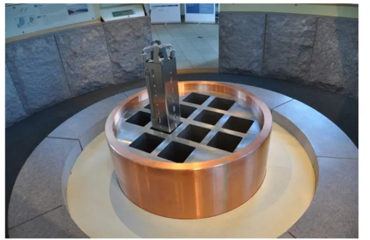
Fig. 5. – Swedish KBS-3 concept: Disposal of a Cu-coated steel canister in a vertical drill hole into the granitic host rock surrounded by clay buffer. (Picture taken from Wikipedia,
https://commons.wikimedia.org/wiki/File:SKB KBS-3.jpg#file.)
Cu layer is considered to be stable under the Scandinavian granitic rock conditions for several 100 000 years (see fig. 5).
4.2. Intermediate- and low-level wastes. – Almost all countries distinguish between long-lived and short-lived Intermediate- (ILW) and low-level waste (LLW). Liquid ILW and LLW from reprocessing are concentrated by evaporation and the concentrates mainly mixed with cement in order to form solid waste forms. Typically these waste forms contain about 10 wt.% of NaNO3salts. In some facilities, the liquid ILW was incorporated in bitumen. At the reprocessing plant in La Hague, France, the bituminization process is replaced by a vitrification process using a “cold crucible” technology [2].
Fig. 6. – Waste types and specific treatment techniques for LWR operational wastes.
4.4. Decommissioning wastes. – Decommissioning wastes represent a huge amount of mass. The total mass of the radiation-controlled area of a large nuclear power plant with a PWR is estimated to 156 500 t. About 143 000 t cover concrete structures. This material can be almost completely conventionally recycled following removal of any sur-face contamination. Only approximately 600 t of the concrete requires final disposal as radioactive waste. The mechanical installations —essentially piping and components— including the entire steel construction (e.g. platforms and mountings) form a mass of around 13 500 t in the radiation-controlled area of a PWR. Among these materials, only around 3 000 t require disposal as radioactive waste and around 500 t as radioactive sec-ondary waste (including from decontamination). The remaining 9800 t can likewise be directly released or recycled after decontamination or melting-down [3]. During the de-commissioning activities each material is analyzed with respect to radiation dose. In the case that the dose is below a certain limit (which is expressed in Bq/g or Bq/cm3) for the different materials and structures such as debris, surfaces, buildings and scrap metal, the materials can be disposed in conventional surface disposal or fed to re-use processes [4]. However, the different European countries follow different disposal concepts. In France, all materials arising from decommissioning of nuclear facilities need to go to specific disposal (very low waste disposal).
5. – Disposal – International disposal projects
Fig. 7. – Comparison of important characteristics of potential host rocks.
site is a challenge. The siting process has to take into account a multitude of differ-ent aspects, scidiffer-entific, social, economic and also ethical aspects. In most countries, the import and export of radioactive wastes are not allowed. For this reason all countries using nuclear power need to take decisions. A summary of the international approaches for deep geological disposal of nuclear waste and the geological challenges in radioac-tive waste isolation was published recently by Lawrence Berkeley and Sandia National Laboratories in the USA (LBNL-1006984, 2016) [5]. It covers the disposal plans of 23 countries worldwide.
Before disposing HLW in a deep underground facility, the heat capacity has to decay below a certain level. This is achieved by interim storage, in many cases for periods of minimum 30 years. Of course, prolonged interim storage might be considered for example in The Netherlands. The Dutch waste management organization COVRA has a license for an interim storage facility for a period of 100 years.
Presently, three host rock types are under consideration for HLW and SNF. These are rock salt which has been investigated in Germany and USA since decades. Crystalline rocks, such as granite are available in Scandinavia and therefore this host rock was selected for Swedish and Finnish disposal concepts. It is also under investigation in Korea and China. In Belgium, an indurated clay rock formation (Boom clay) is under investigation, whereas in Switzerland the Opalinus clay and in France the Callovo argillite is selected. These two clay rocks consist of a mineral assemblage made of illite and calcite as main components. In fig. 7, some important features of the different host rocks are presented.
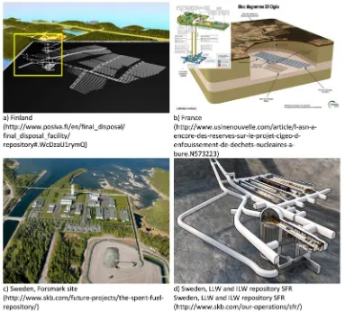
Fig. 8. – European disposal concepts. (Pictures taken from the public web pages of the respective waste management organizations: a) Finland, picture taken from POSIVA OY, Fin-land, http://www.posiva.fi/en/final disposal/final disposal facility/repository#. WcDzaU1rymQ; b) France, picture taken from ANDRA, Agence nationale pour la ges-tion des d´echets radioactifs, France, http://www.usinenouvelle.com/article/l-asn-a- encore-des-reserves-sur-le-projet-cigeo-d-enfouissement-de-dechets-nucleaires-a-bure.N573223; c) Sweden, Forsmark site, picture taken from SKB, Svensk K¨arnbr¨anslehantering AB,http://www.skb.com/future-projects/the-spent-fuel-repository/; d) Sweden, LLW and ILW repository SFR Sweden, picture taken from SKB, Svensk K¨arnbr¨anslehantering AB,
http://www.skb.com/our-operations/sfr/.)
of the repositories have shown that a safe disposal is feasible in all types of host rocks. However, the specific multi-barrier system consisting of technical, geo-engineered and natural barriers as well as the impact of each barrier on the disposal safety is different for the different host rocks.
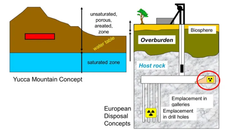
Fig. 9. – Layout and general design of a HLW/SNF repository.
All reasonably discussed disposal concepts for HLW and SNF are based on mines in the host rock. For disposal of heavy disposal casks access tunnels or shafts are foreseen. Some disposal concepts need to demonstrate the possibility of retrieving the wastes for a certain period of time (e.g.France, Germany), whereas other disposal concepts promote disposal “in an irreversible manner” (Finland). It is clear that if the tunnels of a mine have to be accessible over decades, specific layout and constructive measures have to be considered. Figure 8a shows the planned Finnish HLW repository, start of operation is planned for 2025. The yellow square shows the disposal research mine ONKOLO, where site-specific investigations are running. Figure 8b presents the French disposal concept Cig´eo which will be located in the Callovo-Oxfordinan clay formation. The license for construction is expected in 2018, the operation could start after 2025. In the left corner of fig. 8b, the research mine at Bure is shown.
Figure 8c shows a photo of the selected site at Forsmark in Sweden, where the Swedish waste management organization Svensk K¨arnbr¨anslehantering AB (SKB) will construct the HLW repository. It is planned to start operation in 2030. Close to this location, SKB operates the LLW/ILW disposal facility called SFR since 1988. In contrast to the deep disposal concept for HLW, the SFR is situated 50 metres below the bottom of the Baltic and comprises four 160-metre long rock vaults and a chamber in the bedrock with a 50-metre high concrete silo for the most radioactive waste.
Figure 9 shows the design and general layout of repositories. The disposal mine is generally located deep below the groundwater table which guarantees slow groundwater movements and reducing conditions. The only exemption was the US disposal site at Yucca Mountain in Nevada. This site is located in a desert with low precipitation rates which caused problems with corrosion of canister materials.
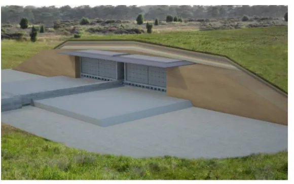
Fig. 10. – Final layout of the Belgian LLW surface disposal at Desel. (Picture taken from ONDRAF·NIRAS, Belgium,https://www.ondraf.be/stockage-en-surface-%C3%A0-dessel.)
Today, deep borehole disposal concepts are under discussion in some countries (5000 m). The concepts are not sufficiently developed and will not be further addressed in this presentation.
For ILW and LLW, disposal in deep geological formations is considered in some coun-tries only (e.g.Germany and Switzerland). Most countries use shallow surface disposals (France, Belgium, Spain, . . . ) for short-lived radioactive wastes. Figure 10 shows the layout of the Belgian LLW disposal at Dessel after final closure of the site. The wastes are stored in drums which are packed in concrete structures. These are placed in build-ings which are finally covered by clay layers. This type of disposal should hold several hundred years until the decay of the most abundant fission products90Sr and137Cs.
As already mentioned, the safety of repositories relay not only on the hostrock, but also on a multi-barrier system. The barriers consist of constructions and materials with the following properties:
– waste packages, cansisters, etc.;
– barrieres against penetration of groundwater;
– barriers against migration of radionuclides (sorption properties);
– chemical “buffering” (pH, redox, composition of solutions . . . );
– mechanical stability;
– heat conductivity (for HLW/SNF);
– decoupling of canister and hostrock (in the case of crystalline hostrocks).
The barrier materials need to be designed according to the hostrock, groundwater composition and the expected long-term evolution of the system.
6. – Safety analysis, data and models
Operating of an underground disposal requires a series of measures to guarantee the orperational safety. One important aspect accounts for non-reactive waste forms (WIPP accident 2014 [6,7]). The disposal of radioactive wastes in deep underground repositories aims at a multitude long-term safety relevant features. These comprise:
– concentration of radiotoxic materials,
– isolation from biosphere,
– protection of environment and population,
– protection against intended and unintended access,
– safeguards (nonproliferation of fissile materials).
Additionally, ethical and societal features are of high importance:
– passive safety,
– unattended (maintenance free),
– no burdens for future generations.
Due to the long half-lives of the actinides and some fission products (135Cs, 99Tc, 129I), these features have to be maintained over long periods of time. In Germany, safety
for 1 million years is claimed by law.
In the underground, below the groundwater table, water is omnipresent and contact of water with the waste forms cannot be excluded completely. It is clear, that the different host rocks provide different probabilities of water penetration to the wastes. From a thermodynamic viewpoint, the components disposed of are not inert in contact with water, but tend to react over long periods of time. The reactions include interactions with backfill/buffer materials, corrosion of canister materials, and leaching and corrosion of the waste itself. Safety assessment is based on models which simulate the whole suite of possible processes in a disposal including corrosion, waste form behavior, radionuclide mobilization and retention. The reactions and reaction rates depend on the availability of the relevant reactants, inter alia of water and groundwater constituents. Both, the transport of water and of radionuclides is affected by reactions causing alterations of the mineralogy and consequently of the porosity and permeability of near-field barriers. It is clear that the models require reasonable understanding and databases.
Fig. 11. – Experiments with SNF in the shielded boxes at KIT-INE.
6.1.Alteration/Corrosion of waste forms.
HLW glass
The mechanism of glass dissolution is primarily driven by two main reactions that are opposed to one another: These are the parallel reactions of “matrix dissolution” of the glass and “water diffusion/hydration of the glass matrix/ion exchange reactions” [8]. The fastest process is the rate-dominating process in parallel reactions, whereas in sequential reactions, the slowest reaction governs the rate. The combination of the processes lead to consecutive regimes of glass alteration having different reaction rates. First, the for-mation of the gel layers and/or the accumulation of glass constituents in solution, later the formation of secondary phases take place and the glass corrosion rate decreases. with time. Radionuclides distributed homogeneously in the glass matrix are released. Soluble elements remain dissolved in the attacking water, less soluble elements react according to their thermodynamic potentials forming solids or being sorbed onto solid phases.
SNF
Fig. 12. – Oxidation states and electron configuration of the disposal relevant actinide elements.
with radiolytical compounds (Cl−, Br−). The α-radiolytical processes depend on the specificα-activity of the SNF which decays with time [15].
Cemented waste forms
Cemented waste forms are produced using relatively high water to cement ratios which are representative for the pore system of the cement matrix. Groundwater penetrates into the pore system and starts leaching of soluble components such as the portlandite (Ca(OH)2). Depending on flow-through processes, the whole portlandite might be dis-solved causing a decrease of the pH in the cement pores. As a consequence, the main constituents of the hardened cement the calcium-silicate phases are no longer stable and decompose [16]. In the case of contact of cement products with magnesium chloride brines, the decomposition rate is no longer controlled by diffusion but by Ca-Mg ex-change reactions. This reaction shows a much faster degradation of cemented waste forms [17]. Soluble elements (Cs) are released quickly, in cement incorporated actinides are dissolved according their thermodynamic properties [18].
Fig. 13. – Laser spectroscopic characterization of dissolved and sorbed species at KIT-INE.
be different methods such as X-ray diffractometry or extended X-ray absorption fine structure measurements (EXAFS) and related methods.
Due to the strong sorption capacity of the actinides, the elements might sorb onto groundwater colloids or form eigen-colloids. Specific techniques have been developed for detection and quantification of the colloids (e.g.Laser-induced breakdown detection LIBD).
6.3. Sorption onto artificial and natural barrier materials. – Radionuclides can be sorbed onto the different solid materials of the barriers. The sorption processes comprise
– ion-exchange reactions,
– surface complexation reactions (outer and inner surface complexes),
– surface precipitation by co-precipitation and by redox controlled processes.
The sorption coefficients are strongly influenced by the pH of the groundwater and the dissolved ligands such as carbonate. It is also clear that sorption takes place onto the surfaces of the solids. The sizes and properties of the surfaces play an important role. For this reason, the sorption data bases (e.g.Vandergraaf [19]) can hardly be transferred to different systems. Sorption data need to be determined site specifically.
For quantification of the sorption processes and characterization of the relevant surface complexes highly sophisticated methods are required. These techniques include X-ray photoelectron spectroscopy, XPS, TRLFS and EXAFS/XANES.
certainly the slowest process. Advectively driven processes are significantly faster. The following mechanism might trigger the water/radionuclide transport:
– thermal convection,
– density driven convective flow,
– forced flow as consequence of gas formation, – forced flow as consequence of volume changes.
One can expect that the design and the barrier system of a HLW repository would prevent thermal and density driven flow processes, also the changes of open volumes by swelling (clay) or convergence (rock salt) are relatively slow processes and can be evaluated reasonably.
As the repository system evolves, gases may be produced, such as hydrogen from the corrosion of metals and from the radiolysis of water, and radon from the radioactive decay of some of the waste. If present, biodegradable wastes can also produce carbon dioxide and methane. Understanding how these gases move in a repository setting was a topic of the Euratom FORGE project, which studied key gas migration issues in repository performance assessment (https://www.bgs.ac.uk/forge/).
6.5. Models and safety analysis. – Demonstration of the safety of a nuclear waste disposal requires numerical model calculations. However, in this context models results are representative only for the aspect for which the model has been developed. Extrap-olations beyond the parameter range on which the model is based are not possible. This is also true for the parameter used in the calculations. Besides reasonable models one has also to deal with natural processes and unpredictive human activities. Further the models as well as the data have uncertainties which need to be addressed.
Deterministic safety analysis
For safety analysis specific tools are used. As the future is unknown, safety analyses are build-up on the concept of scenarios. This concept representing the deterministic safety analysis is demonstrated in fig. 14. In a first step, a selection of the features, events, and processes (FEP) is required. The FEP should cover all conceivable facts and figures of the disposal system including wastes, barriers and hostrock. Relevant FEP can be selected from FEP databases or from site specific information. A scenario is constructed by combination of the selected FEPs. A common definition is as follows: “A scenario is specified by a combination of some FEPs which characterize one potential evolution of the disposal system”. Especially in the case of an incidence scenario, the initiating FEP is of high importance.
After the combination of the FEPs to form a scenario, a model is developed, mainly as a numerical code. Initial and boundary conditions as well as model parameters are derived from site-investigation or from experimental data with wastes, barriers, etc. This process delivers results for a multitude of scenarios and realizations with different sets of parameters. Figure 14 shows the different steps which are required for deducing the long-term performance and the resulting dose rates from FEPs and scenarios.
Fig. 14. – Scenario: From FEP to performance assessment and safety analysis.
One important question is concerned with the weighting of the results to be used for safety analysis. This can be done by probabilistic tools.
Probabilistic Safety Analysis
Probabilistic safety assessment (PSA) is an established technique to numerically quan-tify risk measures in nuclear power plants. It is also applied for disposal safety analysis. PSA comprises a model of the disposal, in which all safety relevant systems are modelled and logically linked together to determine the overall likelihood of radionuclide release and the dose to man(1). System failures are identified and quantified by models like Fault Trees (FT) which deduce logical combinations of the FEPs. At the lowest level, the FEPs of the fault trees are assigned probability distributions. These probability dis-tributions are propagated up through the tree logic to reach a probability distribution of the top event. The PSA methodology is a logical, deductive technique which specifies an undesired top event and uses fault trees and event trees to model the various parallel and sequential combinations of processes that might lead to an undesired event such as radionuclide release. The number of combinations that might lead to this incident increases exponentially with the number of modelled components. Consequently, effec-tive computer codes and quantification techniques are necessary to solve any large scale problem. The PSA models are traditionally built from logical Boolean expressions. In PSA such logical expressions are typically based on coupled event tree models. Event trees (ET) depict the potential event sequences from the initiating event to the
associ-(1) The detriment adjusted nominal risk coefficient for cancer and hereditary effects by radiation
is 0.057 per Sv [20].
Fig. 15. – TSPA Model Architecture. (Picture taken from C. W. Hansen et al., San-dia National Laboratories, USA,http://energy.sandia.gov/wp-content//gallery/uploads/ SAND2010-3754C.pdf.)
ated consequences. The ET begins with the initiating event. An initiating event (IE) could be failure of a barrier. For the Total System Performance Assessment (TSPA) of the Yucca Mountain, four questions were underlying the probabilistic safety analysis:
1. What events and processes can take place at the facility?
2. How likely are these events or processes?
3. What are the consequences of these events or processes?
4. How certain are the answers to the first 3 questions?
The complexity of the TSPA model architecture is shown in fig. 15. (GoldSim is a dynamic, probabilistic simulation software developed by GoldSim Technology Group.)
7. – Conclusions
exist to dispose of these wastes in deep underground facilities. Due to the different geologic settings of the countries, different host rocks can be selected. In few countries, such as in Germany, several suited host rock formations are available.
Development and demonstration of safe disposal of radioactive wastes is a multi-disciplinary task requiring experiences from nuclear physicists, chemists, geologists, min-ing engineers and many more scientific disciplines. However, even if a disposal concept sounds scientifically and technically reasonable and safe, it must be accepted by the society and by the population living close to the site.
The safe isolation of the wastes from the environment over the long periods of time can be demonstrated by model calculations and safety analyses. Deterministic and prob-abilistic procedures for safety analyses are described. Scientists may accept the method-ologies, can review the models and databases as well as evaluate the conclusions drawn from the experimental findings on which the data were determined. Of course, different opinions of scientists exist. These different opinions can be disputed on a scientific level. However, it is necessary to communicate the concepts, analyses and results to the society including politicians, the population at the site and action groups. The communication of scientific facts and data is extremely complicated: Breaking facts and figures down to easily understandable statements for the public could be misinterpreted by the scientific community. In the context of safe disposal of nuclear wastes the communication to the public is indispensable and procedures resolving this deficit need to be developed.
REFERENCES
[1] Nickel H., “The spent fuel and waste management concept of German nuclear power
plants”Atomwirtsch.-Atomtech.,37(1992) 368.
[2] Boen R., “L’elaboration de verres nucleaires en creuset froid”Clefs CEA,59(2010) 17.
[3] Working Panel Waste management of VGB PowerTech e.V., “Waste disposal for nuclear power plants”, VGB PowerTech e.V., Essen, 2012.
[4] StrlSchV, “Verordnung ¨uber den Schutz vor Sch¨aden durch ionisierende Strahlen”BGBl I 2001, 1714, (2002, 1459) vom 20. Juli 2001. Ge¨andert durch Art. 2 V v. 18. 6.2002 I 1869, 2001.
[5] Faybishenko B., Birkholzer J., Sassani D. andSwift P.,International Approaches
for Deep Geological Disposal of Nuclear Waste: Geological Challenges in Radioactive Waste Isolation, Fifth Worldwide Review(Lawrence Berkeley National Laboratory, Sandia National Laboratories) LBNL-1006984, 2016.
[6] DOE U. S., Accident Investigation Report: Underground Salt Haul Truck Fire at the
Waste Isolation Pilot Plant February 5, 2014 (U.S. Department of Energy, Office of Environmental Management) 2014.
[7] DOE U. S., Accident Investigation Report: Phase 1 Radiological Release Event at the
Waste Isolation Pilot Plant on February 14, 2014 (U.S. Department of Energy, Office of Environmental Management) 2014.
[8] Grambow B., “Coupled modelling of the source-term for radionuclide release from nuclear
waste forms in the near-field”Geochimica Et Cosmochimica Acta,69(2005) A408. [9] Kienzler B., Duro L., Lemmens K., Metz V., Pablo J. d., Valls A., Wegen D. H.,
Johnson L. and Spahiu K., “Summary of the Euratom Collaborative Project
FIRST-Nuclides and Conclusions for the Safety Case”Nucl. Technol.,198(2017) 260.
[10] Johnson L. H., Garisto N. and Stroes-Gascoyne S., “Used-fuel dissolution sudies
in Canada” inWaste Management 1985 Tucson, Arizona, March 24-28, 1985 (Arizona Board of Regents, Tucson, AZ) 1985, pp. 479–482.
[11] Ferry C., Lovera P., Poinssont C.andJohnson L., “Quantitative assessment of the
instant release fraction (IRF) for fission gases and volatile elements as a function of burnup and time under geological disposal conditions”, in Scientific Basis for Nuclear Waste Management XXVII, Kalmar, Sweden, 2003 (Materials Research Society, Warrendale, PA, USA) 2003, pp. 35–40.
[12] Johnson L., G¨unther-Leopold I., Kobler Waldis J., Linder H. P., Low J., Cui D., Ekeroth E., Spahiu K.andEvins L. Z., “Rapid aqueous release of fission products from
high burn-up LWR fuel: Experimental results and correlations with fission gas release”J. Nucl. Mater.,420(2012) 54.
[13] Gonz´alez-Robles Corrales E., “Study of radionuclide release in commercial UO2Spent
Nuclear Fuel - Effect of burn-up and high burn-up structure”, PhD, Universitat Polit`ecnica de Catalunya, Barcelona, 2011.
[14] Metz V., Geckeis H., Gonz´alez-Robles E., Loida A., Bube C.and Kienzler B.,
“Radionuclide behaviour in the near-field of a geological repository for spent nuclear fuel” Radiochim. Acta,100(2012) 699.
[15] Spahiu K., Devoy J., Cui D. Q.andLundstrom M., “The reduction of U(VI) by near
field hydrogen in the presence of UO2(S)”Radiochim. Acta,92(2004) 597.
[16] Berner U. R., “Evolution of Pore Water Chemistry during Degradation of Cement in a
Radioactive Waste Repository Environment”Waste Management,12(1992) 201. [17] Kienzler B., Borkel C., Metz V.andSchlieker M.,Long-Term Interactions of
Full-Scale Cemented Waste Simulates with Salt Brines(Karlsruhe Institute of Technology) KIT SR 7721, 2016.
[18] Kienzler B., Metz V., Brendebach B., Finck N., Plaschke M., Rabung T., Rothe J. and Schild D., “Chemical status of U(VI) in cemented waste forms under saline
conditions”Radiochim. Acta,98(2010) 675.
[19] Vandergraaf T. T., Ticknor K. V.andMelnyk T. W., “The selection of a Sorption
Data Base for the Geosphere Model in the Canadian Nuclear Fuel Waste Management Program”J. Contaminant Hydrol.,13(1993) 327.
[20] International Commission on Radiological Protection (ICRP), Biological and Epidemi-ological Information on Health Risks Attributable to Ionising Radiation: A Summary of Judgements for the Purposes of Radiological Protection of Humans, Committee 1 Task Group Report: C1 Foundation Document (Annex A of Main Recommendations)Vol. 12/ 180/06, 2006.
![Fig. 4. – International (left) and German classification of radioactive wastes [1].](https://thumb-us.123doks.com/thumbv2/123dok_us/8033605.1337013/6.482.110.373.64.246/fig-international-left-german-classication-radioactive-wastes.webp)