University of Windsor University of Windsor
Scholarship at UWindsor
Scholarship at UWindsor
Electronic Theses and Dissertations Theses, Dissertations, and Major Papers
10-19-2015
Efficient Architecture and Implementation for NTRU Based
Efficient Architecture and Implementation for NTRU Based
Systems
Systems
Bingxin Liu
University of Windsor
Follow this and additional works at: https://scholar.uwindsor.ca/etd
Recommended Citation Recommended Citation
Liu, Bingxin, "Efficient Architecture and Implementation for NTRU Based Systems" (2015). Electronic Theses and Dissertations. 5438.
https://scholar.uwindsor.ca/etd/5438
Efficient Architecture and Implementation for NTRU Based
Systems
by
Bingxin Liu
A Thesis
Submitted to the Faculty of Graduate Studies
through Electrical and Computer Engineering
in Partial Fulfilment of the Requirements for
the Degree of Master of Applied Science at the
University of Windsor
Windsor, Ontario, Canada
2015
c
Efficient Architecture and Implementation for NTRU Based Systems
by
Bingxin Liu
APPROVED BY:
Dr. Henry. Hu
Department of Mechanical, Automotive, & Materials Engineering
Dr. H. K. Kwan
Department of Electrical and Computer Engineering
Dr. H. Wu, Supervisor
Department of Electrical and Computer Engineering
DECLARATION OF
CO-AUTHORSHIP/PREVIOUS PUBLICATION
I DECLARATION OF CO-AUTHORSHIP
I hereby declare that this thesis presents the research outcome under the supervision
of professor, Dr. Huapeng Wu. In all cases, the key ideas, primary contributions,
experimental designs, data analysis and interpretation, were performed by the author,
with the review and revision being provided by Prof. Wu. This joint research was
submitted to the International Midwest Symposium on Circuits and Systems 2015,
as specified in the declaration below.
I am aware of the University of Windsor Senate Policy on Authorship and I certify
that I have properly acknowledged the contribution of other researchers to my thesis,
and have obtained written permission from each of the co-author(s) to include the
above material(s) in my thesis.
I certify that, with the above qualification, this thesis, and the research to which
it refers, is the product of my own work.
II DECLARATION OF PREVIOUS PUBLICATION
This thesis includes 1 original paper that has been previously submitted for
publica-tion in a peer reviewed conference, as follows:
Thesis
Chapter/Section Publication title/full citation Publication status
Chapter 4
Efficient Architecture and Implementation for NTRUEncrypt System, IEEE 58th International Midwest Symposium on Circuits and Systems (MWSCAS 2015), Aug 2-5, Fort Collins, Colorado, USA
I certify that I have obtained a written permission from the copyright owner to
include the above published material in my thesis. I certify that the above material
describes work completed during my registration as graduate student at the University
of Windsor.
I declare that, to the best of my knowledge, my thesis does not infringe upon
anyones copyright nor violate any proprietary rights and that any ideas, techniques,
quotations, or any other material from the work of other people included in my
thesis, published or otherwise, are fully acknowledged in accordance with the standard
referencing practices. Furthermore, to the extent that I have included copyrighted
material that surpasses the bounds of fair dealing within the meaning of the Canada
Copyright Act, I certify that I have obtained a written permission from the copyright
owner(s) to include such material(s) in my thesis. I declare that this is a true copy
of my thesis, including any final revisions, as approved by my thesis committee and
the Graduate Studies office, and that this thesis has not been submitted for a higher
ABSTRACT
NTRU (Nth degree Truncated polynomial Ring Units) is probably the only post
quantum public key cryptosystem suitable for practical implementation. Recently,
several NTRU based systems have also been shown having property of homomorphic
encryption with important application in cloud computing security.
In this thesis, several efficient algorithms and architectures for NTRUEcrypt
sys-tem and for NTRU based homomorphic encryption syssys-tem are proposed. For
NTRU-Encrypt system, a new LFSR (linear feedback shift register) based architecture is
firstly presented. A novel design of the modular arithmetic unit is proposed to
re-duce the critical path delay. The FPGA implementation results have shown that the
proposed design outperforms all the existing works in terms of area-delay product.
Secondly, a new architecture using extended LFSR is proposed for NTRUEncrypt
system. It takes advantage of small polynomials with many zero coefficients, and
thus significantly reduces the latency of the computation with modest increase of
the complexity. Thirdly, a systolic array architecture is proposed for NTRUEncrypt.
There is only one type of PE (process element) in the array and the PE was designed
with optimized arithmetic. The systolic array yields all the output in N clock cycles.
Two new architectures are proposed for computation of NTRU based fully
ho-momorphic encryption system. One architecture uses LFSR with a novel design of
the modular multiplication unit, and the other proposed architecture is systolic array
DEDICATION
To my loving parents:
Father: Bocai Liu
ACKNOWLEDGEMENTS
I would like to express my sincere gratitude and appreciation to everyone who
helped make this thesis possible. I am deeply indebted to my supervisor Prof.
Huapeng Wu, Professor of Electrical and Computer Engineering at University of
Windsor, for guiding me throughout the writing of this thesis. As one of best
teach-ers I have ever had, Professor Wu impressed upon me that a good teacher instructs
students in matters far beyond those in textbooks. His broad knowledge and logical
way of thinking have been of great value; without his detailed and constructive
com-ments on my research, none of this thesis would be possible. I would also grateful to
my colleagues and friends, Yiruo He, Zheng Gong and Wu Zheng and for their time
and support. Finally, I with to extend my gratitude to everyone at UWindsors Faculty
of ECE for their efforts during my study in the M.A.Sc. Program. I also gratefully
acknowledge the financial support form University of Windsor and Professor Huapeng
Wu.
TABLE OF CONTENTS
DECLARATION OF CO-AUTHORSHIP/
PREVIOUS PUBLICATION iii
ABSTRACT v
DEDICATION vi
ACKNOWLEDGEMENTS vii
LIST OF TABLES xii
LIST OF FIGURES xiii
LIST OF ALGORITHM xiv
LIST OF ACRONYMS xv
1 INTRODUCTION 1
1.1 Motivation . . . 1
1.2 Our Contribution . . . 4
1.3 Dissertation Organization . . . 4
2 MATHEMATICAL PRIMITIVES 6 2.1 Lattices . . . 6
2.1.1 Definitions . . . 6
2.1.2 Ideal Lattice . . . 7
2.3 NTRUEncrypt Public Key Cryptosystem . . . 9
2.3.1 Parameter Selection . . . 9
2.3.2 Key Generation . . . 11
2.3.3 Encryption . . . 12
2.3.4 Decryption . . . 12
2.3.5 Why the Decryption of NTRUEncrypt Works . . . 12
2.3.6 Discussions on NTRUEncrypt Optimization . . . 12
2.4 Revised NTRUEncrypt Public Key Cryptosystem . . . 13
2.4.1 Parameter Selection . . . 13
2.4.2 Key Generation . . . 14
2.4.3 Encryption . . . 14
2.4.4 Decryption . . . 15
3 A REVIEW OF EXISTING WORK 16 4 PROPOSED LFSR ARCHITECTURE TO IMPLEMENT NTRU-ENCRYPT 18 4.1 Linear Feedback Shift Register . . . 18
4.2 Proposed Truncated Polynomial Ring Multiplier . . . 19
4.3 Proposed Encryption Architecture . . . 20
4.3.1 Proposed Modular Arithmetic Unit . . . 20
4.3.2 Proposed Encryption Architecture . . . 22
4.4 Proposed Decryption Architecture . . . 25
4.4.1 Proposed Modular Unit . . . 25
4.4.2 Proposed Decryption Architecture . . . 28
4.5 Implementation of Proposed Encryption Architecture . . . 28
4.5.1 Implementation Result . . . 29
5 PROPOSED EXTENDED LFSR ARCHITECTURE TO
IMPLE-MENT NTRUENCRYPT 31
5.1 General Ideal . . . 31
5.2 Extended Linear Feedback Shift Register . . . 33
5.3 Proposed Extended Modular Arithmetic Unit . . . 33
5.4 Proposed NTRUEncrypt Architecture with Extended LFSR . . . 36
5.5 Implementation of Proposed Encryption Architecture . . . 39
5.5.1 Implementation Results . . . 39
5.5.2 Comparison . . . 40
5.6 Discussion on Parameter Selection in Hardware Implementation . . . 40
6 PROPOSED SYSTOLIC ARRAY ARCHITECTURE TO IMPLE-MENT NTRUENCRYPT 42 6.1 Systolic Array . . . 42
6.2 Algorithm . . . 43
6.3 Proposed NTRUEncrypt Architecture with Systolic Array . . . 44
7 NTRU APPLICATION IN CLOUD SECURITY 48 7.1 Homomorphic Encryption . . . 48
7.2 NTRU based Fully Homomorphic Encryption System . . . 48
7.2.1 Key Generation . . . 49
7.2.2 Encryption . . . 50
7.2.3 Decryption . . . 50
7.2.4 Evaluation . . . 50
7.3 Proposed Architectures for NTRU based FHE Systems . . . 50
7.3.1 LFSR based Architecture . . . 51
REFERENCES 58
LIST OF TABLES
2.1 Recommended Parameters for NTRUEncrypt [1] . . . 11
2.2 Parameters for Revised NTRUEncrypt [2] . . . 14
4.1 Operations Supported with the Modular Arithmetic Unit . . . 21
4.2 Register Contents for LFSR Based NTRUEncrypt (Encryption) . . . 24
4.3 Look Up Table for Modular Unit . . . 26
4.4 Simulation Result for LFSR Based NTRUEncrypt (Encryption) . . . 29
4.5 Simulation Result with Different Parameter Sets . . . 29
4.6 Comparison of Proposed LFSR Architecture with Other Exist Works 30
5.1 Number of “0, 0” Pair in Different Parameter Set . . . 32
5.2 Operations Supported with the Extended Modular Arithmetic Unit . 34
5.3 Average Clock Cycle for Different Parameter Sets . . . 37
5.4 Register Contents for Extended LFSR Based NTRUEncrypt . . . 38
5.5 Simulation Result with different Parameter Set (Extended LFSR) . . 39
LIST OF FIGURES
2.1 A Two-dimensional Lattice . . . 7
4.1 Linear Feedback Shift Register . . . 19
4.2 Proposed Truncated Polynomial Ring Multiplier . . . 20
4.3 Modular Arithmetic Unit . . . 21
4.4 Proposed Modular Arithmetic Unit . . . 22
4.5 LFSR Based NTRUEncrypt (Encryption) . . . 23
4.6 Proposed Modular Unit . . . 27
4.7 LFSR Based NTRUEncrypt (Decryption) . . . 28
5.1 Extended Linear Feedback Shift Register . . . 33
5.2 Extended Modular Arithmetic Unit . . . 34
5.3 Proposed Extended Modular Arithmetic Unit . . . 35
5.4 Extended LFSR Based NTRUEncrypt . . . 37
6.1 Encryption Operation in Vertical Form . . . 44
6.2 Modified Encryption Operation in Vertical Form . . . 45
6.3 Processing Element . . . 45
6.4 Systolic Array Based NTRUEncrypt . . . 46
7.1 LFSR based Truncated Polynomial Ring Multiplier for NTRU based FHE . . . 52
7.2 Modified Truncated Polynomial Ring Multiplication for NTRU based FHE in Vertical Form . . . 53
7.3 PE for Positive Elements . . . 53
7.4 PE for Negative Elements . . . 54
LIST OF ALGORITHMS
2.1 Parameter Generation Function for NTRUEncrypt [3] . . . 10
4.1 Multiplication in Truncated Polynomial Ring . . . 19
4.2 Proposed Modular Arithmetic Unit . . . 21
4.3 LFSR Based NTRUEncrypt (Encryption) . . . 23
4.4 Shift Coefficient Operation . . . 25
4.5 Modulo 3 Operation . . . 26
5.1 Proposed Extended Modular Arithmetic Unit . . . 35
5.2 Extended Encryption in NTRUEncrypt . . . 36
LIST OF ACRONYMS
ECC Elliptic Curve Cryptosystem
EMAU Extended Modular Arithmetic Unit
FHE Fully Homomorphic Encryption
HE Homomorphic Encryption
LFSR Linear Feedback Shift Register
MAU Modular Arithmetic Unit
MAU Modular Unit
1
INTRODUCTION
1.1
Motivation
The rapid development of internet and technology have provided vast areas of new
opportunities and potential sources of efficiency for individuals and organizations
of all sizes. Cybersecurity, which refers to the technologies and processes designed
to protect computers, networks and data from unauthorized access, vulnerabilities
and attacks, becomes a critical issue for people. Cryptography provides the core
technology for cybersecurity. There are two types of cryptographic systems available,
symmetrical key system and asymmetrical key system.
Asymmetrical key system (also called public key system) is a class of cryptographic
algorithms which requires two separate keys: a public key to encrypt messages and
a private key to decrypt messages. Asymmetrical key systems, unlike symmetric key
systems, do not require a secure communication channel for the initial exchange of one
(or more) secret keys between the parties and thus they can provide very important
and unique security services such as key distribution and digital signature.
RSA and elliptic curve cryptosystem (ECC) are two currently popular public
key systems in modern cryptography. All these asymmetrical key systems are based
on some hard mathematical problems. In another word, breaking an asymmetrical
system is mathematically equivalent to solving a certain hard problem. For instance,
integer factorization and elliptic curve discrete logarithm are the underlying hard
problems for RSA and elliptic curve cryptosystems, respectively. These cryptography
systems are considered to be secure today since no efficient algorithm exists to solve
their underlying hard problems.
However, this situation will change with emerging of quantum computing
efficient in solving many hard mathematical problems. For example, Shor [4] find
efficient quantum algorithm for solving integer factorization and discrete logarithm,
which indicates that both RSA and elliptic curve cryptosystems will not be secure
anymore with availability of quantum computers. Therefore there is a need for
cryp-tographic technologies that are still secure in the age of quantum computers. Studies
of these cryptographic technologies are referred as post-quantum cryptography [5].
The current research in the area of post-quantum cryptography is mainly focused
on four approaches. These approaches and some typical cryptography systems are
listed as follows:
• Code-based cryptography
– McEliece encryption [6] and Niederreiter signature [7]
• Hash-based cryptography
– Lamport signature [8] and Merkle signature [9]
• Multivariate cryptography
– Rainbow signature scheme [10]
• Lattice-based cryptography
– Learning with Errors [11] and NTRU [12]
Among the four post-quantum cryptography sub-areas, lattice based cryptography
relies on the worst-case hardness of lattice problems, it can provide strong security
guarantees, efficient implementations and great simplicity. One well known example
of lattice based systems is NTRU, which is probably the most practical system among
all the existing post-quantum cryptosystems.
NTRU was firstly developed by Hoffstein, Pipher and Silverman from Brown
encryption and NTRUSign is used for digital signature. NTRU has been adopted by
IEEE P1363.1 standards under the specifications for lattice-based public-key
cryp-tography since 2009 [1]. In 2009, D. Stehl´e,et al. introduced a revised NTRUEncrypt
scheme [13] which is a provably secure variant NTRUEncrypt. The revised scheme is
likely to be less efficient than NTRUEncrypt, but it can provide higher security since
it is established under lattice problem in its worst case.
Recently, with the development of cloud computing, there is a requirement on
security that allows computations to be carried out on encryption data, while
pre-serving the privacy of the message. This encryption scheme is called homomorphic
encryption(HE). Homomorphic encryption can be divided into two types, partially
homomorphic encryption which allows only addition or multiplication operation and
fully homomorphic encryption(FHE) which supports arbitrary computation on
ci-phertexts. The first FHE is proposed by Craig Gentry [14] [15] [16]. It is based on
the worst-case problems over ideal lattices. Several optimizations and
implementa-tion were proposed in [17] [18] [19] [20] and [21]. But the large size of ciphertext and
the efficiency bottleneck limit the develop of FHE. More efficient new schemes were
developed. See for example [22] [23] [24] and [25]. Most of these schemes are based
on the hardness of the learning with errors (LWE) problem [11] which is as hard to
solve as several worst-case lattice problems. However, in 2012, L´opez-Alt et al. [26]
found some fully homomorphic properties in the revised NTRUEncrypt scheme and
proposed a fully homomorphic scheme based on NTRU system. The scheme is
ap-pears to be efficient. More recently, a modify scheme is proposed to make the security
of this NTRU based FHE depends only on standard lattice assumptions [27].
Sev-eral implementations on these NTRU based FHE were proposed in [28] [29] and [30].
Because of these new found properties, NTRU system attract the public attention
1.2
Our Contribution
In this thesis, we propose some efficient hardware architectures for both original
NTRUEncrypt system and revised NTRUEncrypt system which can be extended to
FHE. More specifically we
• proposed an linear feedback shift register (LFSR) architecture to implement
both encryption and decryption of NTRUEncrypt system.
• proposed an extended LFSR architecture which take advantage of large number
of zero coefficients of the input. A parameter selection optimization for hardware
is also introduced.
• presented a systolic array architecture for efficient implementation of
NTRU-Encrypt.
• propose two new architectures with one LFSR based and the other systolic
array based for implementation of NTRU based fully homomorphic encryption
system.
1.3
Dissertation Organization
An organization of the rest of this thesis is as follows. Chapter 2 presents some
mathematical background and gives a brief introduction of NTRUEncrypt algorithm
and revised NTRUEncrypt algorithm. A brief overview of previous works is shown
in Chapter 3. Chapter 4 presents a new hardware architecture based on LFSR for
NTRUEncrypt with FPGA implementation result. Comparison between our work
and previous works is also given. Chapter 5 describes an extend LFSR structure
improve to efficient of our design. An FPGA implementation result will be also
presented. Chapter 6 proposed a new hardware architecture based on systolic array.
and presents two architectures to implement the polynomial multiplication for FHE
with NTRU based systems. Finally, the last chapter concludes the paper and discusses
2
MATHEMATICAL PRIMITIVES
This chapter introduces relevant mathematical background related to the NTRU and
NTRU based systems that include definition of lattices as well as the hard problems
in lattice that has a significant place in cryptography, and the definition of truncated
polynomial ring and its operations. The encryption and decryption algorithms of
NTRU system and revised NTRU system will also be covered in this chapter.
2.1
Lattices
Lattices have been extensively studied recently by cryptographers for quite some time,
in both the field of cryptanalysis and a source of hard problems to build encryption
schemes. We begin with some definitions and brief discussion of lattices.
2.1.1 Definitions
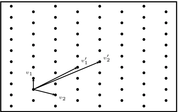
Let the real vector space be denoted by Rn. A lattice L is a discrete subset of Rn. Every lattice in Rn can be generated from a basis for the vector space by forming all linear combinations with integer coefficients.
Letv1, v2, . . . , vnbe linearly independent vectors inRn. Then the vectorsv1, v2, . . . , vn
can be viewed as basis of latticeL. The set of latticeLcan be expressed as an integer
linear combination of basis vectors as follows:
b b b b b b b b b b b b b b b b b b b b b b b b b b b b b b b b b b b b b b b b b b b b b b b b b b b b b b b b b b b b b b b b b b b b b b b b
b b b b
v1
v2
v′1 v′2
Fig. 2.1: A Two-dimensional Lattice
A lattice has many bases. Two possible bases, {v1, v2} and {v10, v02}, for a two
dimensional lattice are shown in Fig.2.1. A lattice is integral if it is contained in
n-dimensional integer vector spaceZnand it is called rational if it is contained in Qn, where Q denote the set of rational numbers [1]. Zn is a simple example of a lattice inRn.
2.1.2 Ideal Lattice
Ideal lattice has important applications place in cryptography. It is a new class of
lattice that includes cyclic lattices as a special case. In general terms, ideal lattices
are lattices corresponding to ideals in rings of the form Z[x]/hfi for some irreducible
polynomial f(x) of degree n [31]. Cyclic lattices are a special case of ideal lattices
2.1.3 Hard Problem in Lattices
Shortest vector problem(SVP) and closest vector problem (CVP) are two fundamental
hard problems in lattices. The general CVP is known to be NP-hard1 and the SVP
is NP-hard under a randomized reduction hypothesis.
The CVP is to find a lattice point closest to the given target point with respect to a
lattice basis. It is the underlying hard problem for NTRUEncrypt system. Encryption
is a matter of selecting a target point. Decryption is a matter of mapping the target
point back to the closest lattice point.
2.2
Truncated Polynomial Ring with Modular Arithmetic
Ntru system is based on the hardness of problems for lattices that can be represented
as ideals in the ringR =Z[x]/(xn−1). That means the basic NTRU operations take
place in the ring of convolution polynomials R = Z[x]/(xn−1), where n is prime.
That is why it is called NTRU, short for Nth Degree Truncated Polynomial Ring Unit.
The set of degree n−1 truncated polynomial can be denoted by R=Z[x]/(xn−1),
whereZ[x] is the set of polynomials with integer coefficients and taken modulo xn−1.
A polynomial a(x) ∈ R can be expressed as
a(x) =an−1xn−1 +....+a0 ={an−1, an−2, ...., a0} (1)
Let b(x) = bn−1xn−1 +....+b0 be another truncated polynomial in R.
Addi-tion operaAddi-tion a(x) + b(x) can be performed by simply adding their corresponding
coefficients.
a(x) +b(x) = (an−1+bn−1)xn−1+ (an−2+bn−2)xn−2....+ (a0+b0) (2)
Multiplication is a little complex. The product of two polynomials is given by
a(x)×b(x) =cn−1xn−1+....+c1x+c0 (3)
where
ck =
X
i,j=0,1,...,n−1
i+j=k modn
aibj, k= 0,1, ..., n−1 (4)
Note that NTRU works in the truncated polynomial ring modulo q, means every
coefficients in the polynomial should modulo q. It is denoted by Rq =Zq[x]/(xn−1).
2.3
NTRUEncrypt Public Key Cryptosystem
In this chapter, we give a brief overview of NTRUEncrypt, including parameter
se-lection, key generation, encryption and decryption operation.
2.3.1 Parameter Selection
Integersn,pandqshould be chosen to set up the NTRUEncrypt. nis a prime number
to define the degree of truncated polynomial. qand pneed to be relatively prime and
q should be considerably larger than p. Integers df,dg and dr should be selected to
determine three sets ofn−1 degree polynomials Lf,Lg and Lr. We will useL(d1, d2)
to describe these sets, which means the polynomials in L has d1 coefficients equal to
1, d2 coefficients equal to−1 and the rest coefficients equal to 0. We set
Lf =L(df, df −1), Lg =L(dg, dg), Lr=L(dr, dr)
A parameter set generation algorithm is presented in [3] and shown in Algorithm
2.1. It described a machine which takes as input a desired security levelk and outputs
on that parameter set. The chance of a decryption failure is given by the function
decryptionF ailureP rob(n, df).
Algorithm 2.1 Parameter Generation Function for NTRUEncrypt [3]
Input: Security Level, k
Output: Parameter Set (n, df)
1: i←1{The variable i is used to index the set of acceptable primes P}
2: i∗ ←0{This will become the first index which can achieve the required security}
3: repeat 4: n ← Pi
5: df ←[n/3]{We will try each df from [n/3] down to 1}
6: repeat
7: k1 ← hybridSecurityEstimate(n,df)
8: k2 ← log2(decryptionFailureProb(n,df))
9: if (k1 ≥k and k2 <−k)then 10: (i∗,d∗
f)←(i, df) {Record the first acceptable index i and the value of df}
11: end if
12: df ←df −1
13: until i∗ >0 or d
f <1
14: i←i+ 1
15: until i∗ >0
16: c∗ ←cost(Pi∗, d∗f)
17: while an increase in N can potentially lower the cost do 18: n ← Pi
19: df ←d∗f {Note that whennincreases the cost must be worse for alldf ≥d∗f,and
that the decryption failure probability is decreased both by an increase in n and a decrease in df}
20: repeat
21: k1 ← hybridSecurityEstimate(n,df)
22: c←cost(n, df)
23: if (k1 ≥k and c < c∗) then 24: (c∗,i∗,d∗
f)← (c, i, df) {Record the the improvement in cost and the
corre-spondingi, df}
25: end if
26: df ←df −1
27: until df <0
28: i←i+ 1
29: end while 30: return (Pi∗,d∗f)
Some parameter sets are listed in Table 2.1 provide by [3]. There are three
size costsize = n ·log2q, optimized trade-off costtrade−of f = cost2size×costspeed and
optimized speed costspeed=n·df.
Table 2.1: Recommended Parameters for NTRUEncrypt [1]
Security
Level Parameter set n p q df dg dr
112
ees401ep1 401 3 2048 113 133 113
ees541ep1 541 3 2048 49 180 49
ees659ep1 659 3 2048 38 219 38
128
ees449ep1 449 3 2048 134 149 134
ees613ep1 613 3 2048 55 204 55
ees761ep1 761 3 2048 42 253 42
192
ees677ep1 677 3 2048 157 225 157
ees887ep1 887 3 2048 81 295 81
ees1087ep1 1087 3 2048 63 362 63
256
ees1087ep2 1087 3 2048 120 367 120
ees1171ep1 1171 3 2048 106 390 106
ees1499ep1 1499 3 2048 79 499 79
The parameter qis usually in the form of 2nfor its computational advantages. As q and pneed to be relatively prime, 3 is the smallest number usually selected as the
value ofp. n is the parameter determining the security level of the system.
2.3.2 Key Generation
The key generation for NTRUEncrypt is given below:
Step 1: Randomly choose a polynomialf(x) from setLf that is invertible in Rq and
Rp.
Step 2: Randomly choose a polynomial g(x) from set Lg.
Step 3: Calculate fq(x) and fp(x) which are the inverse of polynomial f(x) mod q
h(x) is the public key, while the pair (f(x), fp(x)) is the corresponding private
key of the system.
2.3.3 Encryption
Step 1: Encode message to ternary polynomial m(x).
Step 2: Randomly choose a polynomials r(x) from set Lr.
Step 3: Encrypt message e(x) =h(x)×r(x) +m(x) mod q
2.3.4 Decryption
Step 1: Compute a(x) =f(x)×e(x) mod q.
Step 2: Shift coefficients of a to the range (−q 2,
q 2)
Step 3: Compute m(x) =fp(x)×a(x) mod p
2.3.5 Why the Decryption of NTRUEncrypt Works
f(x) = a(x) =f(x)×e(x) modq
=f(x)×[r(x)×pfq(x)×g(x) +m(x)] mod q
=p×r(x)×g(x) +f(x)×m(x) modq
=fp(x)×[p×r(x)×g(x) +f(x)×m(x)] modq
=m(x)
(5)
2.3.6 Discussions on NTRUEncrypt Optimization
Invertibility of f: If f(x) = 1 +p· f0(x), f(x) is always invertible modulo p,
f(x)×fp(x) = 1 mod p, so the step in decryption m(x) =fp(x)×a(x) mod p can
Taking p to be a polynomial: We may take p to be a small polynomial so that
it will be more natural to use binary polynomials.
Low Hamming Weight Product: There is an algorithm which can factorize the
polynomial into two polynomials, like f(x) = f1(x)×f2(x) (df < df1·df2). f(x) can be further rewritten as f(x) = 1 +p·(f1(x)×f2(x) +f3(x)) which can also avoid the
short lattice vector attacks.
2.4
Revised NTRUEncrypt Public Key Cryptosystem
In [13], D.Stehl´e,et al. introduced a revised NTRUEncrypt scheme which is a
prov-ably secure variant. Some modifications are made to the original NTRUEncrypt
scheme in order to make it hard to solve a well established lattice problem in its
worst case.
1. R=Z[x]/(xn+ 1) instead ofR =
Z[x]/(xn−1).
2. n choose as a power of 2, q is a prime integer and p select as 2.
3. A small error s(x) is added during the encryption,e(x) = h(x)×r(x) +p·e(x) +
m(x) mod q.
In the follow sections, we give a brief overview of this revised NTRUEncrypt
scheme, including parameter selection, key generation, encryption and decryption
operation.
2.4.1 Parameter Selection
In [2], D.Cabarcas et al. showed how to select parameters that provide an expected
Step 1: Select n to be a power of two.
Step 2: Choose a prime q∈[d·n6ln (n),2d·n6ln (n)], such that q≡1 mod 2n and
d = 25830 guarantees correctness of the scheme.
Step 3: Set p= 2, so that the message can be encoded in binary form.
Step 4: Set σ= 2np
ln (8n·q)·q, it is the standard deviation for DZn,σ.
Step 5: Set ψ =√2n·π,it is the standard deviation for DZn,ψ.
Table 2.2: Parameters for Revised NTRUEncrypt [2]
Security Level n logq logσ ψ
38 1024 71.90 49.89 25.53
144 2048 77.28 53.63 36.11 338 4096 83.30 57.70 51.06
2.4.2 Key Generation
Step 1: Sample a polynomial f0(x) from DZn,σ, and let f(x) = p·f0(x) + 1 that is invertible in Rq.
Step 2: Sample a polynomial g(x) from DZn,σ.
Step 3: Calculateh(x) = p·fq(x)×g(x) mod q.
h(x) is the public key, while the pair f(x) is the corresponding private key of the
system.
2.4.3 Encryption
Step 1: Encode message to binary polynomialm(x).
Step 2: Sample polynomials r(x) and s(x) from DZn,ψ.
2.4.4 Decryption
Step 1: Compute a(x) =f(x)×e(x) mod q.
3
A REVIEW OF EXISTING WORK
NTRUEncrypt mostly has been implemented in software. A limited amount of
liter-ature has been published to provide hardware implementation of NTRUEncrypt
sys-tems. The existing NTRUEncrypt architcure can be grouped into two types. Some of
them tried to reduce power consumption [33] [34] and some of them tried to improve
efficiency [35] [36] [37]. Our work will mainly focus on providing an efficient hardware
implementation, and we will review some existing works on efficient implementation
of NTRUEncrypt system first.
The earliest published research that implemented NTRU system in hardware was
in 2001 [35]. D. Bailey and five others implemented NTRUEncrypt in constrained
devices using embedded system and FPGA technique. They designed a system to
realize NTRU encrypt engine and applied it on Xilinx’s Virtex 1000EFG860 FPGA.
The parameters he used for NTRUEncrypt was (N, p, q) = (251, x+ 2,128). The
advantage of using these parameters is that the operands r(x) and m(x) are binary
polynomials which can simplify NTRU’s encryption procedure in hardware. While
some extra steps are need in decryption which is difficult to implement in hardware.
But his design showed that NTRU cryptosystem was exremely beneficial for hardware
implementation due to its low complexity and parallel nature.
O’Rourke presented an algorithm of NTRU polynomial multiplication and a
cor-responding flexible architecture in her thesis [36]. The polynomial multiplier can be
applied in the NTRU’s key creation, encryption and decryption procedures. The
de-sign takes the advantage of the parallel nature of the partial product array. Since a
partial product can be processed by a processing unit independently, arbitrary
num-ber of processing unit can be used to make the design scalable. The high flexibility
of their work is the critical contribution to the study of this field.
A.Kamal and A.Youssef proposed a high-speed FPGA implementation of
number of zero elements in the polynomial. In order to skip the zero coefficient in
the polynomial, an n-bit shifter is design by using multiplexors to implement a small
number of shifts. They also use statistical properties of the distance between the
4
PROPOSED LFSR ARCHITECTURE TO
IM-PLEMENT NTRUENCRYPT
In this chapter, we will introduce an architecture to implement NTRUEcncrypt
al-gorithm with FPGA implementation and our work and the previous work. Since
the generation of public key and private key can be precomputed, we will only focus
on speeding up the encryption and decryption process in hardware implementation.
Truncated polynomial multiplication is probably the most time consuming operation
during encryption and decryption. The efficiency of the system is determined by the
speed of the truncated polynomial multiplication.
4.1
Linear Feedback Shift Register
An LFSR is a shift register whose feedback value is a linear function of its previous
state. It has well known applications in pseudo-random numbers, cyclic redundancy
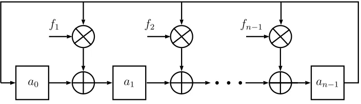
check and cryptography. An LFSR shown in Fig.4.1 is determined with its
charac-teristic polynomial f(x), which is in the form of
f(x) =xn+fn−1xn−1+....+f1x+ 1 (6)
Note in Fig.4.1 that a ⊕ refers to an adder, a ⊗ refers to a multiplier and a
stands for a register. Assume that the registers are loaded with the coefficients of
polynomial A(x) = (a0, a1, ..., an−1). A shift-to-right operation of LFSR is equivalent
to performingA(x)×x modf(x), wherexis the root of its characteristic polynomial
b
f1 f2 fn−1
b
b
a0 a1 an−1
Fig. 4.1: Linear Feedback Shift Register
4.2
Proposed Truncated Polynomial Ring Multiplier
Since the polynomial in truncated polynomial ring requires to take modulo xn−1,
LFSR can be used under truncated polynomial ring.
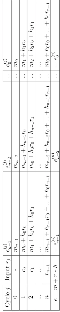
Let the content of registerse0, e1, ..., en−1at clock cyclejbe denoted ase(0j), e (j) 1 , ..., e
(j)
n−1,
respectively. The step to perform truncated polynomial ring multiplication in
hard-ware is presented in Algorithm 4.1.
Algorithm 4.1 Multiplication in Truncated Polynomial Ring
Input: h=h0, ..., hn−1, r =r0, ..., rn−1 Output: e=e0, ..., en−1
1: e(0) = 0
2: for j = 1 to n do 3: for i= 0 ton−1do
4: e(ij) =ei(+1 modj−1) n+hi+1 modn×rj−1 modq 5: end for
6: end for
7: return e=e(n)
We made some modifications to LFSR. An architecture diagram of the proposed
multiplier in truncated polynomial ring is shown in Fig.4.2. It includes n multipliers,
n adders and n registers. Each register can store [log2q] bits. The operations in
NTRUEncrypt are incorporate with modular arithmetic. Sinceq is in the form of 2n, modulo q can be easily achieved by truncated the result to n bits. All the operations
h1
b
hn−1 hn−2 h0
b
b
rn−1, rn−2, ..., r1, r0
en−1 en−2 e0
Fig. 4.2: Proposed Truncated Polynomial Ring Multiplier
Coefficients of operandh(x) = (h0, h1, ..., hn−1) input to each multiplier in parallel,
while coefficients of operand r(x) = (r0, r1, ..., rn−1) input to all the multipliers in a
serial fashion. The registers e(x) = (e0, e1, ..., en−1) are initially loaded with 0. The
registers will store the product h(x)×r(x) mod (xn−1) after n clock cycles.
4.3
Proposed Encryption Architecture
4.3.1 Proposed Modular Arithmetic Unit
During each clock cycle, multiplication is probably the most time consuming operation
in our proposed architecture . As r(x) is always chosen as a ternary polynomial, rj
always has value from {−1,0,1}. This operation can actually be evaluated without
any multiplications. Furthermore, if rj =−1, subtraction operation ei =ei+1 −hi+1
mod q (q= 2n) can be evaluated by
ei =ei+1+hi+1+ 1 (7)
As a result, these operations can be simply calculated with only addition operation
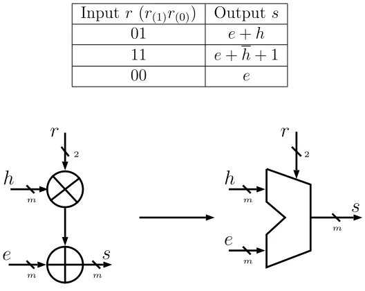
incorporate with modular arithmetic. A proposed Modular Arithmetic Unit (MAU)
Table 4.1: Operations Supported with the Modular Arithmetic Unit
Input r (r(1)r(0)) Outputs
01 e+h
11 e+h+ 1
00 e
m
m m
2 2
m m
m
r
e
s
h
r
e
h
s
Fig. 4.3: Modular Arithmetic Unit
The modulus of MAU is q. The input h, e and output s are encoded in ternary
with m = [log2q] bits. The input r, encoded in two bits r(1)r(0), acts as the control
input. The step to perform operation in hardware is presented in Algorithm 4.2. The
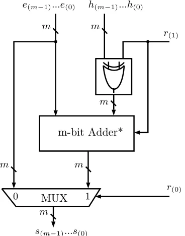
corresponding MAU architecture, which is responsible for performing the operation
in Table 4.1, is shown in Fig.4.4.
Algorithm 4.2 Proposed Modular Arithmetic Unit
Input: e:e(m−1), ..., e(1), e(0) h:h(m−1), ..., h(1), h(0) r :r(1), r(0) Output: s:s(m−1), ..., s(1), s(0)
1: if r(0) = 0 then
2: (s(m−1), ..., s(1), s(0)) = (e(m−1), ..., e(1), e(0)) 3: else {r(0) = 1}
4: (h(m−1), ..., h(1), h(0)) = (h(m−1)⊕r(1)), ...,(h(1)⊕r(1)),(h(0)⊕r(1)); 5: (s(m−1), ..., s(1), s(0)) = (e(m−1), ..., e(1), e(0)) + (hm−1), ...h(1), h(0)) +r(1); 6: end if
r(1)
h(0)
h(1)
h(m−2)
h(m−1)
b
b
b
m
s(m−1)...s(0)
h(m−1)...h(0)
e(m−1)...e(0)
m m
m
m m
b
b
r(1)
r(0)
1
0 MUX
m-bit Adder*
b b b
Fig. 4.4: Proposed Modular Arithmetic Unit
4.3.2 Proposed Encryption Architecture
Operations in encryption:
e(x) = h(x)×r(x) +m(x) modq (8)
Since the random polynomial r(x) has coefficients from {-1,0,1}, the proposed
truncated polynomial ring multiplier and modular arithmetic unit can support the
full operation during encryption. The addition of the message m(x) can be perform
by initial the registers e with coefficients ofm(x). The architecture for encryption is
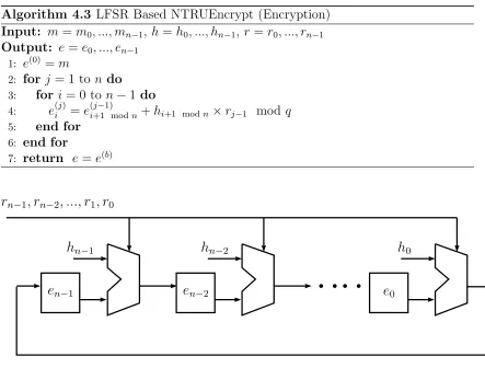
Algorithm 4.3 LFSR Based NTRUEncrypt (Encryption)
Input: m =m0, ..., mn−1, h=h0, ..., hn−1, r=r0, ..., rn−1 Output: e=e0, ..., en−1
1: e(0) =m
2: for j = 1 to n do 3: for i= 0 ton−1do
4: e(ij) =ei(+1 modj−1) n+hi+1 modn×rj−1 modq 5: end for
6: end for
7: return e=e(b)
b b
h
0e
0h
n−2e
n−2h
n−1r
n−1, r
n−2, ..., r
1, r
0b
e
n−1b
Fig. 4.5: LFSR Based NTRUEncrypt (Encryption)
The registers e= (en−1, ..., e1, e0) are initially loaded with m = (mn−1, ..., m1, m0)
in one clock cycle. After n clock cycles, the registers will store the encryption result
e = (en−1, ..., e1, e0). The content of registers at cycle j, j = 0,1, ..., n, is given in
T able 4.2: Register Con ten ts for LFSR Based NTR UEncrypt (Encryption) Cycle j Input rj e ( j ) n − 1 e ( j ) n − 2 ... e ( j ) 0 0 -mn − 1 mn − 2 ... m0 1 r0 m0 + h0 r0 mn − 1 +
hn−
1 r0 ... m1 + h1 r0 2 r1 m1 + h1 r0 + h0 r1 m0 + h0 r0 +
hn−
1 r1 ... m2 + h2 r0 + h1 r1 ... ... ... ... ... ... n
rn−
1
mn
−
1
+
hn−
1 r0 + ... + h0 rn−
1
mn
−
2
+
hn−
2
r0
+
...
+
hn−
1
rn−
1 ... m0 + h0 r0 + ... + h1 rn−
4.4
Proposed Decryption Architecture
We made some adjustment to the algorithm step, so that the Truncated polynomial
ring multiplier can be used within decryption process in hardware. The operations
in decryption are listed as follows:
• a(x) =f(x)×e(x)×fp(x) mod q.
• Shift coefficients of a(x) to the range (−q 2,
q 2)
• b(x) = a(x) mod p
• m(x) = fp(x)×b(x) mod p.
Both the operand f(x) in the first and the operandb(x) in the last step has
coef-ficients from{-1,0,1}. As a result, the proposed truncated polynomial ring multiplier
and modular arithmetic unit can support most of the operations during decryption.
Besides, a design to shift coefficients of a(x) and a modulo a(x) by p is require to
complete the decryption operation. A proposed Modular Unit (MU) is designed
per-formance these operations.
4.4.1 Proposed Modular Unit
The coefficients are required to shift from (0, q−1) to (−q 2,
q
2). In binary form, it can be performed easily by inverting the digits and add one to the result.
Algorithm 4.4 Shift Coefficient Operation
Input: ai
Output: a0i
1: if ai >
q 2 then
2: a0i =−(ai+ 1)
3: else 4: a0
i =ai
Since p is usually chosen as 3 which is a Mersenne number, we can use the
Mersenne primes algorithm to calculate a(x) mod p. And we assume that the
max-imum operand is 1023.
Algorithm 4.5 Modulo 3 Operation
Input: a :a(n−1), ..., a(1), a(0) ,p= 3 Output: m=a mod 3
1: split a into |a(n−1)a(n−2)|a(n−3)a(n−4)|...|a(3), a(2)|a(1), a(0)| 2: b = a(n−1)a(n−2) +a(n−3)a(n−4)+...+a(3)a(2)+a(1)a(0) 3: c = b(3)b(2)+b(1)b(0)
4: m = c(2)+c(1)c(0)
*x(i) represent ith bit of x;
Since the coefficients of a(x) are shifted to (−q 2,
q
2), modulo of a negative number is also required during decryption. A look up table is used to perform both positive
and negative modulo operation and output the result in ternary form {-1,0,1}.
Table 4.3: Look Up Table for Modular Unit
m(2) m(1) m(0) s(1)s(0)
0 0 0 00
0 0 1 01
0 1 0 11
0 1 1 00
1 0 0 00
1 0 1 11
1 1 0 01
1 1 1 00
A circuit to perform both coefficients shift operation and modulo 3 operation is
shown in Fig.4.6. It consists of number of 2-bit full adders and number of 2-bit half
adders. The amount of the units can be varied according to the bit number of the
a
s
b
c
2 2 2 2(a) 2-Bit Full Adder
s
a
b
22
2 (b) 2-Bit Half Adder
b b b b b b b b
0,0
a(m−2)a(m−3)
2
a(n−4)a(n−5)
2
a(1) a(0)
2
a(m−1)
LUT m(1) m(0) s(1) s(0) 2 2 2 2
2 2 2 2
2 2 2 b b b b b b b b m(2)
b b b b b b
b b b
(c) m is an odd number
b b b b b b b b
0,0
0a(m−2)
2
a(n−3)a(n−4)
2
a(1) a(0)
2
a(m−1)
LUT m(1) m(0) s(1) s(0) 2 2 2 2
2 2 2 2
2 2 2 b b b b b b b b m(2)
b b b b b
b b b
4.4.2 Proposed Decryption Architecture
The architecture for encryption is shown in Fig.4.7. which contains ann-bit truncated
polynomial ring multiplier andn modular unit.
b b
e0
a0
en−2
an−2
en−1
fn−1, fn−2, ..., f1, f0
b
an−1
b
MU MU b b b b MU
bn−1 bn−2 b0
Fig. 4.7: LFSR Based NTRUEncrypt (Decryption)
The registersa= (an−1, ..., a1, a0) are initially loaded with 0. It require the circuit
to run twice to complete the decryption procedure. The first round can evaluateb(x)
with inputf(x) ande(x). Then we can recover message by executing the circuit one
more time with input fp(x) and b(x).
4.5
Implementation of Proposed Encryption Architecture
The proposed encryption architecture has been implemented in FPGA. The following
tools were used for the implementation.
• Quartus II Web Edition Software
• ModelSim-Altera software
Cyclone IV EP4CE115F23C7 was chosen as the target device in provided
4.5.1 Implementation Result
The post-synthesis simulation results are shown in Table 4.4 with parameter set
ees401ep1. The encryption speed is fast, in the range of microsecond while the area
consumption remains reasonable.
Table 4.4: Simulation Result for LFSR Based NTRUEncrypt (Encryption)
Resource Latency
#Logic Element 18,049 #Clock Cycle 252
#Registers 3,526 Max Frequency 143.0Mhz
Total Latency 1.76µs
When different sets of parameters are applied to our proposed design, the result
is still satisfactory. The simulation result for different parameter sets are shown in
Table 4.5.
Table 4.5: Simulation Result with Different Parameter Sets
Security
Level Parameter set #LE(S) #RE #CC FMax Latency(T)
112
ees401ep1 18,049 8,826 402 98.86 MHz 4.06µs
ees541ep1 24,349 11,906 542 100.7 MHz 5.38µs
ees659ep1 29,659 14,502 660 90.46 MHz 7.29µs
128
ees449ep1 20,209 9,882 450 103.44 MHz 4.35µs
ees613ep1 27,589 13,490 614 94.23 MHz 6.51µs
ees761ep1 34,249 16,746 762 89.29 MHz 8.53µs
192
ees677ep1 30,469 14,898 678 89.37 MHz 7.58µs
ees887ep1 39,919 19,518 888 86.77 MHz 10.23 µs
ees1087ep1 48,919 23,918 1088 72.42 MHz 15.02 µs
256
ees1087ep2 48,919 23,918 1088 72.42 MHz 15.02 µs
ees1171ep1 52,699 25,766 1172 62.31 MHz 18.80 µs
ees1499ep1 67,460 32,982 1500 72.86 MHz 20.58 µs
4.5.2 Comparison
Our proposed design, along with some other existing works, is implemented using the
• #LE, number of logic elements used by the systems.
• #CC, number of clock cycles required by the systems.
• FMax, the maximum operating frequency of the system.
• Delay, the time requires to encrypt a polynomial.
• S×T, the area-delay product of the systems.
It can be seen from the table that the proposed one has clear advantage over most
works. For example, compared to [35], the proposed one has much higher maximum
frequency and utilizes much shorter time to perform encryption. In comparison of
[36], it has lower resource consumption and higher frequency compared to our design,
however it needs much more clock cycles. It is noted that the number of clock cycles
for [37] (= 113) is optimized for the condition that the maximum distance between
two none-zero coefficient is no more than 8. Nonetheless, the maximum frequency
of [37] is much lower than our design and the resources it needs are nearly 3 times
larger.
Table 4.6: Comparison of Proposed LFSR Architecture with Other Exist Works
For ees401ep1 parameter set
Work #LE(S) #CC FMax Latency(T) S×T
[35] 14,807 402 49.41 MHz 8.13 µs 274.4%
[36] 3,782 3,618 169.49 MHz 21.34 µs 110.1%
[37] 49,001 113 39.91 MHz 2.83 µs 189.2%
Proposed 18,049 402 98.86 MHz 4.06 µs 100.0%
The simulation results in Table 4.6 show that the proposed design outperforms all
the existing works in terms of area-delay product. The new architecture is expected
5
PROPOSED EXTENDED LFSR
ARCHITEC-TURE TO IMPLEMENT NTRUENCRYPT
5.1
General Ideal
The proposed MAU in the last chapter shows that when the control input r, which
is encoded by r(1)r(0), equals to “00” or “10”, the delay required by MAU is Tmux.
Whenr(1)r(0)equals to “01” or “11”, required time equals to Tmux+Tadd+Txor. Thus,
the required time of each clock cycle varies and depends on the input r.
The coefficients of r(x) always have value from {−1,0,1}, which means the input
bits r(1)r(0) only have three states “11”, “00” and “01”. The state “10” is considered
as a redundant state for MAU.
Meanwhile, r(x)∈L(dr, dr) and dr is usually much smaller thann. It is required
to find out how many pairs of “0, 0” coefficients appear consecutively in r(x) to
calculate number of cycles the system can save.
The number of “1” and “−1” coefficients in r(x) is denoted by
n1 =n−1 =dr. (9)
So the number of “0” is
n0 =n−2dr. (10)
The maximum number of “0, 0” pair happen when all of the “0” coefficient appear
consecutively. The number is calculated by
are assigned discontinuously, which is given by
n00min =
0 n1+n−1 ≥n0
(n−4dr)/2 n1+n−1 < n0
(12)
The average number of “0, 0” pair in r(x) is
n00avg =
n00max X
i=n00min (
n1+n−1P
n1+n−1
n1P
n1 ·n−1Pn−1
·n1+n−1+1C
n0−1·
i
X
j=0
n1+n−1+1C
j+1·i−1Cj) (13)
For example, in the parameter setees659ep1, the value ofnis 659, whiledr is equal
to 38. It could be calculated that the number of non-zero coefficients in polynomial
r(x) is 76, while the number of zero coefficients is 583. There are a large number
of zero coefficients contained in polynomial r(x) and many of these zero coefficients
appear consecutively. We can find at least 254 pairs of “0,0” inr(x). And the average
number of “0,0” pair can reach to 273.42. Table 5.3 shows the number of “0,0” pairs
in the polynomial for other parameter sets.
Table 5.1: Number of “0, 0” Pair in Different Parameter Set
Security
Parameter set n #“0” #“0, 0”
Level Avg Min Max
112
ees401ep1 401 176 52.99 0 88
ees541ep1 541 444 199.21 173 222
ees659ep1 659 584 273.42 254 292
128
ees449ep1 449 182 51.83 0 91
ees613ep1 613 504 226.48 197 252
ees761ep1 761 680 318.49 299 340
192
ees677ep1 677 364 126.51 25 182
ees887ep1 887 726 325.84 282 141
ees1087ep1 1087 962 450.70 418 481
256
ees1087ep2 1087 848 370.72 304 424
ees1171ep1 1171 960 431.54 374 480
ees1499ep1 1499 1342 633.68 592 671
pair can be processed in one clock cycle. The proposed method is designed to reduce
the total processing time by deal with a “0, 0” pair within one clock cycle.
5.2
Extended Linear Feedback Shift Register
In order to handle two zero coefficients in one clock cycle, an extended LFSR is
required to perform shifts for both one and two positions. An extended LFSR was
proposed by Wu et al. [38].
Fig. 5.1: Extended Linear Feedback Shift Register
Fig.5.1 shows the structure for both x±1 and x±2 multiplication, which is called
extended LFSR. When the switches are at upper positions, the circuit are configured
to perform x±2 multiplication, which means the contents of the registers are shifted
two positions on their right side. When the switches are at lower positions, the circuit,
which works as a normal LFSR, is shifted one position in each clock cycle. This circuit
can be integrated in our design with minor modification.
5.3
Proposed Extended Modular Arithmetic Unit
Instead of switches, input bits r can be used to control the circuit switch between
m
m m
2
r
e
s
h
m
2
m m
e
h
m
e
′s
r
Fig. 5.2: Extended Modular Arithmetic Unit
Table 5.2: Operations Supported with the Extended Modular Arithmetic Unit
Input r (r(1)r(0)) Outputs
01 e+h
11 e+h+ 1
00 e
10 e0
As compared to previous circuit, an additional input e0 is added to MAU. It
outputs directly when input r is “10”. The truth table of this circuit is given in
table 5.2. As stated before, “10” was a redundant state in previous circuit. In
proposed circuit, this state is assigned to handle the operation for output e0. Four
states of proposed circuit and their output is shown. The details for performing these
operations in hardware is presented in Algorithm 5.1. The inputs of the algorithm is
e, e0, h, r and the output is s. Depending on the control signal r, different operations
Algorithm 5.1 Proposed Extended Modular Arithmetic Unit
Input:
e:e(m−1), ..., e(1), e(0);
e0 :e0
(m−1), ..., e0(1), e0(0);
h:h(m−1), ..., h(1), h(0)
r:r(1), r(0);
Output: s:s(m−1), ..., s(1), s(0); 1: if r(0) = 0 then
2: if r(1) = 0 then
3: (s(m−1), ..., s(1), s(0)) = (e(m−1), ..., e(1), e(0)) 4: else {r(1) = 1}
5: (s(m−1), ..., s(1), s(0)) = (e0(m−1), ..., e0(1), e0(0)) 6: end if
7: else {r(0) = 1}
8: (h(m−1), ..., h(1), h(0)) = (hm−1⊕r(1)), ...,(h(1)⊕r(1)),(h(0)⊕r(1)); 9: (s(m−1), ..., s(1), s(0)) = (e(m−1), ..., e(1), e(0)) + (h(m−1), ...h(1), h(0)) +r(1); 10: end if
*x(i) represtent ith bit of x;
m-bit Adder*
MUX
0 1 r(0)
r(1)
b b
m m
m
m m
e(m−1)...e(0) h(m−1)...h(0)
s(m−1)...s(0)
m
b b b
h(m−1)h(m−2) h(1) h(0)
r(1)
MUX 0 1
m
e′(m−1)...e′(0)
r(1)
b b b
Fig. 5.3: Proposed Extended Modular Arithmetic Unit
The corresponding Extended Modular Arithmetic Unit (EMAU) is shown in Fig.5.3.
com-5.4
Proposed NTRUEncrypt Architecture with Extended LFSR
As presented in previous chapter, operations in encryption is defined as:
e(x) = h(x)×r(x) +m(x) modq (14)
Since the new design can process two consecutive zero coefficient at the same
time, minor modification on input r is required. When two “0” coefficient appear
consecutively in r(x), it should input “10” to the circuit instead of two “00”. n0 is
the coefficient number of r(x) after replace all the “0, 0” pairs with “10’. Algorithm
5.2 shows a typical algorithm to implement ecnryption with EMAU. A corresponding
structure is shown in Fig.5.4.
Algorithm 5.2 Extended Encryption in NTRUEncrypt
Input:
m=m0, ..., mn−1;
h=h0, ..., hn−1;
r=r0, ..., rn0−1; Output: e=e0, ..., en−1;
1: e(0) =m
2: for j = 1 to n0 do 3: if rj−1 = 10 then 4: for i= 0 to n−1 do 5: e(ij) =e(i+2 modj−1) n
6: end for
7: else
8: for i= 0 to n−1 do
9: e(ij) =ei(+1 modj−1) n+hi+1 modn×rj−1 mod q
10: end for
11: end if 12: end for
b
e2
b
b
b
e0
h0
b
en−1
b
hn−1
en−2
hn−2
e1
h1
b
b
rn−1, ..., r1, r0
Fig. 5.4: Extended LFSR Based NTRUEncrypt
The registers e= (en−1, ..., e1, e0) are initially loaded with m = (mn−1, ..., m1, m0)
in one clock cycle. The clock cycles required to encrypt a message depends on the
number of “0, 0” pairs in r(x). The average clock cycle required in encryption for
different parameter sets is shown in Table 5.3. It can be seen that number of clock
cycle #CC is reduced from original required clock cycle n. With a higher security
level, the required clock cycles also increased. More reduced clock cycle can be seen
on higher security level, which means proposed circuit shows more improvements on
more complex parameter set. The content of registers at cycle j, j = 0,1, ..., n0, is
given in Table 5.4.
Table 5.3: Average Clock Cycle for Different Parameter Sets
Security
Level Parameter set n p q dr #CC
112
ees401ep1 401 3 2048 113 350
ees541ep1 541 3 2048 49 343
ees659ep1 659 3 2048 38 387
128
ees449ep1 449 3 2048 134 359
ees613ep1 613 3 2048 55 388
ees761ep1 761 3 2048 42 444
192
ees677ep1 677 3 2048 157 552
ees887ep1 887 3 2048 81 563
ees1087ep1 1087 3 2048 63 638
T able 5.4: Register Con ten ts for Extended LFSR Based NTR UEncrypt Cycle j Input rj e ( j ) n − 1 e ( j ) n − 2 ... e ( j ) 0 0 -mn − 1 mn − 2 ... m0 1 r0 m0 + h0 r0 mn − 1 +
hn−
1 r0 ... m1 + h1 r0 2 r1 m1 + h1 r0 + h0 r1 m0 + h0 r0 +
hn−
1 r1 ... m2 + h2 r0 + h1 r1 3 r2 =“10” m3 + h3 r0 + h2 r1 + h1 r2 + h0 r3 m2 + h2 r0 + h1 r1 + h0 r2 +
hn−
1 r3 ... m4 + h4 r0 + h3 r1 + h2 r2 + h1 r3 ... ... ... ... ... ... n 0 rn 0− 1 mn − 1 +
hn−
1 r0 + ... + h0 rn 0− 1 mn − 2 +
hn−
2
r0
+
...
+
hn−
5.5
Implementation of Proposed Encryption Architecture
The proposed architecture also has been implemented in FPGA for performance
ver-ification. The following tools were used for the implementation.
• Quartus II Web Edition Software
• ModelSim-Altera software
Cyclone IV EP4CE115F23C7 was chosen as the target device in provided
imple-mentation.
5.5.1 Implementation Results
The simulation results with various parameter sets are shown in Table 5.5. It can be
seen from the table that with the increasing of security level, the operation frequency
of the circuit gradually decreases in an acceptable range. More logic elements and
registers are also required.
Table 5.5: Simulation Result with different Parameter Set (Extended LFSR)
Security
Level Parameter set #LE(S) #RE #CC FMax Latency(T)
112
ees401ep1 22,460 8,826 350 97.36 MHz 3.58µs
ees541ep1 30,300 11,906 343 94.58 MHz 3.62µs
ees659ep1 36,908 14,502 387 81.12 MHz 4.77µs
128
ees449ep1 25,148 9,882 359 92.29 MHz 3.88µs
ees613ep1 34,332 13,490 388 85.02 MHz 4.56µs
ees761ep1 42,620 16,746 444 75.36 MHz 5.89µs
192
ees677ep1 37,916 14,898 552 89.18 MHz 6.18µs
ees887ep1 49,676 19,518 563 87.42 MHz 6.44µs
ees1087ep1 60,876 23,918 638 73.71 MHz 8.65µs
256
ees1087ep2 60,876 23,918 718 73.71 MHz 9.74µs
ees1171ep1 65,581 25,766 741 84.07 MHz 8.81µs
5.5.2 Comparison
Table 5.6: Comparison between LFSR Structure and Extended LFSR Structure
Security
Level Parameter set
LFSR Extended LFSR
#LE(S) Latency(T) #LE(S) Latency(T)
112
ees401ep1 18,049 4.06µs 22,460 (24.4%) 3.58 µs(11.8%) ees541ep1 24,349 5.38µs 30,300 (24.4%) 3.62 µs(32.7%) ees659ep1 29,659 7.29µs 36,908 (24.4%) 4.77 µs(34.5%)
128
ees449ep1 20,209 4.35µs 25,148 (24.4%) 3.88 µs(10.8%) ees613ep1 27,589 6.51µs 34,332 (24.4%) 4.56 µs(29.9%) ees761ep1 34,249 8.53µs 42,620 (24.4%) 5.89 µs(30.9%)
192
ees677ep1 30,469 7.58µs 37,916 (24.4%) 6.18 µs(18.4%) ees887ep1 39,919 10.23 µs 49,676 (24.4%) 6.44 µs(37.0%) ees1087ep1 48,919 15.02 µs 60,876 (24.4%) 8.65 µs(42.4%)
256
ees1087ep2 48,919 15.02 µs 60,876 (24.4%) 9.74 µs(35.1%) ees1171ep1 52,699 18.80 µs 65,581 (24.4%) 8.81 µs(53.1%) ees1499ep1 67,460 20.58 µs 83,949 (24.4%) 13.62 µs(33.8%)
A comparison between the previous LFSR structure and the extended LFSR structure
is listed in Table 5.6. The logic elements required by the extended LFSR structure
are 24.4% larger than the LFSR structure. Because of the reduction on clock cycle,
the extended LFSR structure can save at least 10.8% time with 128 security level and
ees449ep1 parameter set. The improvement can be up to 53.1% with 256 security
level and ees1171ep1 parameter set. The simulation results in Table 4.6 show that the
proposed design outperforms all the existing works in terms of area-delay product.
The extended architecture is expected to be used for a system with higher speed
requirement.
5.6
Discussion on Parameter Selection in Hardware
Imple-mentation
A parameter set generation algorithm (Section 2.3.1) is required to generate parameter
set according to different cost metrics. To obtain the best performance in hardware
is derived from the convolution times for a parameter set costspeed =n·df. But for
hardware implementation in my previous work, a clock cycle is always required to
handle a zero-coefficient or a non-zero coefficient. So that at previous work, the value
of speed cost function of hardware is n2. For the proposed work in this chapter, as
stated before, consecutive “0” only requires one clock cycle. Thus, it can be derived
that the cost function becomes
costspeed=n·(n−n00), (15)
which is from the original cost function reduced by number of consecutive “0, 0”.
Referring to (12), the worst case of number of n00 is (n−4dr)/2. Substituting the
value ofn00 to (15), we get
costspeed=
n2 n
1+n−1 ≥n0
n·(n/2 + 2df) n1+n−1 < n0
. (16)
6
PROPOSED SYSTOLIC ARRAY
ARCHITEC-TURE TO IMPLEMENT NTRUENCRYPT
6.1
Systolic Array
A systolic system is a network of processors which rhythmically compute and pass
data through the system. It is first proposed by H.T. Kung and C.E. Leserson in
1979 [39]. Physiologists use the work ‘systole’ to refer to the rhythmically recurrent
contraction of the heart and arteries which pulses blood through the body. In a
systolic computing system, the function of a processor is analogous to that of the
heart. Every processor regularly pumps data in and out, each time performing some
short computation, so that a regular flow of data is kept up in the network. Systolic
architecture can result in cost-effective , high-performance special-purpose systems
for a wide range of problems.
Systolic systems consists of an array of processing elements (PE) processors are
called cells, each cell is connected to a small number of nearest neighbours in a mesh
like topology. Each cell performs a sequence of operations on data that flows between
them. Generally the operations will be the same in each cell, each cell performs an
operation or small number of operations on a data item and then passes it to its
neighbour. Systolic array is a computing network possessing include the following
property [40]:
• The design makes multiple use of each input data item
Because of this property , systolic systems can achieve high throughputs with
modest I/O bandwidths for outside communication.
• The design uses extensive concurrency
Concurrency can be obtained by pipelining the stages involved in the
both.
• There are only a few types of simple cells
To achieve performance goals, a systolic system is likely to use a large number
of cells which must be simple and of only a few types to curtail design and
implementation cost.
• Data and control flow are simple and regular
Pure systolic system totally avoid long-distance or irregular wires for data
com-munication.
Systolic arrays can be used to build many cost-effective, high-performance
special-purpose system, such as matrix multiplication, polynomial evaluation, convolution
and image processing.
6.2
Algorithm
As we mention in the previous chapter, operations in encryption is defined as:
e(x) = m(x) +h(x)×r(x) = en−1xn−1+....+e1x+e0
where
ek =mk+ P
i,j=0,1,...,n−1
i+j=k modn
hirj,k = 0,1, ..., n−1
Since all polynomials are taken modulo xn−1, the degree exceed N-1 should be
truncated, which means the powerxn should be replaced by 1, the powerxn+1 should
be replaced by x, and so on. Also because of each partial product term is reduced
modulo q, there is no carry propagation across the column. In Fig.6.1, e(x), m(x),
hn−1 hn−2 hn−3 b b b h
2 h1 h0
rn−1 rn−2 rn−3 b b b r
2 r1 r0
×
hn−1r0 hn−2r0 hn−3r0 b b b h
2r0 h1r0 h0r0 hn−2r1 hn−3r1 hn−4r1 b b b h
1r1 h0r1 hn−1r1
hn−3r2 hn−4r2 hn−5r2 b b b h
0r2 hn−1r2 hn−2r2
b b b b b b b b b b b b b b b b b b
h2rn−3 h1rn−3 h0rn−3 h5rn−3 h4rn−3 h3rn−3
h1rn−2 h0rn−2 hn−1rn−2 h4rn−2 h3rn−2 h2rn−2 h0rn−1 hn−1rn−1 hn−2rn−1 h3rn−1 h2rn−1 h1rn−1 +
b b b
b b b
b b b
en−1 en−2 en−3 b b b e
2 e1 e0
mn−1 mn−2 mn−3 b b b m
2 m1 m0
mn−1 mn−2 mn−3 b b b m
2 m1 m0
+
Fig. 6.1: Encryption Operation in Vertical Form
6.3
Proposed NTRUEncrypt Architecture with Systolic
Ar-ray
In Fig.6.1, you can see that beside the first row, every cell of the array is a
multi-plication operation. The coefficients ei can be calculated by accumulate the product
of each cell in each column and add mi. This parallel nature property makes this
algorithm ideally suitable for use in systolic array architecture.
Also because of each column is independent of the other, the same result can be
obtain if we only change the order of the elements of each column. We make some
![Table 2.1: Recommended Parameters for NTRUEncrypt [1]](https://thumb-us.123doks.com/thumbv2/123dok_us/1398505.1172563/27.612.155.491.150.359/table-recommended-parameters-for-ntruencrypt.webp)
![Table 2.2: Parameters for Revised NTRUEncrypt [2]](https://thumb-us.123doks.com/thumbv2/123dok_us/1398505.1172563/30.612.199.444.293.358/table-parameters-for-revised-ntruencrypt.webp)