18th International Conference on Structure Mechanics in Reactor Technology (SMiRT 18) Beijing, China, August 7-12, 2005 SMiRT18-G02-5
DOUBLE CRACKING IN BRITTLE CYLINDRICAL SPECIMENS
SUBJECTED TO QUENCHING
Weijing He, Haiyan Li, Siu-Lun Fok
∗, J. Derek Jackson, Jan R. Wright
Nuclear Graphite Research Group
School of Mechanical, Aerospace and Civil Engineering, The University of
Manchester
Manchester M13 9PL, U.K.
Tel: 44-(0)-161-2754327, Fax: 44-(0)-161-2754328, [email protected]
Abstract
Hollow cylindrical specimens made of the ceramic material, Pyrophyllite, were subjected to quench tests in water. The specimens fractured in a consistent manner with two diametrically opposite longitudinal cracks. Finite element analysis indicates that the primary crack occurred at the stage when the strain energy of the cylinder reached its maximum during the thermal transient process, while the secondary crack was caused by stress waves generated following the primary crack. Experimental observation of the time of fracture and examination of the crack morphology support the numerical predictions. The work reported here may help to shed light on the fracture criterion for brittle cylindrical components under transient thermal and dynamic loadings.
Keywords
Dynamic stress waves, double cracking, brittle materials, cylindrical specimens, quenching, finite element analysis, stress amplification
1 Introduction
Components in nuclear reactors can be subjected to both thermal and mechanical loading, which might cause them to fracture in an unstable manner if the material is inherently brittle or becomes so through irradiation embrittlement. Furthermore, stress waves created by the initial or primary cracking might cause further fractures in such components.
Miklowitz was among the first workers to point out that multiple cracking in brittle materials was the result of dynamic stress waves generated by the primary fracture (Ref. 1). The geometry he investigated was a rod under tension. This was followed by the work of Shindler and Kolsky who also demonstrated multiple cracking in brittle rods under four-point bending (Ref. 2).
The question arises as to whether multiple cracking resulting from dynamic stress waves could be produced by thermal, rather than mechanical, loading. In an attempt to answer this question, quench tests have been carried out to induce cracking in brittle hollow cylinders. Dynamic F.E. analysis has also been performed to help explain the experimental observations. The results could be of value in assessing the behaviour of cylindrical reactor components subjected to high thermal loading.
2 Experiments
2.1 Method
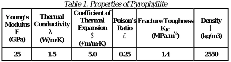
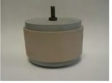
The machinable ceramic material, Pyrophyllite, was used in this study. Its properties are given in Table 1. Cylindrical specimens made from this material were heated to temperatures up to 800°C in a furnace and then quenched in a cold water bath to suddenly impose an outer surface temperature of 100°C. As shown in Fig. 1, the bore of each specimen was sealed by two end caps to prevent water from reaching the inner surface, thus ensuring that the cooling occurred on the outer surface only. The caps were tied together using a nut and bolt arrangement with a slightly loose fit to avoid undue compressive stresses in the cylinder.
Table 1. Properties of Pyrophyllite
Young’s Modulus E (GPa) Thermal Conductivity (W/m·K) Coefficient of Thermal Expansion α (µm/m·K)
Poison’s Ratio
υ
Fracture Toughness KIC
(MPa.m½)
Density ρ (kg/m3)
25 1.5 5.0 0.25 1.4 2550
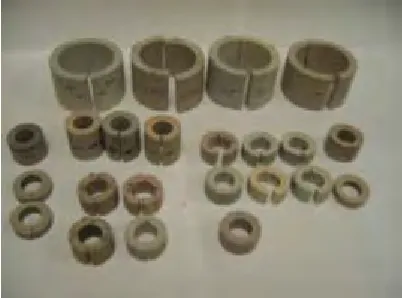
A variety of specimens with different dimensions and geometries were used in the quench tests. Axial V-grooves were machined onto the surface of some of the specimens to investigate the effect of localized stress concentration; see, for example, Fig. 2. The approximate depth of each groove was 1 mm. Details of the specimens tested are summarized in Table 2.
Table 2. Details of quench test specimens
ID (mm) OD (mm) Length (mm) Number of grooves
Number of specimens
20 36 10 1 1
20 36 20 1 1
20 36 20 8 11
20 36 40 8 3
60 80 50 1 2
Fig. 1. Sealing arrangement for quench test specimen (dimensions in mm)
a). Cylindrical specimen without axial grooves (ID = 60 mm, OD = 80 mm)
b). Cylindrical specimen with axial grooves at 45° intervals (ID = 20 mm, OD = 30 mm)
Fig. 2. Assembled quench test specimens of different geometries and dimensions
2.2 Results
Fracture of the cylinders occurred a few seconds after they were immersed in the water bath. However, it was necessary to preheat the specimens to a high temperature (800°C) to cause fracture to take place. Some of the specimens which had been heated to a lower temperature survived the quenching without visible fracture.
When the specimens fractured, almost all of them did so with two apparently simultaneous longitudinal cracks which were diametrically opposite (see Figs. 3 and 4). The only exception was the specimen shown in Fig. 5 which had the two cracks approximately 90° from each other. No further cracks were evident on the cylinders. Where there were grooves present in a specimen, at least one of the cracks would run along the tip of a groove.
Fig. 3. Pyrophyllite specimens fractured by quenching
a). Double cracking of cylindrical specimen without grooves
b). Double cracking of cylindrical specimen with grooves
Fig. 4. Pyrophyllite specimens fractured with two diametrically opposite cracks
3 F.E. analysis
ABAQUS (Ref. 6) was used to perform the F.E. analysis. Two-dimensional F.E. models were created for both grooved and ungrooved specimens. Figure 6a shows the model for a hollow cylinder without grooves whose inner diameter was 20 mm and outer diameter 30 mm. Figure 6b shows the model having the same diameters but with eight equally spaced V-grooves, each of 1 mm depth.
The same mesh was used for both the thermal and dynamic analyses. Eight-node, bi-quadratic, diffusive heat transfer elements were used for the transient thermal analysis (quenching) while eight-node, bi-quadratic, generalized plane-strain elements with reduced integration were used for the dynamic analysis following primary cracking.
a). FE model of hollow cylindrical specimen without grooves
b). FE model of hollow cylindrical specimen with grooves
Fig. 6. FE models used in FE dynamic analysis
(arrows indicate paths along which results are sampled)
Possible coupling between the thermal and dynamic behaviors of the system and the interaction between the cylinder and the surrounding water were not considered. The justification for this simplification will be given later. Thus, the transient temperature fields and the resulting thermal stresses in the transient were established first. The latter were then used as initial conditions for the subsequent dynamic analysis following primary cracking.
Dual coincident nodes were provided along a through-thickness radial line to allow modeling of the primary crack. These were tied together, using appropriate boundary conditions, during the thermal transient analysis and the initial stressing of the cylinder prior to primary cracking. For the grooved specimen, the primary crack was assumed to initiate from one of the groove tips. To simulate primary cracking, the boundary conditions holding together the dual coincident nodes were released instantaneously and the sudden release of strain energy generated stress waves that travelled round the ‘C-ring’ formed after the primary cracking. The interaction of these stress waves with the initial quasi-static thermal stresses was an important factor when considering whether secondary cracking could occur.
3.1 Transient thermal analysis
For the transient thermal analysis, the initial temperature of the specimen was set to be uniform at 800°C. The outside temperature was then decreased to 100°C instantaneously to simulate quenching in a water bath. The inner surface was assumed to be fully insulated throughout the process.
the very high thermal gradient there. As time progressed, a more linear stress distribution across the thickness began to develop, which gradually disappeared as the temperature profile became more uniform.
Similar results were obtained for the grooved specimen; see Fig. 8.
a). Through-thickness temperature distribution in cylindrical specimen without grooves
b). Through-thickness thermal hoop stress distribution in cylindrical specimen without grooves
Fig. 7. Transient temperature and thermal stress distributions in a cylinder without grooves
a). Through-thickness temperature distribution in cylindrical specimen with grooves
b). Through-thickness thermal hoop stress distribution in cylindrical specimen with grooves
Fig. 8. Transient temperature and thermal stress distributions in a cylinder with grooves
3.2 Dynamic analysis following primary cracking
The exact condition for, and hence the precise moment of, the initiation of the primary crack was not certain. Therefore, different initiation times were assumed for the primary crack. Thermal stress fields extracted from the thermal transient analysis at different times during the thermal transient were used as initial conditions for the dynamic analysis. By comparing the resulting dynamic responses, focusing in particular on the position of peak stress amplification, with the observed secondary crack position, the approximate initiation time for primary cracking was inferred.
position observed in experiment, if the primary crack is assumed to occur at 2 s or more into the quenching process (Figs. 9b-d). Figure 10 shows the positions on the cylinder corresponding to the two main stress peaks in the time histories. The results for the peak stress amplification are further summarized in Table 3.
a). t = 0.5s b). t = 2s
c). t = 5s d). t = 10s
1 2 3
4 5
6
Fig. 10. Positions of stress peaks on cylinder
Time of Assumed Primary Cracking (s)
Position of Peak Stress Amplification
Magnitude of Peak Stress Amplification
0.5 90o 1.24
2 90o, 180o 1.38
5 180o 2.1
10 180o 2.5
20 180o 2.88
Table 3. Position and magnitude of peak stress amplification assuming different initiation
times for primary cracking
Similar results were again obtained for the cylinder with grooves. However, in this case, stress sampling must be avoided at the groove tip position where a stress singularity exists.
4 Discussion
It is almost certain that the primary crack would initiate from a V-groove, if present, since the thermal stresses were highest on the outer surface and they would be further enhanced by the stress concentrating V-groove. Some of the specimens had one of the cracks not running through the particular V-groove even though it was in the close vicinity. These were considered to be the secondary cracks and their morphology suggested that they had initiated from the inner surface.
The F.E. analysis indicated that, for secondary cracking to occur at 180° from the primary crack, the latter must initiate at least 2 s after the start of quenching. Also, the secondary crack was predicted to initiate from the inside of the cylinder. Both of these predictions were in accord with experimental observations. It follows that the maximum stress failure criterion may not be strictly applicable to the onset of primary cracking in cylinders subjected to quenching, since the hoop stress on the outer surface was highest right at the beginning of quenching and yet fracture did not occur immediately. Alternative failure criteria need to be considered.
Figure 11 shows the change in the total strain energy of the cylinder during the thermal transient. It can be seen that, starting from zero, the total strain energy reaches its maximum value at about 4 s into quenching, i.e. the approximate time observed in the experiments when cracking took place and the time required by the numerical prediction for primary cracking to occur in order to produce diametrically opposite double cracks. Thus, it seems reasonable to conclude that primary cracking in cylindrical specimens subjected to quenching occurs when the total strain energy reaches a critical value. Since the maximum strain energy is proportional to the heating temperature, this also explains why the cylinders needed to be heated to a sufficiently high temperature before cracking could take place, even though stresses much higher than their static strength could be achieved with a lower heating temperature.
a). Total strain energy in ungrooved hollow cylindrical specimen
b). Total strain energy in grooved cylindrical specimen
Fig. 11. Time history of total strain energy of cylinders during thermal transient
Similarly, the maximum stress failure criterion does not seem to be applicable to the onset of secondary cracking either. From Fig. 9, it can be seen that dynamic stresses much higher than the static strength of the material had occurred earlier in the time history at positions other than the inner surface 180° from the primary crack, and yet only one out of the twenty-four specimens tested did not fracture with diametrically opposite cracks.
There was, though, a relatively small stress peak on the outer surface, 180° from the primary crack, which occurred right at the start of the time history; see Fig. 9. However, given that the secondary crack morphology indicated that it had initiated from the inner surface, this small stress peak was considered not to be responsible for secondary cracking.
the water may have prevented further cracking from taking place, such as the multiple cracks observed in the internal pressure tests (Refs. 3 and 4).
The work presented in this paper represents only a preliminary analysis of the quench test results. Additional work, both experimental and numerical, is required to further verify the theory proposed for the double cracking of cylindrical specimens subjected to thermal loading. Experimentally, the use of thermal loading in a dry environment which allows more data, such as cylinder temperature and strains, to be gathered would help to pinpoint the exact moment and position of both primary and secondary cracking. It is also important to test other brittle materials to see whether double cracking can be reproduced using them. The use of fracture mechanics analysis would shed more light on the onset of cracking and thus help to formulate a fracture criterion for brittle materials under transient and dynamic loadings.
5 Conclusions
• Hollow cylindrical specimens made of Pyrophyllite mainly fractured with two diametrically opposite cracks along the longitudinal axis when they were subjected to quenching.
• The lack of other fracture patterns indicates a systematic mechanism linking the two cracks.
• The primary crack seemed to occur at the stage when the total strain energy of the cylinder reached a critical value.
• Examination of the crack morphology indicated that the secondary crack was initiated at the inner surface of the cylinder.
• The occurrence of the secondary crack can be explained by stress amplification due to dynamic loads generated following primary crack.
Acknowledgements
The financial support of the UK Health and Safety Executive for this work is gratefully acknowledged. The views expressed in this paper are those of the authors and do not necessarily represent the views of the Health and Safety Commission/Executive.
Reference
1. Miklowitz J, Elastic waves created during tensile fracture – phenomenon of a second fracture, J Appl Mech 20 (1952), 122-130.
2. Shindler HJ and Kolsky H, Multiple fractures produced by the bending of brittle beams, J Mech Phys Solids 31 (1983), 427-437.
3. Sato Y and Hashimoto A, Failure of hollow cylinders of brittle materials under internal gas pressure, J Mater Sci Soc Jpn 20 (1983), 59-65 (in Japanese).
4. Sato Y and Hashimoto A, The fracture of hollow cylinders of brittle materials under dynamic internal gas pressure, Trans Jpn Soc Mech Eng A 52 (1986), 1290-1294 (in Japanese).
5. Kuroda M, Fok SL, Marsden BJ and Oyadiji SO, Analyses of the multiple cracking behaviour of brittle hollow cylinders under internal pressure, Int J Impact Eng, in press.