Effect of Microstructure on Stress Corrosion Cracking of Alloy 600 and Alloy 690 in
Caustic Solution
Kim Hong Pyo 1), Park Jung Kyu 2), Lim Yun S o o I) and Kim Joung S o o 1) 1) Korea Atomic Energy Research Institute, Taejon, Korea
2) Dept. Metallurgical Engineering, ChungNam University, Taejon, Korea
A B S T R A C T
Stress corrosion cracking of Alloy 600 and Alloy 690 has been studied with a C-ring specimen in 10% and 40% NaOH at 315°C. SCC test was performed at 200mV above corrosion potential. Initial stress on the apex of C-ring specimen varied from 100 to 250% of yield strength. Solution annealed(SA) specimen was prepared by heat treatment at 1100°C for 30min followed by water quench. Sensitization treatment was performed at 600°C for 24 Hrs and thermal treatment(TT) at 715°C for 15Hrs. Sensitized Alloy 600 is more resistant to SCC compared to SA Alloy 600, suggesting that a beneficial effect of intergranular carbide prevail over harmful effect of Cr depletion around a grain boundary. Generally, SCC resistance of Alloy 600 increases in both 10% and 40% NaOH solution as the coverage of an intergranular carbide, defined as sum of an intergranular carbide length divided by grain boundary length, increases if the grain size of the Alloy 600s are almost same. Low temperature mill annealed Alloy 600 with small grain size and without intergranular carbide is most susceptible to SCC. SCC resistance of Ni-zCr-10Fe alloy also increases in both 10% and 40% NaOH solution as the Cr content of the alloy increases if the density of an intergranular carbide are almost same. So, TT Alloy 690 is most resistant to SCC. An empirical relationship of SCC rate with stress and NaOH concentration is developed.
INTRODUCTION
Alloy 600 has been used as steam generator tubings in nuclear power plant because it has excellent corrosion resistance in primary and secondary coolant. But the Alloy 600 has undergone degradation such as intergranular attack and intergranular stress corrosion cracking(SCC) in the roll transition, U bend and tube to tube support plate intersection[ 1-3]. Failure analysis of pulled out tubes and results of hideout tests indicated that the caustic environment in the crevice was responsible for most of the intergranular attack and intergranular SCC of steam generator tubing materials[4].
Extensive research has been done to improve SCC resistance of steam generator tubings. High temperature mill annealed(HTMA) materials with intergranular carbide and large grain size showed better resistance to SCC than low temperature mill annealed(LTMA) materials with intragranuar carbide and small grain size[5]. Thermal treatment(TT) producing semicontinuous intergranular carbide was reported to be beneficial to SCC resistance in primary water[6] and 10% NaOH[7]. Because SCC crack propagates along grain boundary, grain boundary chemistry has a critical influence on SCC resistance of Alloy 600 in caustic solution. Grain boundary chemistry can be viewed in terms of intergranular carbide distribution, Cr depletion around grain boundary and segregation of minor alloying element, C and impurities such as P, S and B into grain boundary. However relative contribution microstructural features to SCC is not clearly identified in caustic
SMiRT 16, Washington DC, August 2001 Paper # 1095
environment.
LTMA Alloy 600, HTMA Alloy 600 and TT Alloy 600 are still used for steam generator tubing of many operating
nuclear power plants. TT Alloy 690 is being used as a steam generator tubing of new and replaced steam generator of nuclear
power plants. For life prediction and timely maintenance of nuclear power plant, it is very important to identify effect of
environmental and mechanical parameter on SCC process.
The purpose of this work is to evaluate the effect of microstructure, stress and NaOH concentration on SCC in
caustic solution
E X P E R M E N T A L P R O C E D U R E
Their chemical compositions are shown in Table 1. Four heats of HTMA Alloy 600s tubing, used in nuclear power
plants, were provided by three tube manufacturers. Heat treatment of the HTMA Alloy 600A and TT Alloy 690 and their
designation are shown in Table 2.
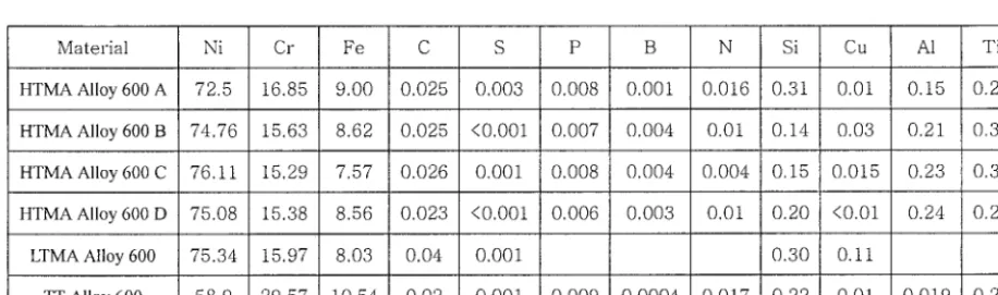
Table 1. Chemical Composition of Materials.
Material Ni Cr Fe C S P B N Si Cu A1 Ti
HTMAAIIoy 600 A 72.5 16.85 9.00 0.025 0.003 0.008 0.001 0.016 0.31 0.01 0.15 0.28
HTMAAIloy 600 B 74.76 15.63 8.62 0.025 <0.001 0.007 0.004 0.01 0.14 0.03 0.21 0.34
HTMAAIloy600C 76.11 15.29 7.57 0.026 0.001 0.008 0.004 0.004 0.15 0.015 0.23 0.32
HTMAAIloy600D 75.08 15.38 8.56 0.023 <0.001 0.006 0.003 0.01 0.20 <0.01 0.24 0.26
LTMAAlloy 600 75.34 15.97 8.03 0.04 0.001 0.30 0.11
TTAlloy 600 58.9 29.57 10.54 0.02 0.001 0.009 0.0004 0.017 0.22 0.01 0.019 0.26
Carbide distribution of Alloy 600 was examined by electrolytic etching at 2.5~3V for 15~30sec in orthophosphoric
acid and grain boundary being evaluated by electrolytic etching at 2.5~3V for 15~30sec in nital. Alloy 600 and Alloy 690 were also chemically etched in bromine for 15sec for carbide examination. A modified Huey test was carried out in boiling
25%HNO3 for 48Hrs.
The 10% and 40% NaOH solutions were prepared by adding reagent grade NaOH to demineralized the water.
Reference electrode and counter electrode were an external Ag/AgC1 electrode and Pt wire, respectively. All the values of
electrode potential were relative to that of external Ag/AgC1 electrode unless otherwise indicated.
The SCC test was conducted in 10% and 40% NaOH using C-ring specimen at 315°C. The C-ring specimen was
held at 200mV above corrosion potential. The stress at the apex of the C-ring specimen was varied from 150% to 250% of
room temperature yield strength by changing outer diameter displacement of the C-ring. The SCC fracture surface and cross-
Table 2. Heat Treatment and Designation of Alloy.
SA Alloy 600 SASEN Alloy 600 SATT Alloy 600 HTMA Alloy 600 HTMASEN Alloy 600 HTMATT Alloy 600 SA Alloy 690 TT Alloy 690
solution annealed at 1100°C for 30min and then water quenched(SA) sensitized at 600°C for 24Hrs following SA
thermally treated at 715°C for 15Hrs following SA commercially high temperature mill annealed sensitized at 600°C for 24Hrs following HTMA thermally treated at 715°C for 15Hrs following HTMA
solution annealed at 1150°C for 30min and then water quenched thermally treated at 720°C for 10Hrs
RESULTS A N D D I S C U S S I O N
Microstructure
Four heats of HTMA Alloy 600s tubing have similar intergranular carbide distribution, Cr and C content, grain size and mechanical properties as shown in Table 3.
Table 3. Metallurgical Characteristics and Mechanical Properties of HTMA Alloy 600s.
Alloy
HTMA Alloy 600A HTMA Alloy 600B HTMA Alloy 600C HTMA Alloy 600D
ASTM Grain Size No.
5.0 5,0 6.0 5.5
Intergranuar Carbide Distribution discontinuous discontinuous discontinuous discontinuous
Yield Strength (ksi) 41.4 35.5 37.1 37.7
Tensile Strength (ksi) 98.8 94 97.1 95.5
Elongation(%)
43 46 44 43.5
HTMA Alloy 600 and it's average length and thickness are larger than those of HTMA. Intergranular carbide in HTMATT Alloy 600 is about 2urn and longer than that in HTMASEN Alloy 600. Intergranular carbide spacing in HTMATT Alloy 600 is about 0.2urn and more closely spaced than that in HTMASEN Alloy 600. All boundary except twin boundary has intergranular carbides. The extent of variation in intergranular carbide length and their spacing for HTMATT Alloy 600 is least among Alloy 600s used in this work. Intergranular carbide in TT Alloy 690 is about 0.45~tm long and their spacing is about 0.02jam.
Table 4. Intergranular Carbide Length, Thickness and a Fraction of Intergranular Carbide in Grain Boundary.
Alloy
HTMA Alloy 600 HTMASEN Alloy 600 HTMATT Alloy 600 TT Alloy 690
Intergranular Carbide Length(~tm)
0.28 0.41 0.57
Intergranular Carbide Thickness(~tm)
0.15 0.20 0.29
0.45 0.15
Coverage of Intergranular Carbide in Grain Boundary(%)
28 80 89 96
The degree of Cr depletion around grain boundary measured with Modified Huey test is shown in Table 5. Precipitation of intergranular carbide simultaneously produces Cr depletion around grain boundary. But the Cr depletion around grain boundary is healed by Cr diffusion from matrix back into the grain boundary if heat treatment temperature and time is high and long enough. SA Alloy 600 shows a very slight weight loss because it is cooled too fast from solution anneal temperature to room temperature to precipitate intergranular carbide. SASEN Alloy 600 shows significant weight loss because of extensive precipitation of intergranular carbide and concurrent Cr depletion around grain boundary. SATT Alloy 600 shows much less weight loss compared to SASEN Alloy 600 because heat treatment temperature is high enough for Cr diffusion from matrix back to the Cr depleted grain boundary. HTMA Alloy 600 shows greater weight loss than SA Alloy 600 because it has intergranular precipitate produced during cool down from mill anneal temperature to around 500°C. HTMASEN Alloy 600 and HTMATT Alloy 600 are similar to SASEN Alloy 600 and SATT Alloy 600 in weight loss, respectively because heat treatments are same after solution anneal or mill anneal.
Stress Corrosion Cracking
following order : SA Alloy Alloy 600, SASEN Alloy 600 and SATT alloy 600. Grain size of SA Alloy 600, SASEN Alloy 600 and SATT alloy 600 are almost same because heat treatment at 600°C after mill anneal is not high enough for grain growth to occur. Maximum SCC rate of HTMA Alloy 600, HTMASEN Alloy 600 and HTMATT alloy 600 in 10% NaOH and 40% NaOH at 315°C is shown in Table 7. Maximum SCC rate decrease with a following order in 10% NaOH and 40% NaOH: HTMA Alloy 600, HTMASEN Alloy 600 and HTMATT alloy 600. Grain size of HTMA Alloy 600, HTMASEN Alloy 600 and HTMATT alloy 600 are almost same. Because SCC crack propagates along the grain boundary, grain boundary chemistry has critical influence on SCC resistance of Alloy 600 in caustic solution. Grain boundary chemistry can be viewed in terms of intergranular carbide distribution, Cr depletion around grain boundary and segregation of minor alloying element, C and impurities such as P, S and B into the grain boundary.
Table 5. Weight Loss Measured in Boiling HNO3 for 48Hrs (Modified Huey test).
Alloy Weight loss(kg/m2/sec)
SA Alloy 600
20x10 -9
SASEN Alloy 600 627x10 9
SATT Alloy 600
18×10 -9
HTMA Alloy 600
l15x10 -9
HTMASEN Alloy 600
HTMATT Alloy 600 22x10 -9
*: completely disintegrated
Table 6 Maximum SCC Rate of SA Alloy 600, SASEN Alloy 600 and SATT Alloy 600 in 40% NaOH at 315°C and at a Initial Stress of 150% YS
Alloy SA Alloy 600 SASEN Alloy 600 SATT Alloy 600
Maximum SCC Rate(m/sec) 4.8x 10 .9 4.0x 10 .9 0.7x 10 .9
Table 7 Maximum SCC Rate of HTMA Alloy 600, HTMASEN Alloy 600 and HTMA TT Alloy 600 with a Initial Stress of 250% of YS in 10% and Those with a Initial Stress of 150% of YS in 40% NaOH at 315°C.
HTMA HTMA SEN HTMA TT
Alloy Alloy 600 Alloy 600 Alloy 600
Maximum SCC Rate(m/sec) in 10% NaOH 1.7x 10 .9 1.3x 10 1° 7.7x 10 1°
Maximum SCC Rate(m/sec) in 40% NaOH 5.4 x 10 .9 3.1 x 10 -9 0.6x 10 .9
work is long enough to rule out effect of segregation on SCC.
The big difference of SA Alloy 600 and SATT Alloy 600 in grain boundary chemistry is the presence of intergranular carbide in SATT Alloy 600 since SA Alloy 600 has no intergranular carbide. So, higher resistance of SATT Alloy 600 than SA Alloy 600 can be attributed to the presence of intergranular carbide in SATT Alloy 600. SA Alloy 600 is more susceptible to SCC than SASEN Alloy 600. Our previous work found that the SCC rate of solution annealed Ni-zCr- 10Fe alloy decreases with Cr content in 40% NaOH at 315°C[ 10]. So, Higher SCC resistance of SASEN Alloy 600 than SA Alloy 600 implies that beneficial effect of intergranular carbide prevails over harmful effects of Cr depletion in caustic solution. Higher SCC resistance of SATT Alloy 600 than SASEN Alloy 600 is partly due to presence of more closely spaced intergranular carbide and partly due to healing of Cr depletion around grain boundary in SATT Alloy 600. Relative SCC resistance of HTMA Alloy 600, HTMASEN Alloy 600, HTMATT Alloy 600 also can be explained with a beneficial effect of intergranular carbide for SCC in 10% NaOH and 40% NaOH because a density of intergranular carbide in grain boundary, which is defined as sum of intergranular carbide length divided by grain boundary length, increases with a following order: HTMA Alloy 600, HTMASEN Alloy 600 and HTMATT Alloy 600.
Maximum SCC rates of as received four HTMA Alloy 600s, an LTMA Alloy 600 and TT Alloy 690 tested in 10% NaOH at 315°C are shown in Fig. 1. SCC rates of four HTMA Alloy 600s are almost the same, presumably due to nearly equal intergranular carbide distribution and grain size even though the four HTMA Alloy 600s are provided by three tube manufacturers. LTMA Alloy 600 is extremely susceptible to SCC due to an absence of intergranular carbide and partly due to small grain size. Kim, et. at.[ 10] investigated SCC resistance of SA Alloy 600 with varying grain sizes in 40% NaOH at 315°C and found that SCC resistance increases with grain size. TT Alloy 690 is most resistant to SCC because the TT Alloy 690 has semi continuous intergranualar carbide and high Cr content of about 30%, which is almost two times the Cr content of Alloy 600.
The maximum SCC rate of Alloy 600 with stress is shown in Fig. 2. Maximum average SCC rate rapidly increases in 10% NaOH and 40% NaOH as the initial applied stress at the apex of C-ring increases. The slope of log-log plot in Fig.6 is in the range from 0.14 to 4.44. HTMA Alloy 600 and TT Alloy 600 are relatively susceptible to SCC, therefore it seems to be that the HTMA Alloy 600 and the HTMASEN Alloy 600 stressed to 250% of yield stress were already through wall cracked long before they are took out to examine SCC. So, the actual slopes in log-log plot of the HTMA Alloy 600 and the HTMASEN Alloy 600 would be rather higher than those reported in this work. The slope of HAMATT Alloy 600, 4.44, in Fig. 6 is in relatively good agreement with that measured with constant load in pure
HzO
at 365°C even though test environments are quite different from each other. These results indicate that the SCC Alloy 600 in caustic as well as in pure H 2 0 is highly dependent on stress.V=Acy44[NaOH]24 (1)
Where ~ is stress, [NaOH] is NaOH concentration in wt. % and A is constant. The above equation shows that SCC rate is highly dependent on stress and NaOH concentration in caustic solution.
1 E - 8
,.-., o if) E " ~ 1 E - 9
n,' O O o9
1 E - 1 0
H T M A H T M A H T M A H T M A L T M A T T A l l o y 6 0 0 A A l l o y 6 0 0 B A l l o y 6 0 0 C A l l o y 6 0 0 D A l l o y 6 0 0 A l l o y 6 9 0
Fig.1 S C C Rate of Staem Generator Materials in
10% NaOH at 315°C
lx10 -s
10 e
s l o p e = 0 . 1 4 • . . . •
s l o p e = 1 . 2 3
s l o p e = 4 . 4 4
- - e - - H T M A Alloy 600 - - o - - H T M A S E N Alloy 600 - - - , - - H T M A T T Alloy 600
, , i , I
10 .7 I , , , 10
1 S t r e s s / Y i e l d S t r e s s
Fig.2 Stress d e p e n d e n c y of S C C rate in 4 0 % N a O H at 315°C
lx10 -8
o
E :E lx10 -9
c ( O O 03 lx10-1o
E E , m
X
10-11
- - e - - H T M A - - o - - S E N --A~-- T T
s l o p e = 2 . 4
I I I i i i i I . . .
10 100
NaOH(wt.%)
Fig.3 NaOH concentration dependency of SCC rate stressed at 150% Y S and at 315°C
C O N C L U S I O N
almost the same. Low temperature mill annealed Alloy 600 with small grain size and without intergranular carbide is most susceptible to SCC. SCC resistance of Ni-7~Cr-10Fe alloy also increases in both 10% and 40% NaOH solution as the Cr content of the alloy increases if the density of an intergranular carbide are almost comparable. So, TT Alloy 690 is most resistant to SCC. An empirical relationship of SCC crack growth rate, V, with stress, cx (ksi) and NaOH concentration in wt.%, [NaOH], is developed as V=A(cy) 44 [NaOH] 25 ,where A is a constant.
A C K N O W E D G E M E N T
This work has been done as a part of the Steam Generator Project of the Mid and Long-Term Program financially supported by the MOST in Korea.
R E F E R E N C E S
1. Chae, S. G., Kim. U. C. and Kim, J.S., Failure Analysis of Pulled out tube from Kori 2, KAERI, 1990. 2. Kim. U. C, Kim. J. S, Hwang, S. S, Jung, H. S., Kim, H. P. and Hur, D. H.,
Failure Analysis of Pulled out tube from Kori 1, KAERI, 1992.
3. Kim, U. C., Kim, J. S. and Kim, H. P., Failure Analysis of Pulled out tube from Kori 1, KAERI, 1995.
4. Lumsden, J. B., Jeanjaguet, S. L., Paine, J. P. N and Mcliree, A., "Mechanism and Effectiveness of Inhibitors for SCC in a Caustic Environment, 7th International Symposium on Environmental Degradation of Materials in Nuclear Power Systems- Water Reactors, pp. 317-325, Breckenridge, Colorado, USA, August, 1995.
5. Crum, J. R. a n d . Nagashima, T., "Review of Alloy 690 Steam Generator Studies", Proc. of the 8th Intern. Syrup.on Environmental Degradation of Materials in Nuclear Power Systems- Water Reactors, pp.127-137, Amelia Island, F1, USA,
1997,.
6. Was, G. S. and Lian, K., "Role of Carbides in Stress Corrosion Cracking of Alloy 600 and Controlled Purity Ni-16%Cr 9%Fe in Primary Water at 360°C '', Met. Trans. A Vol. 23A No.4 1992, pp. 675-688.
7. Airey, G. P. Optimization of Metallurgical Variables to Improve the Stress Corrosion Resistance of Inconel 600, EPRI NP- 1354, March 1980.
8. Shen, C. H. and Shewmon, P. G.,"A Mechanism for Hydrogen-Induced Intergranular Stress Corrosion Cracking in Alloy 600," Met. Trans. A, Vol.21A, 1990, pp. 1261-1271.
9. Thuvander, M., Miller, M. K. and Stiller, K., "Grain Boundary Segregation during Heat Treatment at 600°C in a Model Alloy 600," Met. Sci. and Eng., Vol. A270, 1999, pp. 38-43
10. Kim, H.P., Hwang, S. K., Lim, Y. S., Kuk I. H. and Kim, J. S., to be published in Metals and Materials, 2001