Digital Radar for Detecting Objects with Gun
Application
T.Naga Lakshmi1 , B.V.K.Padmaja2, Salma Khatoon3 , K.Manoj Kumar4 , V.Vamsi Krishna5 , P Naga Prasad6
1,3,4,5,6
Students, Department of Electronics and Communication Engineering, DMS SVH College of Engineering,
Andhra Pradesh, India.
2
Associate Professor, Department of Electronics and communication Engineering, DMS SVH College of Engineering,
Andhra Pradesh, India
ABSTRACT: This project depends up on the automatic gun firing by using ARDUINO board. We are placing LM293D motor IC It will rotate at an angle of 180 degrees. The ultrasonic sensor will transmit a sound waves, if enemy present at an angle of 180 degrees. The transmitted signal is hitted to an object and produce an echo signal back to the ultrasonic sensor. The ultrasonic sensor will send the pulse to an ARDUINO board. The ARDUINO board send the instruction to the gun, then the gun automatically starts firing. The distance of the object will show in the Liquid Crystal Display (LCD).
KEYWORDS: ULTRASONIC SENSOR, LASER Gun, LCD, MOTOR LM293D IC, ARDUINO UNO
I. INTRODUCTION
This project main purpose is to give the security in boarder. By using ultrasonic sensor it will produced sound waves to detected the enemies in that range. The gun will rotate at an angle of 180 degrees by using LM293D IC and gun automatically shoot by using ARDUINO AT MEGA328 UNO. If the object is detected the buzzer will rang. The object distance will also displayed in the Liquid Crystal Display (LCD).
The terrorist are attacking the Indian army forces many years on wards and many soliders are living their lives. To avoid the lose this project is very useful for BOADER SECURITY FORCE.
II. LITERATURE SURVEY
Our project idea is to put an end to the terrorist and reduce the lives of our Indian army forces . They are many systems which provide security to the boarder
III. PROPOSED SYSTEM OVERVIEW
A. BLOCK DIAGRAM:
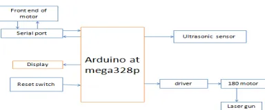
Figure1shows the block diagram of our project, the ARDUNIO AT MEGA328 processor give instructions to the ultrasonic sensor, motor LM293D IC,LCD,laser gun. The main heart of our project is ARDUNIO. Ultrasonic sensor is used to detect the objects. The ARDUNIO will receive the echo signal from the ultrasonic sensor then the ARDUINO will give the instruction to the laser gun, the laser gun starts firing with the help of motor LM293D IC. At the same time the distance of detected object will show in the LCD. The hole process will seen the front view of laptop.
B. ARDUNIO BOARD:
3 USB 7-12 v 3 v GRD 5 v
Analog Input Pins Digital Input/Output Pins Pins with ~ are PWM [Analog Output]
GRD Transmitter/Receiver Serial Connection
Microcontroller ATmega328 Operating Voltage 5V Input Voltage (recommended)7-12V Input Voltage (limits)6-20V Digital I/O Pins 14 (of which 6 provide PW M output) Analog Input Pins 6 DC Current per I/O Pin 40 mA DC Current for 3.3V Pin 50 mA
Fig 2. ARDUINO UNO board
Fig 2 the ARDUINO Uno is a microcontroller board based on the AT MEGA328. It has 14 digital input/output pins (of which 6 can be used as PWM outputs), 6 analog inputs, a 16 MHz crystal oscillator, a USB connection, a power jack, an ICSP header, and a reset button. It contains everything needed to sup-port the microcontroller; simply connect it to a computer with a USB cable or power it with a AC-to-DC adapter or battery to get started. The Uno differs from all preceding boards in that it does not use the FTDI USB-to-serial driver chip. Instead, it features the Atmega328 programmed as a USB-to-serial converter
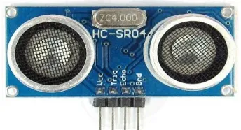
C. ULTRASONIC SENSOR:
Ultrasonic sensor actively transmit acoustic waves and receive them later. Ultrasonic transducer which transform an electrical signal into an ultrasonic wave and vice versa[1]. The ultrasonic sensor used to measure the distance of the object and to measure the amount of time taken by a pulse of sound to travel and return as echo. Ultrasound signal carries the information about the variables to be measured. The ultrasonic transmitter and receiver is a pair it uses quartz crystal 40khz transducer is used .velocity of sound in air is 330m/s. the ultrasonic sensor sends out a high frequency sound pulse and then times how long it takes for the echo of the sound to reflect back .
Sensor has 2 openings on its front:
1. Transmit ultrasonic waves (like a tiny speaker) 2. Receiver ultrasonic waves (like a tiny micro phone)
In this project we are using Ultrasonic ranging module HC - SR04 provides 2cm - 400cm .The ranging accuracy can reach to 3mm. The modules includes ultrasonic transmitters, receiver and control circuit. The ultrasonic sensor has 4 terminals
1. Echo-output signal pin 4 2 .Trigger-input signal pin2 3. Vcc-1pin
4. GND-3pin
D. MOTOR LM293D IC:
The LM293D IC it can control two dc linear motors. The linear motor can rotate up to 180 degrees
Fig 4. LM239D IC PIN DIAGRAM
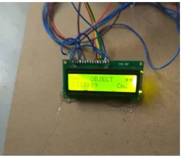
E. LIQUID CRYSTAL DISPLAY (LCD):
LIQUID CRYSTAL DISPLAY is a 2 line * 16 character display. LIQUID CRYSTAL DISPLAY will show the distance of an detected object by using ARDUINO AT MEGHA 328processor.
Fig 5. Liquid crystal display
F. LASER GUN:
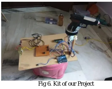
IV. HARDWARE IMPLEMENTATION
The hardware implementation of the laser gun. Here we are connected the transformer to the full wave rectifier and rectifier is connected to the 7805 regulator. The power supply is connected to the LM239D IC this IC is connected to the linear motor, this motor is interfaced with ARDUINO board. The ARDUINO board is interfaced with ultrasonic sensor and also laser gun. The ARDUINO board is also interfaced with laptop, if the enemy is detected it send the information to the ARDUINO board. Then laser gun automatically starts firing, the ARDUINO board is send the information to the LCD board that will show the distance of the object (enemy) and buzzer will also rang at the same time. The angle button is interfaced with ARDUINO .
Fig 6. Kit of our Project
V. RESULTS
These are some of the results that are detected, whenever the ultrasonic sensor transmit the signal if there is an object detected the echo signal is received back and starts firing. And buzzer also rang when object is detected.
Fig 7. Front view
The green waves indicates that the there is no object is detected. And red waves indicates that the there is an objected is detected
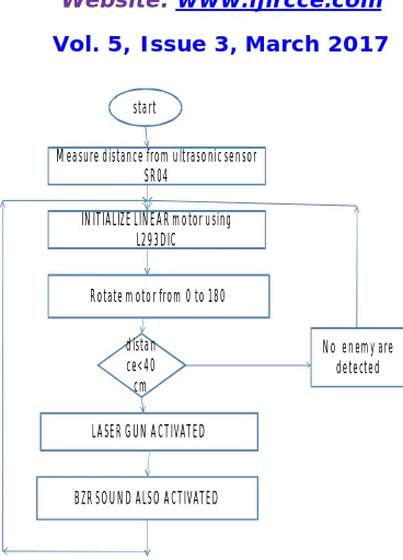
VI. SYSTEM OVERVIEW
start
Measure distance from ultrasonic sensor SR04
INITIALIZE LINEAR motor using L293DIC
Rotate motor from 0 to 180
BZR SOUND ALSO ACTIVATED LASER GUN ACTIVATED
distan ce<40 cm
No enemy are detected
Fig 8. Over all flow chart
VII. CONCLUSION
This paper enhances the security system in boarder based on ultrasonic sensor and laser gun. The LM239D IC can rotate at the angle of 180 degrees the ultrasonic sensor also rotate at that direction, if enemy is detected less than 40cm then the gun automatically starts firing and shows the graphical representation of detected enemy [object], on the laptop at the same time the distance will be displayed on the liquid crystal display (LCD) and buzzer also rang at the same time.
REFERENCES
[1] J. David and N. Cheeke, “Fundamentals of ultrasonic waves,” CRC press, Florida, USA, 2002,ISDN 08493-0130-0.
[2] S .P. Singh, A. Verma, and A.K. Shrivastava, “Design and development of robotic sewer inspection equipment controlled by embedded systems,” Proceeding of the FIRST IEEE International Conference on Emerging Trends in Engineering and Technology, Jul.2008,Nagpur, India, pp. 1317-1320.
[3] A. K. Shrivastava, A. Verma, and S.P.Singh, “Partial automation of the current sewer cleaning system,” Invertis Journal of Science and technology, Vol. 1,No. 4,2008,pp.261-265.