University of Windsor University of Windsor
Scholarship at UWindsor
Scholarship at UWindsor
Electronic Theses and Dissertations Theses, Dissertations, and Major Papers
2014
Optimal Inference Methods in Linear Models with Change-points
Optimal Inference Methods in Linear Models with Change-points
Fuqi Chen
University of Windsor
Follow this and additional works at: https://scholar.uwindsor.ca/etd
Recommended Citation Recommended Citation
Chen, Fuqi, "Optimal Inference Methods in Linear Models with Change-points" (2014). Electronic Theses and Dissertations. 5084.
https://scholar.uwindsor.ca/etd/5084
This online database contains the full-text of PhD dissertations and Masters’ theses of University of Windsor students from 1954 forward. These documents are made available for personal study and research purposes only, in accordance with the Canadian Copyright Act and the Creative Commons license—CC BY-NC-ND (Attribution, Non-Commercial, No Derivative Works). Under this license, works must always be attributed to the copyright holder (original author), cannot be used for any commercial purposes, and may not be altered. Any other use would require the permission of the copyright holder. Students may inquire about withdrawing their dissertation and/or thesis from this database. For additional inquiries, please contact the repository administrator via email
FAILURE MECHANISM OF COATED BIOMATERIALS UNDER HIGH
IMPACT-SLIDING CONTACT STRESSES
By
Ying Chen
A Dissertation
Submitted to the Faculty of Graduate Studies
through the Department of Mechanical, Automotive & Materials Engineering in Partial Fulfillment of the Requirements for
the Degree of Doctor of Philosophy at the University of Windsor
Windsor, Ontario, Canada
2014
Failure Mechanism of Coated Biomaterials under High Impact-Sliding
Contact Stresses
by
Ying Chen
APPROVED BY:
______________________________________________ X. Wu, External Examiner
Mechanical Engineering/Engineering
______________________________________________ H. Hu
Department of Mechanical, Automotive & Materials Engineering
______________________________________________ V. Stoilov
Department of Mechanical, Automotive & Materials Engineering
______________________________________________ G. Zhang
Department of Mechanical, Automotive & Materials Engineering
______________________________________________ X. Nie, Advisor
Department of Mechanical, Automotive & Materials Engineering
iii
DECLARATION OF ORIGINALITY
I. CO- AUTHORSHIP DECLARATION
I hereby declare that this dissertation does not incorporate material that is result of joint research. In all cases, the key ideas, primary contributions, experimental designs, data analysis and interpretation, were performed by the author and Dr. X. Nie as advisor.
I certify that, with the above qualification, this dissertation, and the research to which it refers, is the product of my own work.
II. DECLARATION OF PREVIOUS PUBLICATION
This dissertation includes 5 original papers that have been previously published/submitted for publication in peer reviewed journals/conference proceedings, as follows:
Thesis
Chapter Publication title
Publication status
Chapter 2
Ying Chen and Xueyuan Nie, Study on Fatigue and Wear
Behaviors of a TiN Coating using an Inclined Impact-sliding Test, Surface & Coatings Technology 206(2011)1977
Published
Chapter 3
Ying Chen, Tse Cheng and Xueyuan Nie, Wear failure
behavior of titanium-based oxide coatings on a titanium alloy under impact and sliding forces, Journal of Alloys and Compounds 578(2013) 336
Published
Chapter 4
Ying Chen and Xueyuan Nie, Study of the fatigue wear
behaviors of a WC DLC coating on 316L stainless steel, Journal of Vacuum Science and Technology A, 30 (2012) 051506
Published
Chapter 5
Ying Chen, Xueyuan Nie, Jonathan Housden, Adrian
Leyland and Allan Matthews, Substrate and bonding layer effects on performance of DLC and TiN biomedical coatings in Hank's solutions under cyclic impact-sliding loads, Surface & Coatings Technology 237(2013)219
Published
Chapter 6
Ying Chen and Xueyuan Nie, Failure mechanisms of DLC
coated Ti-6Al-4V and CoCr biomedical materials under cyclic high combined contact stresses
To be Submitted
I hereby certify that I am the sole author of this thesis and that no part of this thesis has been published or submitted for publication.
iv
extent that I have included copyrighted material that surpasses the bounds of fair dealing within the meaning of the Canada Copyright Act, I certify that I have obtained a written permission from the copyright owner(s) to include such material(s) in my thesis and have included copies of such copyright clearances to my appendix.
I declare that this is a true copy of my thesis, including any final revisions, as approved by my thesis committee and the Graduate Studies office, and that this thesis has not been submitted for a higher degree to any other University or Institution.
v ABSTRACT
This study uses a newly developed testing method— inclined cyclic
impact-sliding test to investigate the failure behaviors of different types of biomaterials,
(SS316L, Ti6Al4V and CoCr) coated by different coatings (TiN, DLC and PEO), under
extremely high dynamic contact stress conditions. This test method can simulate the
combined impact and sliding/rolling loading conditions, which is very practical in many
aspects of commercial usages. During the tests, fatigue cracking, chipping, peeling and
material transferring were observed in damaged area. This research is mainly focused on
the failure behaviors of load-bearing materials which cyclic impacting and sliding are
always involved. This purpose was accomplished in the three stages:
First, impact-sliding test was carried out on TiN coated unhardened M2. It was
found that soft substrate can cause early failure of coating due to the considerable plastic
deformation in the substrate. In this case, stronger substrate is required to support coating
better when tested under high contact stresses.
Second, PEO coated Ti-6Al-4V was tested under pure sliding and impact-sliding
wear conditions. PEO coating was found not strong enough to afford the high contact
pressure under cyclic impact-sliding wear test due to its porous surface structure.
However, the wear performance of PEO coating was enhanced due to the
sub-stoichiometric oxide. To sum up, for load-bearing biomedical implants involved in high
impacting movement, PEO coating may not be a promising surface protection.
Third, the dense, smooth PVD/CVD bio-inert coatings were reconsidered. DLC
vi
materials were tested under the cyclic impact-sliding test using a set of proper loading.
The results show that to choose a proper combination of coating, interface and substrate
based on their mechanical properties is of great importance under the test condition. Hard
substrates provide support to coating better and a ductile and adhesive interface layer can
vii DEDICATION
I would like to dedicate this dissertation to my parents for their unconditional love,
viii
ACKNOWLEDGEMENTS
This study could not have done forward without the financial support from the
Natural Sciences and Engineering Research Council of Canada (NSERC).
I would like to thank my doctoral advisor, Dr. Xueyuan Nie, for his valuable
suggestions and excellent supervision of this research work during my study.
Many thanks to my committee members (Dr. Henry Hu, Dr. Vesselin Stoilov, Dr.
Guoqing Zhang and external examiner Dr. Xin Wu) for their helpful comments and great
suggestions in the proposal and seminars.
I would like to thank Mr. Andy Jenner, Mr. Gang Li, Mr. Tse Cheng and Mr.
Junfeng Su from University of Windsor for their assistance with the experiments.
Finally, I am thankful to the faculty, staff and graduate students at the Department
ix
TABLE OF CONTENTS
DECLARATION OF ORIGINALITY ... iii
ABSTRACT ...v
DEDICATION ... vii
ACKNOWLEDGEMENTS ... viii
LIST OF TABLES ... xii
LIST OF FIGURES ... xiii
CHAPTER 1 INTRODUCTION ...1
1. GENERAL OVERVIEW ...1
1.1 What is biomaterial and its properties ...1
1.2 Typical connection of joints in the body ...5
1.3 The usage of biomaterials ...5
1.4 Challenges for using artificial bio-implants ...6
1.5. Stress analysis of hip and knee implants ...6
2. TESTING METALLIC BIOMATERIALS IN THIS DISSERTATION ...9
3. COATING & SURFACE TREATMENT OF THE BIOMATERIALS ...20
4. REVIEW OF IN VITRO TEST OF BIOMATERIALS ...26
5. IMPACT TESTS FOR COATED & UNCOATED BIOMATERIALS ...31
6. OBJECTIVES OF THIS RESEARCH ...40
7. THE LAYOUT OF THE DISSERTATION ...41
REFERENCES ...43
CHAPTER 2 STUDY ON FATIGUE AND WEAR BEHAVIORS OF A TIN COATING USING AN INCLINED IMPACT-SLIDING TEST ...48
1. INTRODUCTION ...48
2. EXPERIMENTAL DETAILS ...49
2.1 TiN coating characterizations. ...49
2.2 Impact-sliding wear test machine ...50
2.3 The experiment parameters ...52
3. RESULTS AND ANALYSIS ...53
3.1 Crack observation ...53
3.2 The evolution of fatigue failures in the impact tests ...57
4. CONCLUSIONS AND DISCUSSION ...60
REFERENCES ...61
CHAPTER 3 WEAR FAILURE BEHAVIOR OF TITANIUM-BASED OXIDE COATINGS ON A TITANIUM ALLOY UNDER IMPACT AND SLIDING FORCES 63 1. INTRODUCTION ...63
2. EXPERIMENTAL DETAILS ...65
2.1 Sample coupon ...65
x
3. RESULTS AND DISCUSSION...69
3.1 Characteristics of PEO coatings on Ti-6Al-V ...69
3.2 Wear behaviors of as-made and polished coatings and uncoated substrate. .70 3.3 OM and SEM observations on POD wear tracks ...73
3.4 OM and SEM observations on impact tracks ...76
4. CONCLUSIONS ...83
REFERENCES ...85
CHAPTER 4 STUDY OF THE FATIGUE WEAR BEHAVIORS OF A WC DLC COATING ON 316L STAINLESS STEEL ...89
1. INTRODUCTION ...89
2. EXPERIMENTAL DETAILS ...91
2.1. The specimen ...91
2.2. Pin-on-disc wear test on the DLC coating ...91
2.3. The sliding test and force curve of each test cycle ...92
3. RESULTS AND DISCUSSION...94
3.1. Nano-indentation test on the DLC coating ...94
3.2. SEM observations on the pin-on-disc wear tracks ...95
3.3. SEM observations on impact-sliding tracks ...99
4. CONCLUSIONS ...112
REFERENCES ...115
CHAPTER 5 SUBSTRTE AND BONDING LAYER EFFECTS ON PERFORMANCE OF DLC AND TIN BIOMEDICAL COATINGS IN HANK’S SOLUTIONS UNDER CYCLIC IMPACT-SLIDING LOADS ...117
1. INTRODUCTION ...117
2. EXPERIMENTAL DETAILS ...119
2.1 Sample preparations and hardness measurement: ...119
2.2 Testing methods ...121
3. RESULTS AND ANALYSIS ...125
3.1Impact-sliding tests on coated Ti-6A-4V ...125
3.2 Impact-sliding tests on coated M2 substrate ...129
3.3 Effect of the bonding layers ...133
4. CONCLUSIONS ...142
REFERENCES ...143
CHAPTER 6 FAILURE MECHANISM OF DLC COATED Ti-6Al-4V AND COCR BIOMATERIALS UNDER CYCLID HIGH COMBINED CONTACT STRESSES ....146
1. INTRODCUTION ...146
2. EXPERIMENTAL DETAILS ...147
2.1 Test samples ...147
2.2 Potentiodynamic polarization test ...149
2.3 Pin-on-disc test ...149
xi
2.5 Cyclic impact-sliding wear test ...150
3. OBSERVATIONS AND ANALYSIS ...152
3.1 Pin-on-disc (POD) test on bare and DLC coated CoCr and Ti6Al4V ...152
3.2 Inclined cyclic impact-sliding wear test results ...159
4. CONCLUSION ...164
REFERENCES ...165
CHAPTER 7 SUMMARY ...167
1. CRITICAL PARAMETERS TO THE FAILURE OF THE COATINGS ...168
1.1 Substrate effects (Chap. 2, 4, 5, 6). ...168
1.2 Bonding layer effects (Chap. 2, 4, 5). ...168
1.3 Coating wear-resistance effects (Chap. 4-6). ...169
1.4 Coating surface morphology & roughness (Ra & Rsk) effects (Chap. 3). ..169
1.5 Coating thickness effects (Chap. 3). ...169
2. SUMMARY OF THE TESTING RESULTS ...170
CHAPTER 8 GENERAL CONCLUSIONS AND FUTURE WORK ...174
1. CONCLUSIONS OF EACH CHAPTER ...174
CHAPTER 9 STATEMENT OF ORIGINALITY ...183
APPENDICES ...184
Appendix A ...184
REFEREED JOURNAL PUBLICATIONS ...194
xii
LIST OF TABLES
Table 1- 1 Implants division and type of metals used [10] ... 3
Table 1- 2 Mechanical properties of bone and metal biomaterials [6, 7, 10] ... 9
Table 1- 3 Chemical compositions of ASTM F-75 CoCr alloy, Ti6Al4V and 316L [6] ... 9
Table 1- 4 Elastic modulus and hardness of TiN and DLC coatings manufactured by Tecvac. Ltd [49]. ... 24
Table 3- 1 Chemical composition of Ti-6Al-4V in weight percent. ... 66
Table 3- 2 Parameters of PEO procedure and thickness and roughness of coatings ... 66
Table 3- 3 Atomic ratio of oxygen vs. cations in the polished coatings and wear tracks. 76
Table 3- 4 Estimated contact pressures during the impact and pressing according to Herztian’s theory. ... 77
Table 3- 5 Evaluation on failure levels of the PEO under different loading conditions. ... 78
Table 4- 1 Evaluation of the degree of failure of the WC DLC coating vs. number of test cycles. ... 101
Table 5- 1 Properties of TiN and DLC coatings ... 120
Table 5- 2 Results of electrochemical corrosion tests in a HBSS solution at 37 ºC. ... 137
Table6- 1 Chemical compositions of ASTM F-75 CoCr alloy and Ti-6Al-4V [11-13] . 148
Table6- 2 Hertz contact stresses of the testing couples in POD and impact-sliding tests. ... 150
Table6- 3 Testing cycles of both coated and uncoated CoCr and Ti-6Al-4V in the impact-sliding wear test. ... 151
Table6- 4 The COF measured in dry and wet tests for coated and uncoated samples ... 158
Table6- 5 Wear rate in dry and wet tests for coated and uncoated samples ... 158
Table6- 6 Hardness and elastic modulus on damaged CoCr and Ti6Al4V substrates .... 161
Table 7- 1 Summary of tested tracks on DLC and TiN coatings ... 172
xiii
LIST OF FIGURES
Figure 1- 1 Metallic devices and metallic biomaterials’ applications [11]. ... 4
Figure 1- 2 Schematic representation of the load transfer before and after total hip arthroplasty (THA) [15, 16]. ... 7
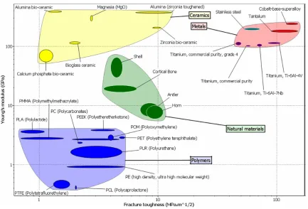
Figure 1- 3 Mechanical properties of natural materials in comparison with bulk materials for medical purpose. [17]. ... 8
Figure 1- 4 Reconstruction of surface oxide (inert) layer in the biological environment .. 15
Figure 1- 5 Classification of processes used for coating at the industrial level [44] ... 21
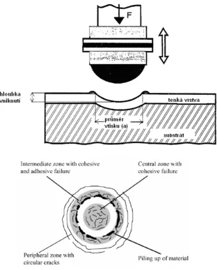
Figure 1- 6 Schematic illustration of the various types of surface and subsurface damage arising from a spherical indenter [59]. ... 28
Figure 1- 7 Hip and knee implant wear simulators. ... 30
Figure 1- 8 Ball-on-plate repetitive impact testing ... 33
Figure 1- 9(a) A dual cylinder-on-plane instrument by . Ramalho [77] and (b) An inclined impact test by Bouzakis [76]. ... 35
Figure 1- 10 (a) Schematic illustration of cyclic inclined impact-sliding wear tester, (b) normal and tangential forces applied by impact ball to the inclined coating surface, and (c) schematic illustration of the tested track from cross-sectional way. ... 37
Figure 1- 11 Dynamic loading variations during one test cycle with Fi=200N and Fpmax=400N. ... 38
Figure 1- 12 Classification of failure based on percentage of exposure area of the substrate. ... 39
Figure 2- 1 Schematic of Impact-Sliding Wear Test Fixture. 1 - Ball indenter drive (e.g., air cylinder), 2 - ball indenter, 3 - flat specimen (i.e., coating), 4 - rigid frame, 5 - rotatable rocker, 6 - return drive (e.g., spring). ... 51
Figure 2- 2 The force curve in one impact cycle under Fi/Fp=520 N/400 N. ... 53
xiv
Figure 2- 4 The radial cracks on head part of each impact scars. (a) 250 cycle sample, (b) 500 cycle sample and (c) 750 cycle sample. ... 55
Figure 2- 5 Cohesive cracks at the center of the contact zone. (a) 250 cycle sample, (b) 500 cycle sample and (c) 750 cycle sample. ... 58
Figure 2- 6 Peripheral crack which parallel to each other distributed on both edges of the tail part. (a) 250 cycle sample, (b) 500 cycle sample and (c) 750 cycle sample. ... 59
Figure 3- 1 Schematic of surface (cross-sectional) with a negative skewness Rsk [33,
34]. ... 67
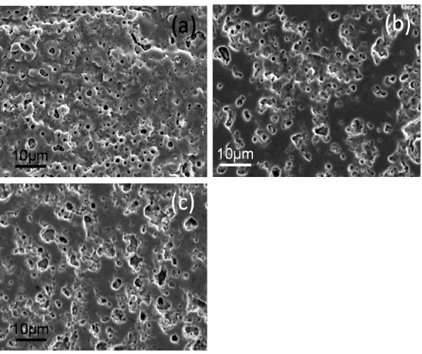
Figure 3-2 SEM micrographs of surface morphologies of polished sample surfaces (a) S1 (b) S2 and (c) S3. ... 70
Figure 3- 3 COF vs. sliding distance in POD wear tests for coatings 1-3 and Ti-6Al-4V substrate. (a) Before polishing, 2N, 100m; (b) After polishing, 2N, 300m. ... 71
Figure 3- 4 OM and SEM micrographs on POD wear tracks under 2N, 300m condition (after polishing work): (a, b) S1, (c, d) S2 and (e, f) S3. EDX spectra taken from some typical areas in the SEM micrographs are shown in Fig. 3-5. ... 74
Figure 3- 5 EDX spectra collected on related areas in Fig. 3-4 and atomic percentage of main elements in the center of wear tracks. ... 75
Figure 3- 6 Schematic illustration of coating failure behavior in the inclined impact- sliding tests. Area I, porous top layer; area II, dense inner layer; area III, diffusion layer. ... 77
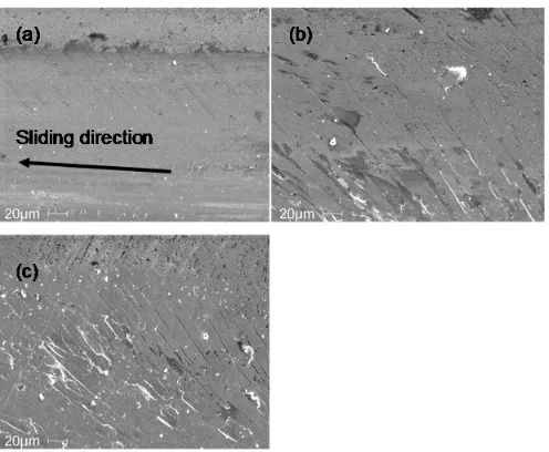
Figure 3- 7 Optical micrographs on impact-sliding tracks under (a1-c1) Fi =200 N, Fpmax =400 N and (a2-c2) Fi =80 N, Fpmax =200 N. The head crater is in the left for all OM and SEM micrographs. ... 78
Figure 3- 8 OM and SEM micrographs on 100 cycles’ impact tracks under 140 N/300 N loading condition, in which (a-c) are OM images, (d-f) are SEM images. The damages on pin balls were inserted in the OM micrographs. EDX spectra on the typical areas are shown in Fig. 3-8. All the images are at a same magnification, the scale bar is shown in (e). ... 80
Figure 3- 9 EDX spectra taken on related areas which shown in Fig. 3-8. ... 81
xv
Figure 4- 2 Load—displacement curve of the DLC coating by nano indentation test. ... 95
Figure 4- 3 Backscatter SEM observations of the pin-on-disc wear tracks on the DLC coating after (a) 5,000, (b) 30,000, (c) 60,000 and (d) 275,000 revolutions; (e) EDX spectrum taken inside the wear track (area A). The sliding direction was from right to left. ... 97
Figure 4- 4 Dynamic COF curves of the DLC coating after 275,000 revolutions of the pin-on-disc wear test. ... 98
Figure 4- 5 Back scatter SEM observation of entire impact tracks on the DLC coating under a Fi/Fp=200 N/400 N impact-sliding force after (a) 10, (b) 500, (c) 1000 and (d) 1500 impact cycles. ... 100
Figure 4- 6 The trend of changes of the failure area as a function of the impact-sliding test cycles. Total failure = the sum of failures at the head, in the middle and near the tail of the sliding track. ... 102
Figure 4- 7 Evolution of fatigue cracks in the (A) head edge, (B) head/tail interface area, (C) tail center, and (D) tail edge. Columns (1-4) show the test cycles numbering 10, 500, 1000 and 1500, respectively. ... 103
Figure 4- 8(a-e) 45º tilted SEM observations on the cut sample tested at Fi/Fp=200 N/400 N after 1000 cycles, and (f-h) EDX spectra taken on areas I, II and III, respectively. ... 105
Figure 4- 9(a) SEM and (b) 45ºtilted optical micrographs on impacted stainless steel, (c) sliding grooves and wear debris in the impact-sliding track and a (d) optical photo of the counterface steel ball. ... 108
Figure 5- 1. (a) load curve in one impact–sliding wear test cycle showing dynamic impact force Fi and increasing pressing force Fp. (b) Setup illustration of inclined impact–sliding tester with a tested track, in which, 1—ball specimen drive (e.g., air cylinder), 2—ball specimen, 3—flat specimen (i.e., coating), 4—rigid frame, 5— rotatable rocker, and 6—return drive (e.g., spring). ... 121
Figure 5- 2 Schematic illustration of typical failure modes (chipping, peeling and material transfer) on damaged coating. ... 123
xvi
Figure 5- 4 Optical and SEM micrographs of (a) 5000 cycles' tested track of TiN coating and (b) 2000 cycles' tested track of DLC coating on Ti–6Al–4V alloy under Fi = 140 N, Fp = 300 N, in a HBSS lubricated condition. ... 127
Figure 5- 5 COF vs. sliding revolutions of pin-on-disc tests on DLC and TiN coatings under dry and HBSS lubricated conditions. ... 128
Figure 5- 6 Optical and SEM micrographs on (a) TiN coating and (b)DLC coating onM2 substrate under Fi = 140 N, Fpmax = 300 N,1000 cycle test in a dry condition. Inserts i and ii are the framed areas at high magnifications. ... 130
Figure 5- 7 Optical micrographs of (a) 5000 cycles' tested track of TiN coating and (b)1000 cycles' tested track of DLC coating onM2 under Fi = 140 N, Fp = 300 N, in a HBSS lubricated condition. (c, d) EDX spectra on point A of (a) and point B of (b), respectively. ... 131
Figure 5- 8 Optical micrographs of DLC coated M2 tested with the increasing cycles of (a) 500, (b) 600, (c) 650 and (d) 800 cycles. ... 134
Figure 5- 9(a, b) Potentiodynamic polarization curves of DLC coated Ti–6Al–4V andM2 (coated and uncoated) tested in a HBSS solution at 37 °C; (c, d) schematical illustration of partially failed DLC from cross-sectional way. . 136
Figure 5- 10 SEM observations on corroded tracks after being tested under (a) 600 cycles on DLC coatedM2 and (b) 4000 cycles on TiN coatedM2. (c, d) EDX spectra on point A of (a) and point B of (b), respectively. ... 140
Figure 5- 11(a, b) Potentiodynamic polarization curves of TiN coated Ti–6Al–4V (damaged and undamaged) and tested in a HBSS solution at 37 °C; (c, d) schematical illustration of partially failed DLC from cross-sectional way. (e, f) SEM observations on tested tracks on TiN coated (e) Ti–6Al–4V and (f) M2. 141
Figure 6- 1 Pin-on-disc test results of uncoated CoCr and Ti-6Al-4V alloys, where (a and a’), COF vs. sliding revolutions; (b-d) Optical observations on sliding tracks; (b’-d’) Cross-width surface profile on the wear tracks in b-e; and (A-D) SEM observations inside sliding tracks of the insert area A-D B insert in d-e... 154
Figure 6- 2 Results of corrosion tests of CoCr and Ti6Al4V bulk materials in HBSS environment. ... 156
xvii
Figure 6- 4 Optical observations and cross-width measurement on tested tracks of CoCr substrate in dry and wet test conditions, where (a) 100 cycles dry test and (b) 5000 cycles wet test; (A and B)SEM microscopy on area A and B insert in a. ... 160
Figure 6- 5 Optical observations on tested tracks of Ti6Al4V substrate in dry and wet test conditions. (a) 3 cycles dry tests, (b) 100 cycles dry test and (c) 100 cycles wet test . ... 161
Figure 6- 6 Optical observations on tested tracks of CoCr and Ti6Al4V substrate in dry condition . ... 162
Figure 6- 7 Optical observations and cross-width surface profile measurement on tested tracks of CoCr and Ti6Al4V substrate in wet condition . ... 163
1
CHAPTER 1 INTRODUCTION
1. GENERAL OVERVIEW
1.1 What is biomaterial and its properties
A biomaterial is any synthetic material that is used to replace or restore function
to a body tissue and is continuously or intermittently in contact with body fluids [1-3].
Exposure to body fluids places several strict restrictions on materials that can be used as
biomaterial [1-3]. First and foremost, a biomaterial must be biocompatible—it should not
elicit an adverse response from the body, and vice versa. Additionally, it should be
nontoxic and noncarcinogenic. These requirements eliminate many engineering materials
that are cost-effectively available. Next, the biomaterial should possess adequate physical
and mechanical properties to serve as augmentation or replacement of body tissues.
The most common classes of materials used as biomedical materials are polymers,
metals, and ceramics [4, 5]. These three classes are used singly and in combination to
form most of the implantation devices available today.
The ideal material or material combination should exhibit the following properties
[5-10]:
A biocompatible chemical composition to avoid adverse tissue reactions.
Excellent resistance to degradation (e.g., corrosion resistance for metals).
Acceptable strength to sustain cyclic loading endured by joint.
A low modulus to minimize bone resorption.
High wear resistance to minimize wear debris generation.
Metals have been used as implants since more than 100 years ago when Lane first
2
metal implants faced corrosion and insufficient strength problems. Shortly after the
introduction of the 18-8 stainless steel in 1920s, which has had far-superior corrosion
resistance to other metals available in that time, it immediately attracted the interest of
the clinicians. Thereafter, metal implants experienced vast development and clinical use.
The high strength and resistance to fracture that this class of material can provide
assuming proper processing, gives reliable long-term implant performance in major
load-bearing situations. Coupled with a relative ease of fabrication of both simple and complex
shapes using well-established and widely available fabrication techniques (e.g., casting,
forging, machining), this has promoted metal use in the field of orthopedics and dentistry
primarily, the two fields in which highly loaded devices are most common.
The advantage of metal is their strength and therefore their resistance to damage in
comparison with ceramic and polymer materials. The ceramics is poor in toughness,
particularly with regards to its notch toughness; therefore, ceramics often result in a
sudden fracture. Consequently, they are unsuitable for use in regions that are subject to
heavy loads and repeated impact loads, or as parts (for example, screws) where pressure
is concentrated. The weakness of polymeric materials makes the polymers inapplicable
in locations where a large load is applied, and their inability to withstand heat limits
sterilization methods.
Up to now, the three most used metals for implants are stainless steel, CoCr alloys
and Ti alloys [5-8]. The first stainless steel used for implants contains ~18wt% Cr and
~8wt% Ni, and it is more resistant to corrosion than a carbon steel. Further addition of
molybdenum Mo) has improved its corrosion resistance further, known as type 316
3
wt.% which improved its corrosion resistance to chloride solution, and named as 316L.
Table 1-1 summarized the type of metals generally used for different implants division.
Some of the metal implants are illustrated in Fig. 1-1.
Table 1- 1 Implants division and type of metals used [10]
Division Example of implants Type of metal
Cardiovascular
Stent 316L SS; CoCrMo; Ti
Artificial valve Ti6Al4V
Orthopedic
Bone fixation (plate, screw,
pin) 316L SS; Ti; Ti6Al4V
Artificial joints CoCrMo; Ti6Al4V; Ti6Al7Nb
Dentistry Orthodontic wire 316L SS; CoCrMo; TiNi; TiMo
Filling AgSn(Cu) amalgam, Au
Craniofacial Plate and screw 316L SS; CoCrMo; Ti; Ti6Al4V
Otorhinology Artificial eardrum 316L SS
As shown in Fig. 1-1, a typical hip prosthesis consists of the femoral stem, a
femoral ball, and a polymeric (ultrahigh molecular weight polyethylene, or UHMWPE)
socket (cup) with or without a metallic backing [1-3]. Femoral components usually are
manufactured from Co-Cr based alloys or titanium alloys. The ball (articulating portion
of the femoral component) is made either of highly polished Co-Cr alloys or of a ceramic.
4
5 1.2 Typical connection of joints in the body
The articulations are divided into three classes: synarthroses or immovable,
amhiarthroses or slightly movable, and diarthroses or freely movable joints [12].
Synarthroses (immovable articulations) include all those articulations in which
the surfaces of the bones are in almost direct contact, fastened together by intervening
connective tissue or hyaline cartilage, and in which there is no appreciable motion, as in
the joints between the bones of the skull, dental implants and stem-femur connection in
the total hip replacements (THPs).
Amphiarthroses (slightly movable articulations) locate between the contiguous
bony surfaces which are either connected by broad flattened discs of fibrocartilage or are
united by an interosseous ligament.
Diarthroses (freely movable articulations) include the greater number of the joints
in the body. In such a joint, the contiguous bony surfaces are covered with articular
cartilage and enclosed by a synovial cavity with synovial fluid. This kind of body fluid is
a viscous, which contains proteinases and lubricin, some salt and other ingredients. The
principal role of synovial fluid is to reduce friction between the articular cartilage of
synovial joints during movement [13].
1.3 The usage of biomaterials
One of the primary reasons that biomaterials are used is to physically replace hard
or soft tissues that have become damaged or destroyed through some pathological process
[1-7, 9]. Although the tissues and structures of the body perform for an extended period
of time in most people, they do suffer from a variety of destructive processes, including
6
such circumstances, it may be possible to remove the diseased tissue and replace it with a
more suitable synthetic material.
Almost all interactions between cells/tissues and a metal implant occur at the
implant surface – As such, the surface properties of metals implant materials are of great
importance.
1.4 Challenges for using artificial bio-implants
Loosening is one of the most common complications resulting from a faulty
device. This occurs when components of an implant begin to separate from the bone.
Four principal causes of implantation loosening are [14]:
Mechanical failure of the implant or cement;
Introduction of wear debris into the interface region;
Relative motion across the interface;
Stress shielding in the bone.
Each of these phenomena can initiate a biological response in the bone leading to
resorption and the eventual loosening of the implant.
1.5. Stress analysis of hip and knee implants
Fig. 1-2 shows schematic representation of the load transfer in the proximal femur
before and after hip replacement [15, 16]. In the natural state, the stress is distributed over
the entire cross section of the femur. Bending and axial compression are the major modes
of loading. The post-surgery stress state is significantly different mainly due to the
manner in which the load is transferred to the femur. In this case, the load is partially
transferred through shear across the bone/cement/prostheses interfaces. This altered load
7
the prosthesis. The interface shear stresses are further increased due to the stiffness ratio
between the prosthesis and the bone, typically of the order of 10 : 1 and higher.
Figure 1- 2 Schematic representation of the load transfer before and after total hip
arthroplasty (THA) [15, 16].
In addition, the bending displacements in the bone surrounding the stem are
reduced because of the relatively high flexural stiffness of the prosthesis. This reduced
bending unloads the outer fibers of femur leading to a state of stress shielding. The
change in the load distribution increases stresses in some regions and reduces them in
others. If these changes are large enough, they can lead to adaptive bone remodeling.
Areas that see higher loads, may experience an increase in bone mass, while areas that
see a reduction in load may experience a decrease. The other factors mentioned earlier
might also play a role in this remodeling but stress shielding is often implicated.
The natural stress distribution in the femur is significantly altered after total hip
8
causing a reduction of stress in some regions of the remaining bone. This phenomenon is
commonly known as stress shielding. In response to the changed mechanical
environment the shielded bone will remodel according to Wolff's law, resulting in a loss
of bone mass through the biological process called resorption. Resorption can, in turn,
cause or contribute to loosening of the prosthesis. The problem is particularly common
among younger THA recipients.
Most synthetic biomaterials used for implants are commonly-used materials that
are familiar to an average materials engineer or scientist [17]. Fig. 1-3 highlights the
extraordinary mechanical properties of bone in contrast to technical bulk materials used
for medical purpose.
Figure 1- 3 Mechanical properties of natural materials in comparison with bulk
9
In some situations, such as in total hip and knee replacement, the high strength of
the metal in the implant induces it to assume more than its share of responsibility for the
load in that region. This decreases the load born by the surrounding tissue and therefore
shields it from experiencing stress. The mechanical properties of bone and three metal
biomaterials are summarized in Table 1-2. However, those are just general data of the
materials, the value of which may vary largely due to the fabrication processes. For
example, the UTS for as-case CoCrMo alloy is around 725 MPa, but the hot forged one
has a value of 1205 MPa.
Table 1- 2 Mechanical properties of bone and metal biomaterials [6, 7, 10]
Materials Young’s Modulus
(GPa) Yield Stress (MPa) Tensile Strength (MPa) Cortical
bone 15-30 30-70 70-150
Co-Cr 210-250 448-1606 793
Ti-6Al-4V 110 485 760-860
316L SS 190 220-1213 586-1351
2. TESTING METALLIC BIOMATERIALS IN THIS DISSERTATION
Three types of metallic biomaterials were used as substrates in this study, the
detailed composition of each material were summarized in Table 1-3 as follows.
Table 1- 3 Chemical compositions of ASTM F-75 CoCr alloy, Ti6Al4V and 316L [6]
ASTM F-75 Composition
(wt.%)
Ti-6Al-4V
Compositi on (wt.%)
AISI 316L Compositi on (wt.%) Chromium (Cr) 27.0% to 30.0% Carbon
(C)
0.1% max Carbon (C) 0.03% max
Molybdenum (Mo)
5.0% to 7.0% Iron (Fe) 0.3% max Silicon (Si)
1% max
Nickel (Ni) 0.50% max Nitrogen
(N)
0.05% max Manganese (Mn)
2% max
Iron (Fe) 0.75% max Oxygen
(O) 0.2% max Phosphorous (P) 0.045% max Carbon (C) 0.20% to 0.35% Aluminiu
10
Silicon (Si) 1.00% max Vanadiu
m (V) 3.5-4.5% Chromium (Cr) 18% max Manganese (Mn)
1.00% max Hydroge
n (H) 0.015% max Nickel (Ni) 14% max
Tungsten (W) 0.20% max Titanium
(Ti) Balance Molybdenum (Mo) 3% max Phosphorous
(P) 0.020% max Nitrogen (N) 0.1% max
Sulphur (S) 0.010% max Iron (Fe) Balance
Nitrogen (N) 0.125% to 0.250% Aluminium
(Al)
0.10% max
Titanium (Ti) 0.10% max
Cobalt (Co) Balance
I. Stainless steel
The first metal alloy developed specifically for human use was the
“Vanadium steel” which was used to manufacture bone fracture plates and screws [5-7].
It is no longer used in implant application, because its corrosion resistance in vivo is
inadequate. The 316L stainless steel materials are resistant to a wide range of corrosive
agents due to their high Cr content (more than 12 wt.%), which allows the formation of a
strongly adherent, self-healing and corrosion resistant coating oxide of Cr2O3. Several
types of stainless steel are available and the most widely used for implant manufacture is
austenitic stainless steel. In order to be austenitic at room temperature, stainless steel
needs to contain a certain amount of austenite stabilizing elements such as Ni or Mn. The
stainless steel most widely used in clinical applications is AISI 316L that contains
0.03 wt.% C, 17–20 wt.% Cr, 12–14 wt.% Ni, 2–3 wt.% Mo and minor amounts of
nitrogen, manganese, phosphorus, silicon and sulphur.
Stainless steel is widely used in temporary devices such as fracture plates, screws
11
processing [5, 6, 17]. Their use in orthopedic joint prosthesis is restricted because other
metallic alloys such as Ti-based and Co–Cr-based alloys exhibit superior mechanical and
corrosion properties.
The wear resistance of austenitic stainless steel is rather poor and this is the
reason why the metal-on-metal pairs in joints such as the hip (femoral head and
acetabular cup) were discarded, because of high friction and the large number of wear
debris particles that were produced, which led to a rapid loosening. This is one of the
main reasons why the Co–Cr–Mo alloy (ASTM F75) was introduced in hip prostheses.
Co–Cr-based alloys exhibit an excellent corrosion resistance, even in chloride
environments, that they combine with a good wear resistance [19]. Their mechanical
properties are also superior, most significantly their fatigue strength. These materials
have a high elastic modulus (220–230 GPa) similar to that of stainless steel (approx.
200 GPa), and an order of magnitude higher than that of cortical bone (20–30 GPa). On
contact with bone, the metallic devices will take most of the load due to their high
modulus, producing stress shielding in the adjacent bone. The lack of mechanical stimuli
on the bone may induce its resorption that will lead to the eventual failure and loosening
of the implant [20-22]. It is necessary to make a good design of the geometric shape of
the implants to minimize the disadvantage of stress-shielding.
II. Titanium and its alloys
The use of titanium as implant material goes back to 1930s. it is primarily due to its
lightness and good mechano-chemical properties [6, 18]. Titanium is featured by its light
weight. Its density is only 4.5g/cm3 compared to 7.9g/cm3 for 316 stainless steel and
12
their excellent tensile strength and pitting corrosion resistance which make it most widely
used for implant applications [6]. Titanium alloyed with Ni, i.e. Nitinol, forms alloys
having shape memory effect which makes them suitable in various applications such as
dental restoration wiring.
Young’s modulus of Ti and Ti alloys is valued as it is half that of stainless steel or
Co-Cr alloy, and is relatively close to that of cortical bones and therefore create less risk
of stress protection of bone. The excellence of Ti in mechanical biocompatibility has led
to its widespread use in the area of biomaterial such as in fixtures of dental implants,
fracture fixation materials and artificial joints. In addition, from past experience, it has
become clear that its compatibility with both hard and soft tissues surpasses that of all
other metal materials [23]. Its compatibility with blood is not yet clear, however, its
safety for application within the human body has been well established, and it lacks
toxicity. Its safety and tissue compatibility are a result of the chemical characteristic of
Ti, or more specifically, its surface properties, and knowledge of these properties is thus
of extreme importance.
Ti is an extremely active element, and its standard electrode potential for the
reaction, Ti → Ti + 2 e- with regards to the standard hydrogen electrode is as low as
-1.63V, indicating its high activity. According to Pourbaix [24], of the metal elements that
are in practical use, Ti is the most thermodynamically active (easily-ionized) metallic
element. This active property forms a basis for the chemical characteristics of Ti, such as
the difficulty encountered in working the metal, its resistance to corrosion, and its low
thermal conductivity. Although Ti as an element is extremely active, Ti as a metallic
13
Ti. It reacts readily with water molecules in solution, or moisture in the atmosphere to
form a thin layer (≈5 nm thick) of titanium oxide on the metal surface. Even when the
surface is scratched, the newly exposed sub-layer rapidly becomes coated with oxide,
appearing inert. For this reason, its resistance to corrosion is much higher than that of
stainless steel or Co-Cr alloy. This nature not only provides resistance to corrosion, but
also explains its ready incorporation into the body, and its lack of toxicity [25].
Many Ti alloys have been developed for biomedical purposes [26-28]. Ti-6AI-4V
alloy, a typical Ti alloy is an α+β-type, and used commonly in biological materials. This
alloy has several properties that are superior to those of other Ti alloys, including
processability, thermal processability, and weldability, in addition to its resistance to
corrosion, strength, and biocompatibility. A notable characteristic of Ti-6AI-4V alloy is
its 0.2% proof stress of 895 MPa, a value that is much higher than even that of stainless
steel or Co-Cr-Mo alloys. This indicates that even under a high load, it is not easily
plastically deformed. However, titanium alloys are insufficient in tribological
performances [29, 30], characterized by high coefficient of friction, severe adhesive wear
with high tendency to seizing and low abrasion resistance. There are two widely accepted
reasons for the inferior tribological properties: the first is its low resistance to plastic
shearing and the low work hardening; and the second reason is due to the low protection
exerted by the surface oxide. The oxide is formed by high flash temperatures caused by
friction during sliding. The stationary or dynamic contact loads between Ti-alloy
components and other metals or itself can cause damage to the thin oxide film and thus
lose the protection.
14
Biomaterials function by interacting with biological tissues; therefore the reaction
between the material surface and biological tissues needs to be fully understood [31]. It is
self-evident that reactions are determined by the properties of the material surface,
including resistance to corrosion and tissue biocompatibility. The metal surface under
atmospheric conditions or in solutions always forms a layer of reactive film. The film that
is formed in solution displays low solubility, and provided it has been formed without
pores and is highly adhesive, it becomes resistant to corrosion (an inert/passive film). The
passive film that is formed is transparent and is as thin as 1-5 nm. Metals such as Ti, Zr
and Ta, that are essential as metal biomaterials, are easily oxidized (these are also known
as valve metals). As this layer envelops the metal surface, it stops the progress of
corrosion passed this point, therefore resulting in an apparently inert metal [32]. With
regards to Ti, the reaction below occurs in solution at room temperature, resulting in its
inert properties.
Ti + 2H2O → TiO2 + 4H+ + 4e- (anode reaction) (1)
2H+ + 2e- → H2 (cathode reaction, in acidic solution) (2)
O2 + H2O + 4e- → 4OH- (cathode reaction, in neutral or alkaline solution) (3)
The reaction described by equation (1) does not occur in one step, but in steps from
Ti ,Ti2+, Ti3+ to Ti4+.
The same reaction (1) can occur with atmospheric moisture; Ti as a biomaterial
generally exists as an inert metal covered by an oxidative layer.
The passive film of Ti is made up of amorphous or low crystalline stoichiometric
TiO2. However, this is not completely amorphous, and includes lower oxide and
15
Any damage to the surface can be self-repaired rapidly. As shown in Fig. 1-4 when
the passive film is damaged, outflow of Ti ions and the anodic current that accompany
regeneration of the film can be detected, however, the current declines within a short
period, once the film has regenerated. This is why the corrosion resistance of these
materials is high.
Even though an inert film is formed on the titanium surface, the surface remains
active. It reacts with the moisture in air, forming hydroxyl groups on the surface. Due to
the passive surface layer of Ti as shown in Fig. 1-4, an inert film is formed in solution as
well as on reaction with moisture in the atmosphere, resulting in the formation of
hydroxyl groups.
Figure 1- 4 Reconstruction of surface oxide (inert) layer in the biological environment
b. Reconstruction of the oxide passivation film
The passive film appears to be in a stable state, however, a cycle of repetitive partial
solubilization and re-deposition can be detected at the microscopic level. The structure is
16
[33,34]. Calcium phosphate is also formed on the surface of Ti-6Al-4V alloy when it is
used for fracture fixation. In particular, calcium phosphate with a large [Ca/P] ratio can
be detected on the surface of an intramedullary needle inserted into the medullary cavity.
Furthermore, when Ti or Ti alloy is immersed in Hank’s solution, calcium phosphate has
been found to be deposited, and under conditions used for cell culture, formation of
sulfite or sulfide has also been found. These findings show that the physiological
processes that occur in the body are well reflected by in vitro experiments.
c. Corrosion-resistant properties of titanium
Metal Ti itself does not exhibit toxicity, but this can arise from the metal ions or
derivatives of the metal including oxides, hydroxides, salts, or complexes that result as a
product of rust or corrosion. These can subsequently bind biological molecules or cellular
organelles, inhibiting their biological functions. The passive state maintaining current
density is lower for Ti and Ti-6Al-4V than for other materials, suggesting relatively high
resistance to corrosion.
Ti-6Al-4V, reported by [31], showed charge stabilization after five days of being
immersed in biological saline, but in Hank’s solution, the charge continued to show a
gradual increase. This suggests that the passive film of Ti is stable in saline, but the film
grows in Hank’s solution. As noted above, the reason for this is formation of a calcium
phosphate film on the Ti surface in Hank’s solution.
On investigation of the effect of uric acid and amino acids, immersion charges
measured for a period of 150 days did not change, suggesting that these biological
molecules had no effect on the corrosion of Ti alloys. Proteins are generally known to
17 effect on Ti or Ti alloys.
III. Cobalt-Chrome alloys
CoCr alloys have been utilized for many decades in making artificial joints [35].
They are generally known for their excellent wear resistance. Especially the wrought
CoNiCrMo alloy has been used for making heavily loaded joints such as ankle implants.
Amongst all the above discussed alloys, the CoCrMo is most corrosion resistant.
However, it is not preferred for bearing surfaces of implants as bare material due to its
poor frictional properties (debris and ion-release). The superior mechanical properties
(particularly fatigue strength) make it useful for implants which require long service life.
The chloride content of the environment is an important factor to consider when
looking at the corrosion of an alloy. Chloride ions are aggressive species which can lead
to localized corrosion processes in the form of pitting and crevice corrosion. If the
chloride ions are present in an aerated solution, this is believed to increase the corrosion
rate of CoCrMo, Ti6Al4V and 316L stainless steel in aqueous environment. When tested
under a HBSS solution, the corrosion resistance (Rc) measured by potentiodynamic
polarization test in our lab showed that CoCrMo had greatest resistance, Ti6Al4V
showed moderate resistance while 316L, although it show good corrosion resistance
under many circumstances, was not good enough when chloride took place.
a. General mechanical properties of CoCr alloy
Good mechanical properties of CoCr based alloys are a result of a multiphase
structure, age hardening among alloy components and precipitation of carbides, which
substantially increase their hardness (refer to Table 1-2 for the details). High mechanical
18
applications. Although CoCrMo alloys are the strongest, hardest, and most fatigue
resistant of the metals used for joint replacement components, care must be taken to
concern about wear debris and metal ion release from orthopedic implants into the body
fluids, such as Co and Cr ions [36, 37]. These metal ions and wear debris, concentrated at
the implant-tissue interface, may migrate through the tissue. Over time the level of metal
ions may become clinically significant, resulting in implant failure, osteolysis and
allergic reactions.
The elastic modulus of CoCr alloys are very high, comparing to that of strongest
bones inside body, and, cobalt alloys are generally cast into their final shape because they
are susceptible to work-hardening at room temperature. That is, the improvements in
strength and hardness gained by cold working are not worth the loss in fracture
toughness. More considerable design on the geometric size of the implants is required to
obtain a near-net shape casting.
b. Resistance to Corrosion – The Passivation of CoCrMo
Due to the formation of a chromium rich passive oxide film (Cr2O3) on CoCrMo
alloys, they show a high resistance to corrosion. When a metal is in a passive state it will
still corrode in a slow and uniform mode, but it will resist the thermodynamic tendency to
rapidly dissolve. This condition is achieved when a passive oxide film is formed at the
metal surface. Passive oxide films can vary in thickness, chemical composition as well as
in oxidation states and are affected by a number of factors, including pH, electrode
potential and composition of the electrolyte [38]. When an alloy is placed in an
electrolyte, the oxide film undergoes continual dissolution /depassivation and growth
19
of the metal ions will occur accelerating the rate of corrosion [36].
c. Types of Corrosion for CoCr alloy
Corrosion may be general or localized. General corrosion involves the uniform
dissolution of the metal surface. In contrast, localized corrosion can take place on a
passive metal surface in the presence of aggressive ions. Here, localized attack occurs in
specific sites where there are high local dissolution rates, which lead to high rates of
penetration [36]. Chloride ions will enhance the localized corrosion process and occur at
local sites caused by imperfections where there are pits or inclusions. There are several
forms of localized corrosion [39], but pitting, crevice corrosion, fretting, and
tribocorrosion are the most relevant types for artificial hip joints. Pitting corrosion is
confined to a point or small hole within the metal. Pitting can initiate at sites where there
are small surface defects such as a scratch or a dent, a small change in chemical
composition of the alloy or damage to the oxide film. In the pit there is a rapid depletion
of oxygen, and the pit becomes a net anode, undergoing rapid dissolution. This anodic
reaction produces electrons that are used in oxygen reduction reactions at the external
surface. The generation of metal ions in the pit cavity leads to a net positive charge in the
pit, resulting in an influx of chloride ions to maintain the charge balance. Hydrolysis of
metal cations causes a decrease in pH. These factors promote pit growth, as high
concentrations of chloride and hydrogen ions promote metal dissolution.
Crevice corrosion is associated with the formation of stagnant solution in crevices or
occluded areas such as those formed under washers, fastener heads, lap joints and clamps.
The mechanism of crevice corrosion is similar to that of pitting corrosion: depletion of
20
enhance metal dissolution and produce accelerated attack within the crevice. However,
the difference is that an external crevice former is required to initiate corrosion on the
surface.
Fretting corrosion can also occur where micro-motion between two surfaces causes
depassivation leading to localized corrosion. These small amplitude displacements occur
when the total amplitude of movement is smaller than the contact width of the prosthetic
joint [40]. The micromotion between the faying surfaces, which can often happen over a
crevice, causes depassivation followed by a period of active dissolution during the
repassivation process, increasing the concentration of metal ions in the cavity leading to
acidification through hydrolysis and ingress of chloride ions for charge balance. Minor
movements of the hip joint frequently occur when people adjust or change position and
so fretting corrosion can accelerate wear.
3. COATING & SURFACE TREATMENT OF THE BIOMATERIALS
The application of coatings is one of the approaches that are available to modify
the surface of materials. Various coating techniques and materials have been used with
the objective of improving surface properties. There are various surface treatments which
may increase the wear resistance and prevent and/or reduce the release of potentially
harmful metal ions from implant materials. One is to thicken the protective oxide layer
already present on the surface of metallic biomaterials via a process known as passivation
[41]. Anodizing and Plasma Electrolytic Oxidation (PEO) are both the way to promote
the growth of passivation layer that mainly contain the oxides to grow. However, the type
of material is limited to be light material. Another method is to apply coatings or
21
failure and osteolysis [42, 43]. PVD and CVD are very effective process to make dense
and smooth protective coatings on many types of substrates. However, some problems
with coatings have arisen, mainly the delamination or wear of the coating. Nonetheless,
investigations continue to find suitable materials and techniques to improve the properties
of metallic biomaterials. To date, this approach has been used mainly in vitro to further
evaluate coating behavior, biological properties of coated substrates, and mechanical
characteristics of both coatings and substrates. Fig. 1-5 summarizes the classification of
coating techniques for industrial use, some of which have been implemented in
orthodontics to improve the surface properties of such materials.
Figure 1- 5 Classification of processes used for coating at the industrial level [44]
There are three types of coatings deposited by different routes in this dissertation,
which are Plasma Enhanced Chemical Vapor Deposition (PECVD) [45, 46], Plasma Thermal Vapour deposition CVD PVD Sputtering Magnetron
Radio frequency
High‐energy
ionic scattering Evaporation
TPS
Chemical
Sol‐gel
Colloid route
Polymeric route
Organic
Inorganic
Hybrid Electrophoresis
22
Assisted Physical Vapor Deposition (PAPVD)[47] and Plasma Electrolytic Oxidation
(PEO) [48]. In this study, the coatings made by first two methods were provided by
Tevac Ltd. UK [49].
I. Chemical Vapor Deposition (CVD)
This technique involves the flowing of a precursor gas into a chamber that
contains one or more heated objects to be coated. Some chemical reactions take place on
and near the hot surfaces, which results in the deposition of a thin film on the surface.
The production of chemical by-products and their further exhaustion out of the chamber
along with unreacted precursor gases accompanies the process. CVD has distinctive
advantages: the films obtained with this technique are conformal (film thickness on the
sidewalls is comparable to thickness on the top), a wide variety of materials can be
applied and they can be deposited with a high level of purity, and it also presents high
deposition rates. Its main disadvantage lies in the properties of the precursors, since they
need to be volatile at near-room temperatures, which is non-trivial for a great number of
elements. Other drawbacks include the fact that precursors can be toxic, explosive,
expensive, corrosive, the by-products can be hazardous, and films need to be deposited at
elevated temperatures, which restricts the types of materials that can be coated [50].
Diamond-like carbon (DLC) coatings is a kind of amorphous carbon materials
(i.e. have no dominant crystalline lattice structure) that display some of the typical
properties of diamond. Two main phases of carbon atoms coexist in the DLC coatings,
which are sp3 (diamond) and sp2 (graphite) phases.
As is well known, carbon –carbon interatomic bonds can be of two types: the
23
occurs in diamond. It is the three-dimensional character of sp3 bonding, together with the
strength of the short C–C covalent bond that give diamond its great strength. [51].
Traditionally, the largest inherent problem with DLC coatings has been issues of
adhesion: typically the higher the sp3 percentage in a DLC film, the harder the DLC film
but the higher the compressive stress within that film. In extreme cases, such stresses can
create unstable interfaces (i.e. adhesion and/or cohesion issues) and the film may become
prone to delamination. So modern techniques usually alleviate the problem by priming
the substrate surface prior to coating through shallow metal ion implantation and thus
increase interface strength. In this study, two types of DLC coatings with different
interface materials were chosen. One is a tungsten-based interlayer and the other is a
silicon-based interlayer.
The DLC coatings were prepared by PACVD using a standard commercial
process at Tecvac Ltd. Samples were sputtering-cleaned in an Ar-H2 discharge prior to
DLC coating and a thin Si bond layer was first deposited at a thickness of 0.4-0.5 μm. A
total pressure of 0.8 Pa was used during the deposition and the substrates were R.F.
biased to a total power of 500-550 W. the maximum coating temperature did not exceed
300 °C.
II. Physical Vapor Deposition (PVD)
This process consists of atomic deposition procedures in which a material is
vaporized from solid or liquid sources in the form of atoms or molecules and transported
in the form of vapor through a vacuum or low-pressure gaseous (plasma) environment to
a substrate, where it finally condenses. This technique is suitable for depositing films in
24
composition deposits, very thick deposits, and freestanding structures.
Titanium nitride coating on the metallic implant has been a popular method to
improve corrosion resistance of metallic implant such as Ti alloy and Co based alloy by
physical vapor deposition, plasma spray process, etc. [52, 53]. Modification of metallic
implant surface by electropolishing, sand blasting or shot peening method were also
reported to improve the corrosion resistance of the implant. It is known that a significant
improvement of corrosion resistance can be achieved for the electropolished surfaces and
sand blasted surfaces, where the former surfaces are corroded most slowly. The
modification of corrosion resistance properties by the two methods are considered due to
the increasing surface area and the introduction of compressive stress on the surface [54].
In addition, chemical composition modification is also possible by sand blasting process
with the introduction of sand particle that form certain layer on the surface being blasted.
TiN coatings were deposited by electron beam PAPVD using a Tecvac IP70
coater. The coating temperature did not exceed 450°C.
Detailed information can be found in Table 1-3, the testing PVD/CVD coated
specimens were provided by Tevac. Ltd. UK [49].
Table 1- 4 Elastic modulus and hardness of TiN and DLC coatings manufactured by
Tecvac. Ltd [49].
Coating
type Substrate material Thickness (μm)
Bonding layer material (0.3-0.5 μm) Elastic modulus of coating (GPa) Hardness of coating (GPa) Surface roughness
Ra (μm)
TiN Ti6Al4V 2.3 Ti 345 22.5 0.133
M2 2.3 Ti 345 24 0.036
a:H-DLC
Ti6Al4V 2.7-2.9 Si 190 18 0.046
25
CoCrMo 2.7-2.9 Si 190 18 0.226
W-DLC 316L SS 2.7 W 180 15 0.026
M2 2.7 W 180 18 0.020
The ideal bearing surface should also be resistant to yielding (plastic or permanent
deformation), also known as resilience. The hardness of many materials is approximately
three times its yield strength. The load required to cause plastic deformation (Pyield) can
be estimated from contact mechanics theory and is proportional to the ratio of the
surface’s material properties, hardness (H) and elastic modulus (E):
Pyield∝ H3/E2
Thus, coatings with a high hardness and a low elastic modulus, and therefore a high
plastic resistance ratio H3/E2, will be more likely to resist plastic deformation during low
load contact events and exhibit a higher yield strength.
The mechanical properties of the substrate become increasingly important with
higher load contact stresses and larger deformations, where the depth of indentation is
greater than one-tenth of the coating thickness. In such situations the mechanical
response of a coated system is generally controlled by the plastic rather than the elastic
response of the substrate: as substrate hardness increases the resistance to penetration
increases. Finally, to minimize interfacial stresses and allow the coating and substrate to
elastically deform as one unit the elastic modulus of the coating and substrate should be
similar.
III. Plasma electrolytic oxidation (PEO)
In this research, bio-ceramic composite coatings were produced on Ti-6Al-4V alloy
by PEO. This technique is based on the interaction between oxide film growing on the
26
dielectric breakdown voltage of the film in an aqueous electrolyte [55-58]. Since it
normally involves at least some conversion (oxidation) of the substrate, the interfacial
adhesion tends to be superior to that of most deposited coatings. PEO coatings also
contain significant levels of surface-connected, fine-scale porosity and, partly as a
consequence of this, have a relatively low global stiffness and making them
strain-tolerant.
The combination of good interfacial adhesion, high hardness, surface-connected
porosity (giving good lubricant retention and providing spaces for the skeletogenous cells
to grow after implantation) and excellent tribological performance of PEO coatings make
it a good choice for many applications, including biomedical implants. In general, the
wear performance is inferior under corrosive or impact loadings. Of course, this is
expected with ceramic coatings, which tend to fracture under such conditions, whereas a
metallic coating (such as TiN) or substrate tends to undergo plastic deformation.
4. REVIEW OF IN VITRO TEST OF BIOMATERIALS
I. General overview of testing methodologies
Most manufacturers of materials operate an extensive quality assurance program
and materials are thoroughly tested before being released to the general practitioner.
1- Standard Specifications: Many standard specification tests of both national and
international standards organizations (ISO) are now available.
2- Laboratory Evaluation: Laboratory tests, some of which are used in standard
specification, can be used to indicate the suitability of certain materials. It is important
that methods used to evaluate materials in laboratory give results, which can be correlated
27
3- Clinical Trials: Although laboratory tests can provide many important and
useful data on materials, the ultimate test is the controlled clinical trial and verdict of
practitioners after a period of use in general practice. Many materials produce good
results in the laboratory, only to be found lacking when subjected to clinical use.
II. Fatigue wear evaluation methodologies
An important aspect in hip and knee implants is their tribological and fatigue
failure performances, particularly in terms of wear of the articulating load-bearing
surfaces. This is considered the main drawback of metal on metal devices.
Fatigue fracture and wear have been identified as some of the major problems
associated with implant loosening, stress-shielding and ultimate implant failure of
medical devices [59,60]. The selection of biomaterials for wear resistance unfortunately
cannot rely only on conventional thinking of using hard ceramics because of their low
coefficient of friction and high modulus of elasticity. This is because ceramics are
generally prone to brittle fracture and need absolute quality control to avoid fatigue
fracture for medical device applications.
The actual in vivo mechanisms are complex and involve the hostile body
environment and take too long time to achieve and hard to repeat. The development of
tools using new methodologies involving in vitro tests to predict the fatigue fracture/wear
of those biomaterials is the major tendency of the industry. It is impossible to fully avoid
failure of biomaterials, but to predict the failure time and to identify the mechanisms
using these methods [61]. In the laboratory, accelerated tests are always used by choosing
appropriate testing conditions and evaluating models.
28 follows (see Type I-III in Fig. 1-6) [59]:
1. Stress/life (S/N) or COF/distance approach,
2. Fracture mechanics approach, and
3. Fatigue-wear approach using simulated physiologic multi-axial loading
The first two methods are used primarily for the materials screening process and
are useful for the initial process of materials selection of implant materials that will be
subjected to high cyclic loading conditions (for example, for orthopedic implant
applications). The third method is considered to be an in vitro evaluation to determine the
fatigue performance close to a physiologic environment and is normally a precursor to
animal experiments (in-vivo tests). The first two approaches are seen to be less
expensive. The third approach is costly as dedicated custom-made simulators need to be
used. As simulators vary in design, comparisons of results can be difficult.
Figure 1- 6 Schematic illustration of the various types of surface and subsurface
damage arising from a spherical indenter [59].
The S/N approach (see Type I in Fig. 1-6) is normally done using smooth
specimens in a physiologic environment (inside body simulation) either in (a) cyclic
29
polymers). The advantage of this approach is that it represents both initiation and
propagation of cracks in the aggressive environment. In the case of metallic implant
biomaterials, it allows the electrochemical effects to be considered together with an
applied stress–strain field (especially in fretting corrosion fatigue experiments) in the
assessment of the durability of the biomaterial. The design stresses rely on the accuracy
of the endurance stresses, which need large safety factors and good failure models for
prediction. Pin-on-disc (POD) testing is a cost effective preliminary screening method
that yields valuable information regarding material wear characteristics and durability.
Pin-on-disc testing can be used for screening candidate biomaterial couples and for
optimizing design performance prior to cost-intensive joint simulator wears tests.
Understanding the tribological performance of the materials helps the estimation of the
failure behaviors when complex loads are involved.
In the fracture mechanics approach (see Type II in Fig. 1-6), the fatigue-crack
propagation of the biomaterials are studied by (a) long cracks (≤ 0.3 mm) using
compact-tension specimens or (b) small cracks (1–250 nm) using micro indentation methods in a
servo-hydraulic machine [62.]. This approach, often done in a physiologic environment,
is good for studying brittle implant materials like ceramics [63, 64] and dental composites
[65], where sensitivity to initial flaw sizes and crack propagation rates determine the
lifetime of the implant.
The fatigue-wear approach (see Type III in Fig. 1-6) on smooth specimens is an
important contribution as the rate of removal of a passive oxide or molecular absorbed
layer between the two articulating surfaces often determines the accuracy of the lifetime
![Figure 1- 1 Metallic devices and metallic biomaterials’ applications [11].](https://thumb-us.123doks.com/thumbv2/123dok_us/1406960.1173315/22.612.114.531.89.628/figure-metallic-devices-metallic-biomaterials-applications.webp)
![Figure 1- 5 Classification of processes used for coating at the industrial level [44]](https://thumb-us.123doks.com/thumbv2/123dok_us/1406960.1173315/39.612.114.513.340.627/figure-classification-processes-used-coating-industrial-level.webp)

![Figure 1- 9 (a) A dual cylinder-on-plane instrument by Ramalho [77] and (b) An](https://thumb-us.123doks.com/thumbv2/123dok_us/1406960.1173315/53.612.147.523.66.362/figure-dual-cylinder-plane-instrument-ramalho-b.webp)