18th International Conference on Structural Mechanics in Reactor Technology (SMiRT 18) Beijing, China, August 7-12, 2005 SMiRT18-B04-1
ENGINEERING METHOD DESIGN DUCTILE STRUCTURE UNDER
IMPACT LOAD
Yimin Zhu
Black & Veatch, 11401 Lamar Ave. Overland Park, KS 66211, USA
Phone: (913) 458-7648, Fax: (913) 458-2934
E-mail: [email protected]
ABSTRACT
This paper presents an engineering method of ductile design of steel structures. This type of structure has the function of protecting important (safety related) equipment, structure or specific areas from the damage of projectile impact. The impacted structural member will undergo large deformation to absorb the energy brought by the projectile, without loss of its own integrity (no penetration). Ductile design is governed by the structural member’s ductility ratio, which quantities behavior beyond the material yield limit. The effect of an impact force on structure depends on the shape, mass, and velocity of the impacting body; the contact area; the structure’s dynamic response; and the material type, etc. A significant analysis effort is required to evaluate the non-linear behavior of a structure under impact loading. In addition, several iterations have to be performed before the structure design is finalized. To simplify the design, a methodology has been developed using an equivalent static load for a ductile structure under impact load. This method has been used in structural design and has demonstrated satisfactory results in meeting design criteria.
Keywords: ductile design, steel structure, large deformation, impact load, ductility ratio.
1. INTRODUCTION
The purpose of this study is to develop an engineering method to qualify a steel structure under an impact load. To demonstrate the methodology, a steel rack design is used as an example. The steel rack is protecting an important vent area, which is inside the primary containment of the reactor building. The function of the steel rack is to prevent debris from entering the open vent area, which could increase the flow resistance in the event of a loss of coolant accident (LOCA).
For design purposes, a static-elastic structural analysis is preferred. Establishing a procedure to define an adequate equivalent static load is the key strategy of this method. The determination of such a load depends on the structure’s capability to absorb the impact energy, the amount of kinetic energy brought by the missile, and the structure’s dynamic properties, among other factors. The energy loss coefficient
φ
is used to modify the equation suggested by R. A. Williamson and R. R. Alvy (Ref.1). This method gives a reasonable value of equivalent static load. A finite element structural analysis is the next major step of the procedure. The goal of the effort is to achieve the structural ductility ratio adequate to meet USNRC requirements (Ref. 2).2. DESIGN BASIS
The structure is a 360 degree continuous steel rack belt around the base of the reactor shield wall. It is a cage encloses the entrances to all vents and the space between the vents.
In general, the steel rack is designed to withstand a postulated missile type of impact. As suggested in Ref. 2,
“the assumption of plastic collision is acceptable, where all of the missile initial momentum is transferred to the target and only a portion of its kinetic energy is absorbed as strain energy within the target.” The only missile assumed for this study is pipe insulation debris, which was based on postulated large pipe break accidents, such as the steam line, feed water, RHR, etc. Since the function of the steel rack is to protect the important vent area, the rack should retain its structural integrity after impact. In other words, no projectile penetration is allowed. “After it has been demonstrated that the missile will not penetrate the barrier, an equivalent static load concentrated at the impact area should then be determined, from which the structural response, in conjunction with other design loads, can be evaluated using conventional design methods” (Ref. 2).
2.1 Design Load
According to the design criteria, the steel rack must be constructed so that it performs adequately under the application of the forces, load combinations, and criteria listed below:
1. The impact of a piece of pipe insulation hitting the steel rack at high velocity. The impact load is assumed to be an isolated event and does not need to be combined with the static load in item 2 below. 2. Static pressure drops normal to any and all faces, including top and front sections.
3. The loads identified above would occur during an LOCA event and should be combined with other loadings.
4. The steel rack may deform significantly under any loading conditions, so long as it does not break or begin to block flow into the vent.
2.2 Design Procedure
The structure of the steel rack is intended to have the capability to absorb the kinetic energy carried by the piece of insulation hitting the steel rack. Therefore, the structure is expected to have non-linear behavior for both material and geometry. A significant effort is required for evaluating non-linear structural analysis with dynamic loading (impact force). In addition, several iterations have to be performed before the structure is finalized. The steel rack member will have large deformation (no full penetration) provided its ductility ratio meets the requirement of Ref. 2.
A design procedure has been developed and it is described in the followings:
1. Preliminary design of the structure of steel rack; estimate member size, connection type, the number of beams, etc.
2. Estimate the projectile weight and velocity based on a postulated accidental case; evaluate its kinetic energy. 3. Assume the equivalent static load magnitude, location, and impact area (if it is a pressure).
4. Finite Element Analysis (FEA); perform a static, linear-elastic structural analysis. Obtain the structural design parameters, such as natural frequency, maximum member stress, and deflection, etc.
5. Calculate ductility ratio. From the FEA results, select the worst loaded member and use the maximum stress obtained to calculate the elastic strain at that point. Compare it with the yield strain of the material and get the ductility ratio for the flexural member. Compare it with the design requirement specified in Ref. 2.
6. Reconcile the equivalent static load between the assumed and the calculated values, given the postulated fragment weight and velocity and the structural design parameters of steel rack (obtained in step 3): • First calculate the energy loss during the impact; then determine the calculated value of equivalent static
load using the method suggested in Ref. 1.
• The analysis is finished if the difference between the assumed value and the calculated value is acceptable.
• If the difference is not acceptable, adjust for the structure design of steel rack and iterate again from step 1.
7. Once the acceptable value of the equivalent static load is decided, the “static pressure force” (load case 2, Section 2.1) is applied to the same structure. The same structural and ductility ratio calculations (step 3 & 4, above) are conducted to make sure the ductility ratio requirement is met under this load case also. Iterations are needed if design requirement is not met.
8. Finally, each impact and static pressure load will be combined with other design basis loads applied for structures inside the containment area of the reactor building.
3. MODEL AND ANALYSIS
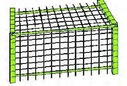
The finite element model for the steel rack analysis is shown on Figure 1. The same model segment could be repeated axisymmetrically to form a continuous rack 360 degrees around the containment. Because the structures of each section are identical, only one section is modeled using the GT-STRUDL program (Ref. 3).
3.1 GT-STRUDL Model
Copyright © 2005 by SMiRT18 the steel bar assemble) is assumed to act on both the top and front faces of the rack simultaneously. This assumed load represents the worst single loading case (impact load). A static structural analysis and an eigenvalue (natural frequency) calculation are performed, and the results are used to calculate the structural ductility ratio.
Figure 1. Steel rack FEA model
3.2 Ductility Ratio Calculation
The member containing the maximum normal stress (from GT STRUDL analysis) is used to calculate the ductility ratio. This study has been prepared using ASTM A36 and A500 Grade B steels as an example, which are both the potential materials to build the steel rack. The main steps are shown below. The values shown in the diagrams are from the design example, in which the maximum stress is 155 ksi. The yield stress is 36 and 46 kips per square inch (ksi) for A36 and A500 Gr B steel, respectively.
1. Yield strain.
Per Ref. 4, Part 6, "Effect of Heat on Structural Steel", the yield stress of ASTM A36 and ASTM 500 Grade B materials does not vary significantly for temperature changes within the 300 to 700 oF range, which covers the temperature variation during accident conditions inside the reactor building containment area. From yield stress, yield strain can be calculated as follows:
(Eq. 1) y
y
ε =
E σ
where:
ε
y= yield strain
σ
y= yield stressE = modulus of elasticity
2. Strain based on elastic deformation.
(Eq. 2)
e σ
ε =
y m y σ
ε .
where:
ε
e= elastic strain
σ
m= elastic stress, maximum3. Energy stored beneath the elastic stress/strain curves (Figure 2).
(Eq. 3)
. m e stored
E =
ε
σ
2
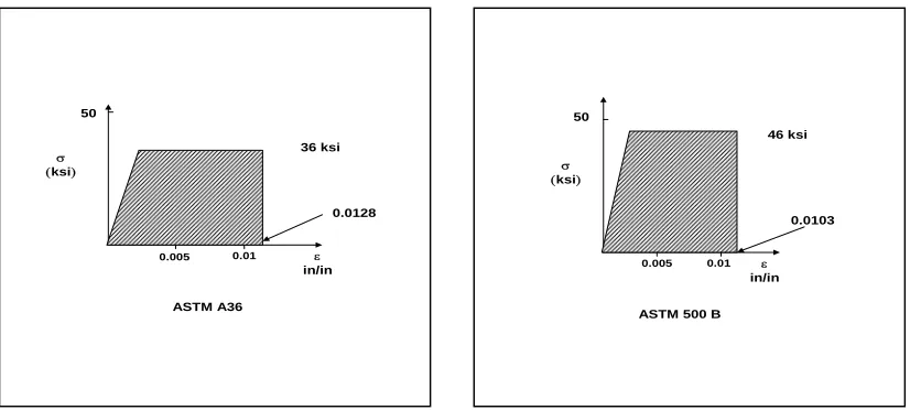
4. Actual strain obtained from the energy stored (Figure 3).
(Eq. 4) y
y stored
E
+
(
)
y
true
σ
ε
σ
ε
2
.
=
σ (ksi)
0.0025 0.005
50 100
36 ksi σ
ε
ε in/in 155 ksi
ASTM A36
0.0056
σ (ksi)
0.0025 0.005 50
100
46 ksi
σ
ε
ε
in/in 155 ksi
ASTM 500 B
0.0056
Figure 2. Elastic strain based on elastic deformation
50
σ (ksi)
0.005 0.01 ε in/in
ASTM A36
0.0128 36 ksi
50
σ (ksi)
0.005 0.01 ε in/in
ASTM 500 B
0.0103 46 ksi
Figure 3. Actual strain based on deformation energy
5. Ductility ratio for the flexural member.
(Eq. 5) true
ε µ =
y
Copyright © 2005 by SMiRT18 3.3 Equivalent Static Load Assessment
The following analysis evaluates the impact effect of a high-velocity fragment striking the steel rack. The loading on the steel rack is in the nature of an impulse. This impulse loading needs to be converted into an equivalent static load for design purposes. To use the equation suggested by R. A. Williamson and R. R. Alvy (Ref.1) to calculate the equivalent static load, the energy loss during the collision needs to be considered. The energy loss coefficient
φ
as a modification is introduced in this study and described in the following.1. Energy loss
As soon as the postulated fragment hits the steel rack (steel bars), the bars start to deflect (have speed). The kinetic energy brought by the fragment (before impact) is partially transferred to the structure and remains partially in the fragment. An amount of energy is consumed during the collision. It is been converted into other forms of energy, such as heat, deformed energy, friction energy, etc. In other words, not all the kinetic energy brought with the fragment is transferred into the steel rack. The portion that is not transferred is called “energy loss” and is estimated as follows (Ref. 6).
Definition:
m1: mass of the projected fragment.
m2: mass of the deformed part of steel rack, including steel bars and steel angles. V1: velocity of the projected fragment before impact.
V2: velocity of the projected fragment and steel rack after impact (assume it is a plastic impact).
From the Conservation of Momentum Principle:
m
1V
1=
(
m
1+
m
2)
V
2 (Eq. 6)Kinetic energy before impact: 2 1 12
1
1
m
V
E
=
(Eq. 7)Kinetic energy after impact: 2 1 2 22
1
2
(
m
m
)
V
E
=
+
(Eq. 8)From Equ. (6), the velocity after impact: 1
2 1 1 2
V
m
m
m
V
+=
Kinetic energy after impact becomes: 12
2 1 2 1 2
2
1
V
m
m
m
E
+=
Energy lost during impact ∆E=E1-E2:
2 1 2 1 2 1 2 m m
m m V E + =
∆ (Eq. 9)
The ratio of energy lost to the energy before impact:
2 1
2
1 m m
m
E E
+
=
∆ (Eq. 10)
2. Static equivalent load
In general, the projectile velocity and weight are estimated from a postulated pipe break accident. The design parameters used in this example and the structural analysis results from GT-STRUDL output (impact load) are listed below. Note that only the last iteration step parameters are shown.
Fragment velocity: v = 50 mph
Fragment weight: w1 = 44 lb
Rack deflection: X = 5.17 in.
Rack natural frequency: f = 1 2.3 Hz
Rack steel ductility ratio: µ = 9.65 (calculated from Section 3.1)
t 1 2 X.v
Duration of impact:
Natural period of vibration: T=0.08 sec
Assumed impact area: A=5.38 ft2
Deformed steel rack weight: w2 = 90 lb
∆E %( ) 1 w 1
w 1 w 2
Energy loss ratio (%): ∆E %( ) =67 %
Kinetic energy after impact
φ
= 1 -∆
E (%) φ =0.33 within steel rack & fragment (ratio):To consider the energy loss during impact, a factor of reduction is used in the calculation of equivalent static load in Equ. 8 below.
φ
Equivalent Static Load: (Eq. q y µ . 1 1 1 2 2. 11) 2.µ 1 w 1
2.µ
µ2
π . .v
g T.
. φ
.
The equivalent static load: q y 1060.8 lb=
Equivalent static pressure: p r =1.37 psi
In this example, the input of the GT-STRUDL analysis is 1.1 psi. As mentioned in Ref. 2, when an equivalent static load is used to estimate the impact effect of a missile striking a steel structure (without penetration) at high velocity, "The computed equivalent static load may be off by as much as a factor of two from the true value". Therefore, the computed equivalent static load of 1.37 psi is within the accuracy range for the design load (pressure).
4. RESULT AND DISCUSSION
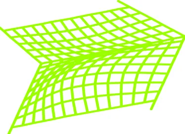
The evaluation reveals that the steel rack is structurally qualified for a 1.1 psi static pressure. Such static pressure has been reconciled as equivalent to the design basis impact load (load case 1 in Section 2.1). The pressure applies on an “impact area” and is assumed to act at the worst locations of both the top and front sides simultaneously. Such “impact load” has been combined with “OBE+LOCA+SRV” and “SSE+LOCA+SRV”, respectively. The final steel rack structural design meets all the requirements of the design criteria.
Figure 4. Deformed steel rack under the impact load
Copyright © 2005 by SMiRT18
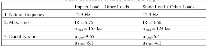
Table 1: Results of Analysis and Design
Impact Load + Other Loads Static Load + Other Loads
1. Natural frequency 12.3 Hz. 12.3 Hz.
2. Max. stress IR = 5.75 IR = 4.60
σmax = 155 ksi σmax = 124 ksi
3. Ductility ratio µA36=9.65 µA36=6.4
µA500=6.1 µA500=4.1
From Table 1, the “Impact Load + Other Loads” case is the governing design load case. The highest ductility ratio (for both materials) is 9.65. Since the steel rack is a safety-related structure, the regular AISC N690 (Ref. 5) allowable ductility ratio shall be replaced by the USNRC SRP 3.5.3, Appendix A (Ref. 2). The permissible ductility ratio for overall damage prediction in structural steel members is µ=10.0 for tension due to flexure. The steel rack members are deemed satisfactory under the debris impact, plus other loads, from LOCA.
5. CONCLUSIONS
The method described in this paper is for overall damage evaluation of a steel structure under impact loading (without penetration). As reviewed in the discussion, the response of such structures to missile impact depends on the location of impact, dynamic properties of the structure, and the amount of the kinetic energy of missile. For a plastic collision, this method gives a reasonably equivalent static design load. This load can be used in conventional structural design methods.
6. REFERENCES
1. R. A. Williamson and R. R. Alvy, "Impact Effect of Fragments Striking Structural Elements". Holmes and Narver Inc. Revised November 1973.
2. US Nuclear Regulatory Commission, “Standard Review Plan”, Section 3.5.3, Appendix A. Revision 1, July 1981.
3. GT STRUDL, User’s Manual, Version 27
4. AISC, Manual of Steel Construction, Allowable Stress Design, Ninth Edition, 1989.
5. ANSI/AISC - N690, Nuclear Facilities – Steel Safety Related Structures for Design, Fabrication and Erection, 1984.
6. Timoshenko and Young, Engineering Mechanics, 2nd Edition Article 78.
7. ACKNOWLEDGEMENT
The author would like to thank Mr. Enrique R. Solorzano for the discussions we had during the development of this methodology. His help is highly appreciated.