The Optimized Stream Cipher using the
MOWG Transformation based on the
Montgomery Multiplication Algorithm
Ashly Paul, Betsy Jose
M.Tech Scholar (VLSI &Embedded System), Dept. of ECE, IIET, M.G University Kottayam, Kerala, India
Assistant Professor, Dept .of ECE, IIET, Nellikuzhy, Kerala, India
ABSTRACT: The multiple outputs WG (MOWG) version is a new hardware design of the Welch–Gong (WG) cipher. Through signal reuse technique the proposed MOWG reduces the number of field multipliers and eliminating two inverters delay in the transformation. It accomplished by reconstructing the key and initial vector loading algorithm and feedback polynomial of the LFSR. And the MOWG transformation is modified with modular Montgomery multiplier based on the Montgomery multiplication algorithm. The Montgomery Multiplication algorithm is a standard arithmetic because it can perform modular multiplication without the trial division. It is the most efficient solution for the design of a fast architecture and VLSI implementation. The field programmable gate array implementation of this proposed design shows the area, delay and the power consumptions.
KEYWORDS: Multiple output WelchGong (MOWG) transformation, linear feedback shift register (LFSR), stream ciphers, finite state machine (FSM), Montgomery multiplication algorithm, finite fields.
I. INTRODUCTION
A synchronous stream ciphers are the lightweightsymmetric-key consist of a key stream generator which produces a sequence of binary digits. This sequence is called the key stream. This key stream is xored to the plain text to produce the cipher text [1]. The key stream bits are produced to using the pseudorandom sequence generator and a secret key. A new synchronous stream cipher called the WG cipher based on the WG transformation. The WG cipher has been designed to produce the key stream with guaranteed randomness properties like balance, long period, linear complexity etc and it also offers the high level security [2]-[3]. In addition, the WG cipher is secure against the algebraic attacks [4].
A new multiple-bit output version of the WG cipher is called multiple outputs WG (MOWG). This version is the word bit oriented stream cipher. The MOWG reduces the hardware and software complex through the signal reuse by removing one multiplier from the WG permutation, and it generates the greater than or equal 17 output bits. The key stream sequences are generated by the MOWG cipher occurs many of the WG key stream randomness properties [5].
We propose a low complex MOWG transformation using the Montgomery multiplier, based on the Montgomery multiplication algorithm [6]. The Montgomery Multiplication algorithm is proven that the algorithm is also accurate in the Finite Field arithmetic. This architecture is optimized to minimize the silicon covered area and reduce the
multiplication time delay.
II. RELATED WORKS
Krengel uses a look-up based fast WG stream cipher approach that uses 229 bits of ROM [3]. But it has a complex structure and time consuming.
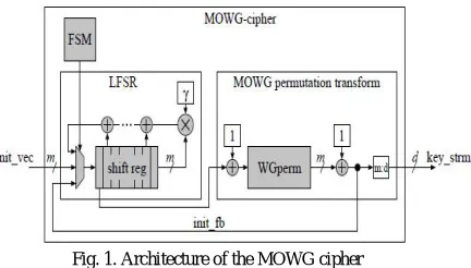
Then after C. Lam et al., the authors are proposed the multiple-bit output version of the WG cipher, called multiple outputs WG (MOWG) [5]. This MOWG removing one multiplier from the WG permutation to reduce the hardware cost through signal reuse, whereas it generates the word bit oriented cipher. Furthermore, it improves the throughput of the cipher through the pipelining with reuse techniques. The MOWG ciphers are implemented with LFSRs ranging from 5 to 23 stages. The MOWG ciphers are regarding in the form of nonlinear filter. A MOWG cipher shows in the fig.1 consists of a linear feedback shift register, followed by a MOWG permutation transform.
Fig. 1. Architecture of the MOWG cipher
Fig. 1(a) shows a detailed version of the high-level architecture of the MOWG cipher. The finite state machine controls the operations of the phase during the cipher in load key and initial vector, initialize, and run. The number of stages in the LFSR and the latency through the WG permutation are determined depends on the duration of each phase. The FSM has implemented with an l-bit one-hot counter and a 2-bit binary counter for the phase operations. The key and initial vector loading phase lasts the clock cycles which inputting the LFSR is init vec. The initialization phase last clock cycles which inputting to the LFSR is becomes the XORed value of the LFSR feedback and init fb from the WG-permutation. During the run phase, init fb does not used. It enables the WG-permutation for the deeply pipelining. There are seven multipliers and inverters based on the optimal normal basis. It conducts the hardware complexity for the implementations of the design. So we propose a design to avoiding the optimal normal basis multiplier, and using the Montgomery multiplier [6].
III.OPTIMIZED HARDWARE DESIGN OF THE MOWG TRANSFORMATION
The transform’s field multipliers depend on the hardware cost of the MOWG cipher. The area of the overall cipher
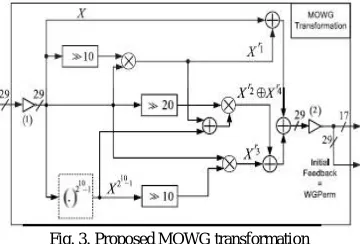
will be minimizing with decrease in the number of these multipliers. This section presents the architecture of the MOWG transform, where the number of field multipliers is reduced by 1 through signal reuse compared with [5]. In the MOWG (29, 11, 17) transformation using four multiplications and four squaring operations. The inverter (1) requires 29 NOT gates. In Fig. 2, the output of X^Xr1^Xr2^Xr3^Xr4 in GF (229) are complemented by the inverter (2) to generate all 29 bits of the WG Permutations which forms the initial feedback. Seventeen bits of the WGPerm are the output of the MOWG in the run phase. To reducing the hardware complexity using the modular Montgomery multiplier instead of the normal base multiplier. The Montgomery Multiplication algorithm can perform modular multiplication without trial division. And this algorithm is also accurate in Finite Field arithmetic.
A. The Montgomery Multiplication Algorithm for GF(2k) fields:
The modular arithmetic operations have a division is needed in order to get the remainder. So the division is very
complex, time consuming operation in GF (2k) fields. Therefore a algorithm is taken from the standard arithmetic, is the
Montgomery Multiplication Algorithm [6]-[9]. It performs modular multiplication without division. This algorithm is
also accurate in the Finite Fields arithmetic [7]. Instead of a(x)b(x)mod f(x) the algorithm calculates a(x)b(x)r-1(x) mod
f(x) where r(x) is the recomputed value, r(x) = xk. If correctly choosing the r(x) value, the algorithm becomes less
complex and efficiently in hardware implementations. So, for r(x) = xk the bit level algorithm [7] has showing below;
Input: a(x),b(x), f (x)
1. c(x) = 0
2. For i=0 to k-1 do begin
3. c(x) = c(x) + ai b(x)
4. c(x) = c(x) + c0 f(x)
5. c(x) = c(x)/ x End
6. Return c(x)
The Montgomery Multiplication algorithm has conducting the k-times loop of two field additions, two multiplications and a division by x. And its VLSI gates logic are translated in two XOR actions, two AND actions and a simple 1bit shift.
Fig. 2. Architecture of the multiplier using Montgomery algorithm
The Montgomery algorithm means that step 4 of the Montgomery Multiplication Algorithm, the k-th bit of the sum C(x) is set to 1, if c0 is set to 1. And in the case of step 5, the MSB of the output C(x) is set to 1, if c0 of step 4 is set to 1. So this algorithm is modified as shown in the Fig. 2 [9]. Here the final shift operation is done through a rearrangement of wires. And also the k-bit numbers are used since the k-th bit of F is not needed. So this multiplier can reduce the hardware complexity of the transformation.
B. The Proposed MOWG Transformation:
The delay of the overall cipher is depends on the time delay of the MOWG transform. So arranging the transformation becomes slightly to reduce the delay. This is occurred by removing the inverter 1, and reallocating the inverter 2 away from the critical paths of the key initialization phases. This procedure reduces the critical path delay with an amount equivalent to the delay of two inverters. And also the MOWG transform delay is dominated with the delays of the Montgomery multipliers.
Fig. 3. Proposed MOWG transformation
realizes the addition of the field element 1 in the WG permutation. Then to add the one of the terms X, Xr1, Xr2 ^Xr4, or Xr3 before the summation of these terms [10]. Reallocate the inverter 2 from its current position. However, it required that the reallocation does not happen in the delay higher than the current maximum delay of the MOWG transform. Because of the inverter is relocated to complement the X before it is added to Xr1. This path is shows at the top of the Fig. 3, which has the lowest delay of the two GF(229) adders between inverters 1 and 2.
IV.ARCHITECTURE OF THE MOWG STREAM CIPHER
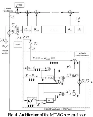
In the key initialization algorithm, the MOWGs LFSR is requiring to modifying the left most stage of the LFSR to hold the complement of the initial vector during the loading phase. So, before it loaded to the modified LFSR is required to complement the initial vector input. It can be implemented by inserting the 29 inverters at the multiplexer have input that receives the initial vector.
Fig. 4. Architecture of the MOWG stream cipher
The proposed architectureof the MOWG (29, 11, 17) stream cipher is shown in theFig. 4. In this figure, during the
each phase of operation is controls the FSM by the input to theLFSR. Then the loading phase theLFSR receives the complemented initial vector through the bit wise complimented input. Then after the 11 clock cycles, the initial state of this LFSR, (B0, B1, . . . , B10), is complemented the initial state of the LFSR , i.e., Bi = Ai ^1, 0 ≤ i < 11. During the key initialization phase starts, the input of the LFSR is applied with the bit-wise XOR of the initial feedback and linear feedback, which is equivalent to Bi = Ai ^1, 11 ≤ i < 33 [10]. During the running phase, the linear feedback signal Bi = Ai ^ 1, 33 ≤ i < 2319 – 1 is only input to the LFSR. These sets the MOWG transform of Fig. 4 to generate the same key-stream bits of the Fig.3. However, the maximum delay of the MOWG transformation has been decreased by an amount equivalent to the delay of two inverters.
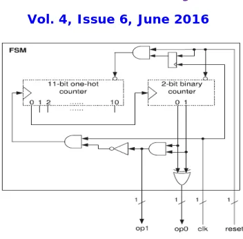
A. Finite state machine
Fig. 5. FSM of the MOWG stream cipher
The 11-bit one-hot counter is to initialize the (1, 0, . . . , 0). So the output op0 bit is only set to a high logic level state. The 2-bit binary counter is resets its state to (0, 0) if the rst signal becomes in low condition. The input of the 11-bit one-hot counter is reset through the AND gate becomes connected to the 1 11-bit register. And this counter starts to incrementing one clock cycle after the reset signal gets in pulled up condition. This occurs the 11-bit one-hot counter is returns to its initial state after the 11 clock cycles. Then after the initialization phase has been started to incrementing when it triggers the 2-bit binary counter. And the output of the 2-bit binary counter is controls the phase operations of the cipher.
Table. 1. Phase of operation as a function of the state of the 2-bit binary counter
bit 1 bit 0 op 1 op 0 Phase of operation
0 0 0 0 load key and iv
1 0 0 1 key initialization
0 1 0 1 key initialization
1 1 1 0 running phase
The three inputs of the multiplexer are selected in the basis of the signals op0 and op1 that shows in the Fig. 4. And during the each phase it connected to the input of the LFSR. It is means that the 11 clock cycles takes under the loading phase, and the key initialization phase starting takes 22 clock cycles, followed by the run phase operation. During the running phase, the idle case is occurred in the clock inputs of the 11-bit one-hot counter and the 2-bit binary counter. This is done by generating the op0 and op1 output signals according to Table 1.
V. SIMULATION RESULTS
To compare the performance of the MOWG cipher design with that of previous paper, we implement the modified MOWG cipher with Montgomery multiplier. So we can reduce the delay, area and power consumption. The simulation and implementation results of previous MOWG stream cipher are shown below. The waveform from the Model Sim is provided below. And the comparison results from the Xilinx synthesized results have obtained.
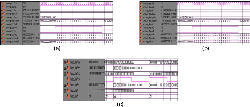
The simulation result of MOWG encryption is shown in fig 6 (a). Here plain, iv, key and reset are the inputs and clk is the clock signal. The iv and key are 128-bit and plain text is 17-bit input value have loaded. Cipher is the 17-bit cipher text as the output value as shown in ASCII codes. The cipher text is obtained after loading the 44 clock cycles. This clock cycle is operate depends on the FSM. FSM have 11-bi1 ring counter and 2-bit counter. C0, c1 are the output of the FSM. If c0 = 0 and c1 = 1, in this condition the running phase is operated. During the running phase MOWG transformation is started to generate key and that key is xored with plain text to get cipher text.
(a) (b)
(c)
Fig .6. Simulation Result of (a) MOWG encryption (b) MOWG decryption (c) Normal basis multiplier in the MOWG transformation
The simulation result of MOWG decryption is shown in fig 6(b). Here cipher, iv, key and reset are the inputs and clk is the clock signal. The iv and key are 128-bit and cipher text is 17-bit input value have loaded. Plain is the 17-bit plain text as the output value as shown in ASCII codes. The simulation result for the normal basis multiplier used in the MOWG transformation as shown in fig 6(c). Here ‘a’ and ‘b’ are the input signals to be applied. And ‘out’ is the output result of the multiplier. This multiplier result is computed for the MOWG transformation. Here applying the signal ‘e’ as constant hex value 0XFFFFFFF8. This normal basis multiplier has the complex structure.
The simulation result of modified MOWG encryption is shown in figure 7 (a). Here plain, iv, key and reset are the inputs and clk is the clock signal. The iv and key are 128-bit and plain text is 17-bit input value have loaded. Cipher is the 17-bit cipher text as the output value as shown in ASCII codes. The cipher text is obtained after loading the 44 clock cycles. This clock cycle is operate depends on the FSM. FSM have 11-bi1 ring counter and 2-bit counter. C0, c1 are the output of the FSM. If c0 = 0 and c1 = 1, in this condition the running phase is operated. During the running phase MOWG transformation is started to generate key and that key is xored with plain text to get cipher text.
(a) (b)
(c)
Fig .7.Simulation Result of (a) modified MOWG encryption (b) modified MOWG decryption (c) Modular Montgomery multiplier in the MOWG transformation
The simulation result for the modular Montgomery multiplier used in the MOWG transformation as shown in fig 7 (c). Here ‘ina’ and ‘inb’ are the input signals to be applied. And ‘out’ is the output result of the multiplier. This multiplier result is computed for the MOWG transformation. Here ‘f’ value is the constant value as 1. And the output is coming after the 29 count becomes presented.
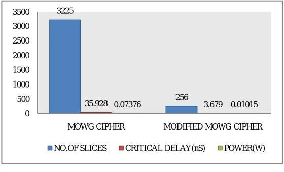
Table. 2. Comparison table of different cipher
Table.2 shows that the area, power and delay specifications. The area is described according to the number of the
slices. Here MOWG have more conducting the area but it has better delay contained. During run phase of the MOWG,
17 output bits are generated. The maximum propagation delayis equivalent to 17 levels of gate delays. So the delay is reduced in the case of modified cipher. And also the power consumption has complex than the modified MOWG cipher. The fig. 8 shows that, the area, delay and power is more in the case of modified MOWG cipher than the MOWG cipher. So the modified MOWG cipher has better results with the area, delay, and speed specifications.
Fig. 8. Comparison Chart of Different ciphers
Themodified MOWG design reduced thehardware cost in the MOWG transformation by removing the multiplier
and adding the modular Montgomery multiplier. The corresponding throughput and running phase latency of the cipher are 17/(TA + 6TX ) and 6 (TA + 6TX), respectively. Because of the [5] have 46 levels of logic gate delays, so, the throughput of the proposed MOWG is almost six times higher operation. The optimized MOWG reduces the number of field multipliers in the transform by signal reuse. So it increases the speed by eliminating two inverters delay from the critical path in to the transformation. This is conducted by reconstructing the key initialization algorithm and feedback polynomial of the LFSR.
VI.CONCLUSION
The previous design conducts the complex multipliers in to the MOWG transformation. So we have to need for
reducing the operation in to the transformation module. Further, the advanced efficient types of multipliers are used. So we modified the modular Montgomery multiplier instead of the normal basis multiplier used in MOWG transformation. It becomes more efficient and serialized the output bits such as cipher text and plain text during the encryption and
Design No. of slices
Delay(nS) Power(w)
MOWG cipher design 3225 35.928 0.07376
modified MOWG cipher design
256 3.679 0.01015
3225
256
35.928 0.07376 3.679 0.01015 0
500 1000 1500 2000 2500 3000 3500
MOWG CIPHER MODIFIED MOWG CIPHER
decryption respectively. And it reduces the complexity of the MOWG transformation. It performs modular
multiplication without the division operation. The algorithm is also accurate in the Finite Fields arithmetic. The
Montgomery Multiplication Algorithm for Finite Fields have getting the very promising results in terms of
multiplication time delay, clock frequency and chip covered area. This makes the architectures very useful in the
applications like Elliptic Curve cryptography, 4G mobile technology, Bluetooth, RFID tag, network protocols etc. And
also it is a very efficient solution for thedesign of a fast architecture and VLSI implementation.
REFERENCES
1. Y. Nawaz and G. Gong, “WG: A family of stream ciphers with designed randomness properties,” Inf. Sci., vol. 178, no. 7, pp. 1903– 1916, 2008.
2. G. Gong and Y. Nawaz. (2005). The WG Stream Cipher [Online]. Available: http://www.ecrypt.eu.org/stream/wgp2.html
3. E. Krengel, “Fast WG Stream Cipher,” in Proc. IEEE Region 8 Int. Conf. Comput. Technol. Electr. Electron. Eng., Jul. 2008, pp. 31–35. 4. A. Mirzaei, M. Dakhilalian, and M. Modarres-Hashemi, “An Improved Attack on WG Stream Cipher,” Int. J. Comput. Sci. Netw.
Security, vol. 10, no. 4, pp. 45–52, Apr. 2010 [Online]. Available: http://paper.ijcsns.org/07_book/201004/20100408.pdf
5. C. Lam, M. Aagaard, and G. Gong, “Hardware implementations of multi-output Welch-Gong ciphers,” Dept. Department of Electr. Comput. Eng., Univ. Waterloo, Waterloo, ON, Canada, Tech. Rep. CACR 2011-01, 2009 [Online].
6. Peter L. Montgomery, “Modular multiplication without trial division,” Mathematics of Computation, vol. 44, no. 170, pp. 519-521, 1985. 7. C. K. Koc and T. Acar, “Montgomery Multiplication in GF(2k)”, in Proc. Of Third Annual Workshop on Selected Areas in Cryptography,
Ontario Canada, August 1996, pp. 95 – 106.
8. Huapeng Wu, “Montgomery Multiplier and Squarer for a class of Finite Fields”, IEEE Transactions on Computers,, vol. 51, no. 5, pp 521 – 529, May 2002.
9. A. P. Fournaris and O. Koufopavlou, “GF(2k) multipliers based on Montgomery multiplication algorithm”.
10. Hayssam El-Razouk, Arash Reyhani-Masoleh, and Guang Gong, “New implementation of the WG stream cipher”, IEEE Transactions on very large scale integration (VLSI) systems, vol. 22, no. 9, September 2014
BIOGRAPHY
Ashly Paul is an M-Tech scholar in VLSI and Embedded System in the Electronics and Communication Department, IIET, M. G. University. She received B-Tech degree in 2014 from M. G. University, Kottayam, Kerala. Her research interests are VLSI and HDL languages etc.