IJEDR1501088 International Journal of Engineering Development and Research (www.ijedr.org) 495
MATHEMATICAL MODELING OF OPEN LOOP
PMDC MOTOR USING MATLAB/SIMULINK
1
Mr.Dhaval K.Patel
1
Assistant Professor, Dept. of Electrical Engineering.
Gidc Degree Engineering College Abrama, Navsari.
__________________________________________________________________________________________________
ABSTRACT: Linear Dynamical models of physical systems One of the most used actuators in control systems is a direct current (DC) motor. The general output variable of this actuator can be angular speed or angular displacement motion, but, coupled with wheels or drums and cables, can provide translation motion. This paper proposes a state space model of the DC motor built for constant flux and considering two inputs: supply voltage and resistive torque. The two states of the resulting model are represented by angular speed and step response any of these states can be an output variable for a simulation model. Consequently, the system's model has two inputs and two outputs. For the system's simulation a VI is built where the most important element is a Matlab script which contains the matrices A, B, C, D of the state-space model, the independent variable time and the Matlab simulation function. The motor's parameters are given by digital controls on the panel so that these parameters can be interactively modified. To generate inputs, two case structures are used where the input variables can be set: impulse, step and ramp. Here it is also possible to set the signal amplitude and duration, either by step input or torque N.m. The output signals are live display, either one by one or together, on the WAVEFORM GRAPH.
KEYWORDS: DC Motor, Out Put Response Analysis, MATLAB/SIMULINK.
__________________________________________________________________________________________________
1.0 INTRODUCTION
Direct-current (de) motors are one of the most widely used prime movers in industry today. Years ago, the majority of the small servomotors used for control purposes were ac. In reality, ac motors are more difficult to control, especially for position control, and their characteristics are quite nonlinear, which makes the analytical task more difficult. DC motors, on the other hand, are more expensive, because of their brushes and commutators, and variable-flux de motors are suitable only for certain types of control applications.
Before permanent-magnet technology was fully developed, the torque per unit volume or weight of a de motor with a permanent-magnet (PM) field was far from desirable. Today, with the development of the rare-earth magnet, it is possible to achieve very high torque-to-volume PM de motors at reasonable cost. Furthermore, the advance made in brush-and-commutator technology have made these wearable parts practically maintenance-free. The advancements made in power electronics have made brushless dc motors quite popular in high-performance control systems. Advanced manufacture techniques have also produced dc motors with ironless rotors that have very low inertia thus achieving very high torque-to-inertia ratio. Low-time-constant properties have opened new applications for dc motors in computer peripheral equipment such as tape drive printers, disk drives, and word processors, as well as in the automation and machine-t industries.
1.1 DC MOTORS IN CONTROL SYSTEMS
In laboratory for academician, the model and the Voltage(V) and current (I) in the classroom to simulate the running of a DC motor and also to learn how to incorporate the latter into a control loop. To start with, based on a functionality structure of the DC motor and on the laws of physics and electricity that rule the motor's operation, students build a mathematical model. Afterwards, using the mathematical model in a series of simulation experiments in Direct-current (dc) motors are one of the most widely used prime movers in industry today. Years ago, the majority of the small servomotors used for control purposes were ac. In reality, ac motors are more difficult to control, especially for position control, and their characteristics are quite nonlinear, which makes the analytical task more difficult.
The dc motor is basically a torque transducer that converts electric energy into mechanical energy. The torque developed on the motor shaft is directly proportional to tie fie flux and the armature current. Since dc motor are used extensively in control system, it is necessary to establish mathematical model for analytical purpose dc motor for controls applications.
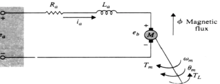
IJEDR1501088 International Journal of Engineering Development and Research (www.ijedr.org) 496 Figure 1. EQUIVALENT MODEL OF A SEPARATELY EXCITED DC MOTOR.
1.2 Mathematical Modeling of PM DC Motors Functionality Equations: -
Since dc motor are used extensively in control system, it is necessary to establish mathematical model for analytical purpose dc motor for controls applications. We use the equivalent circuit diagram in Fig. 1. to represent a PM dc motor.
The armature is modeled as a circuit with resistance
R
a
connected in series with an inductanceL
a
,
and a voltage sourcee
a
,
e
b
representing the Back-Emf (electromotive force) in the armature when the rotor rotates. The motor variables and parameters are defined as follows:e
a
(t)
= Applied voltage
e
m
(t)
= Rotor displacement
R
a
= Armature resistance
K
t
= Torque constant
i
a
(t)
= Armature current
K
b
= Back-emf constant
L
a
= Armature inductance
Φ
= Magnetic flux in the air gap
e
b
(t)
= Back emf
w
m
(t)
= Rotor angular velocity
T
L
(t)
= Load torque
J
= Rotor inertia
T
m
(t)
= Motor torque
B
m
= Viscous-friction coefficient
With reference to the circuit diagram of Fig. 1, the control of the dc motor is applied at the armature terminals in the
form of the applied voltage
e
a
(t).
For linear analysis, we assume that the torque developed by the motor is proportional to the air-gap flux and the armature current.
T
m
(t)
=
K
m
(t) ×
Φ
×
i
a
(t)
IJEDR1501088 International Journal of Engineering Development and Research (www.ijedr.org) 497
Since
Φ
is constant, Eq. (1) is written as,T
m
(t)
=
K
t
(t) ×
i
a
(t)
……. (2)
Where,
K
t
is the torque constantin N-m/A, lb-ft/A, or oz-in/A.Starting with the control input voltage
e
a
(t)
,
the cause-and-effect equations for the motor circuit in Fig.-1 are:e
a
(
t)
=
R
a
i
a
(t)
+
L
a
𝒅𝒊
𝒂
𝒅𝒕
+
e
b
(t)
..…….(3)
T
m
(t)
=
B
m
w
m
(t)
+
J
𝒅
𝒘
𝒎
(𝒕)
𝒅𝒕
+
T
L
(t)
..…….(4)
T
m
(t)
=
K
t
(t) ×
i
a
(t)
…….. (5)
e
b
(t
)
=
K
b
(t)
𝒅𝜽
𝒎
(𝒕)
𝒅𝒕
=
K
b
(t)
w
m
(t
) ..…….(6)
Where
T
L
(t)
represents a load frictional torque such as Coulomb friction. Consider that the applied voltagee
a
(
t)
is the cause; Eqn. (3) considers that𝒅
𝒊
𝒂(𝒕)
𝒅𝒕
is the immediate effect due toe
a
(
t)
;
In Eqn. (2)𝒊
𝒂
(𝒕)
Causes the torque
T
m
(t
)
;
Eqn. (6) defines the back emf; and, finally, in Eqn. (8), the torque
T
m
(t
)
causes the angular velocityw
m
(t)
For modeling purposes it is often convenient to derive a state-space representation of a motor. Eqn. (3) and (4) are rewritten as,𝒅𝒊
𝒂
(𝒕)
𝒅𝒕
=
−
𝑹
𝒂
𝑳
𝒂
𝒊
𝒂
(𝒕) −
𝟏
𝑳
𝒂
𝒆
𝒂
(𝒕) −
𝟏
𝑳
𝒂
𝒆
𝒃
(
𝒕
)
=
−
𝑹
𝒂
𝑳
𝒂
𝒊
𝒂
(𝒕) −
𝟏
𝑳
𝒂
𝒆
𝒂
(𝒕) −
𝑲𝒃
𝑳
𝒂
𝒘
𝒎
(
𝒕
)
……. (7)
𝒅𝒘
𝒎
(𝒕)
𝒅𝒕
=
𝟏
𝑱
𝑻
𝒎
(𝒕) −
𝟏
𝑱
𝑻
𝑳
(𝒕) −
𝑩
𝒎
𝑱
𝒘
𝒎
(𝒕)
=
𝑲
𝒕
𝑱
𝒊
𝒂
(𝒕) −
𝟏
𝑱
𝑻
𝑳
(𝒕) −
𝑩
𝒎
𝑱
𝒘
𝒎
(𝒕)
…… (8)
IJEDR1501088 International Journal of Engineering Development and Research (www.ijedr.org) 498
[
𝒅𝒊
𝒂(
𝒕
)
𝒅𝒕
𝒅𝒘
𝒎(
𝒕
)
𝒅𝒕
]
= [
−
𝑹
𝒂
𝑳
𝒂
−
𝑲
𝒃
𝑳
𝒂
𝑲
𝒕
𝑱
−
𝑩
𝒎
𝑱
] × [
𝒊
𝒂
(
𝒕
)
𝒘
𝒎
(
𝒕
)
] + [
𝟏
𝑳
𝒂
𝟎
𝟎
−
𝟏
𝑱
] × [
𝒆
𝒂
(
𝒕
)
𝑻
𝑳
(
𝒕
)
]
Following are data of motor:
R
a
= 1
Ω
K
t
= 10 N*M
L
a
= 0.005H
J
= 2
K
b
= 0.1
B
m
= 0.5
2.0 MATLAB SIMULATION BLOCKS:
Figure 2. BLOCK DIAGRAM OF DC MOTOR
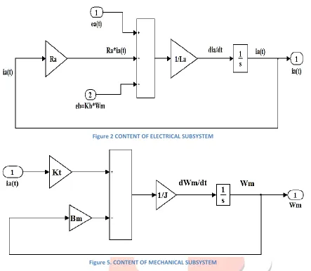
IJEDR1501088 International Journal of Engineering Development and Research (www.ijedr.org) 499 Figure 2 CONTENT OF ELECTRICAL SUBSYSTEM
Figure 5. CONTENT OF MECHANICAL SUBSYSTEM
Although a de motor by itself is basically an open-loop system, the diagram of Fig. 4 and the block diagram of Fig. 5 show that the motor has a "built-in" feedback loop caused by the back emf. Physically, the back emf represents the feedback of a signal that is proportional to the negative of the speed of the motor. As seen from Eq. (7 & 8), the back
emf constant
K
b
represents an added term to the resistanceR
a
and the viscous-friction coefficientB
m
. Therefore, the back-emf effect is equivalent to an "electric friction," which tends to improve the stability of the motor; and in general, the stability of the system.2.1 Relation between
K
t
andK
b
.Although functionally the torque constant
K
t
; and back-emf constantK
b
are two separate parameters, for a given motor their values are closely related. To show the relationship.we write the mechanical power developed in the armature as
P
=
e
b
(t) ×
i
a
(t)
……... (9)
The mechanical power is also expressed as,
P
=
T
m
(t) ×
w
m
(t)
……... (10)
IJEDR1501088 International Journal of Engineering Development and Research (www.ijedr.org) 500
we get,
P
=
T
m
(t) ×
w
m
(t) =
K
b
w
m
(t)
×
𝑻
𝒎(𝒕)
𝑲
𝒕……... (11)
from which we get,
K
b
(
V/rad/sec
)
=
K
t
(
N-m/A
)
Thus, we see that in SI units, the values of
K
b
andK
t
are identical ifK
b
is represented in V/rad/sec andK
t
is in N-m/A.3.0 Result
All The equation will be used in MATLAB / SIMULINK in to analyze speed response of the motor
Figure 6. INPUT AND OUTPUT RESPONSE OF THE MOTOR
4.0 APPLICATION
- In many industries such as paper mills, rolling mills, printing machine tools, excavators and cranes etc the dc motor is used for way a product from one place to another on the conveyer belt.
- Robotics arm for peak and place purpose. - In electrical lab purpose.
SOFTWARE used is MATLAB
5.0 REFERENCES
[1] A. FRANSUA, MASINI SI ACTIONARI ELECTRICE, TEHNICA, BUCURESTI (1986). [2] M. GHINEA, MATLAB: CALCUL NUMERIC-GRAFICA, TEORA, BUCURESÎTI (1997).
[3] D. MATKO AND R. KARBA, SIMULATION AND MODELLING OF CONTINUOUS SYSTEM, PRENTICE-HALL, NEW YORK (1992).
[4] SPEED AND DIRECTION CONTROL APPARATUS FOR DC MOTORS US 3,857,077 [5] DC MOTOR CONSTANT SPEED PWM CONTROL US 6,731,082 B2
BOOKS:
[1] B.L. THEREJA, A TEXT BOOK OF ELCTRICAL TECHNOLOGY” S. CHAND & COMPANY LTD, RAM NAGAR,
NEW DELHI.