IJEDR1401024 International Journal of Engineering Development and Research ( www.ijedr.org)
144
Low Power Laser Based Breath Detecting System
1
Savsani Deepkumar Mansukhlal,
2Hansaliya Rishit Nileshbhai,
3Kantaria Parth Ratilal
1M.Tech Student, 2M.Tech Student, 3M.Tech Student
1Department Of Electronics & Communication Engineering, Manipal University Jaipur, Rajasthan, India 2Department Of Electronics & Communication Engineering, Manipal University Jaipur, Rajasthan, India
3
Department Of Electronics & Communication Engineering, R.K University, Gujarat, India
1[email protected], 2[email protected] , 3[email protected]
________________________________________________________________________________________________________
Abstract— In this paper, A low-power Laser projector and a Webcam are used to design a monitor system for the body breath detection, which monitors and records the patient's breath and sends the information to the server. Our system consists of two parts in which the first part has a Webcam, which is used to capture the images of the reflection from a low-power laser projector and transmits it to a PC. For the second part, an image processing program using the temporal differencing algorithm is used to detect the reflective mark movement to determine the breath rate, installed in the PC. The low-power laser which we are using in this project is safe for the patients.
Index Terms — Embedded System, Laser Reflection, Breath Detection, Image Processing.
I.INTRODUCTION
The traditional ways of monitoring the breath rate involve contact with the human body . For example, for Impedance Pneumography, one side of the electrode, which is placed on the skin of the chest, sends a high-frequency current and concurrently uses the other side of the receiving electrode to receive the current changes that take place during a breathing cycle. The earlier methods require some sort of tying up or other contact with the body. Thus there is a need to design a method of breath detection that avoids contact with the human body.
Our design detects chest expansion and contraction in a way that is similar to the detection of a moving object by laser reflection . There are three major methods used to detect a moving object. First, “temporal differencing” is used to find the difference between two continuous image data and obtains the changes in the volume of a moving object .If the background variation is not great, this method works well. Second, “background subtraction” establishes the background of the images and then inputs one image after another in order to cancel the background and to obtain the moving object .This method, which produces a complete outline of moving objects, is very sensitive to changes in the environment because the background is established from the very beginning. Third, “optical flow” calculates moving locations in time to discern each pixel in the image.
After comparing these three methods we have used the image processing method with “temporal differencing” in our design . This method has a higher image processing speed and its use in the circuit board will not cause much of the complexity in the circuit. To enhance the accuracy of our detection system we measure the breath twice instead of a single laser reflection. This design provides more amplification of the chest contraction from the breath and reduces the system detection error.
II. OPERATION OF THE SYSTEM
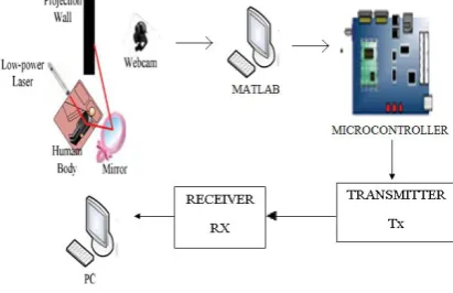
Fig 1 indicates block diagram. First we use a low power laser irradiating a patient’s chest with a smooth reflection surface and let the laser reflect this onto a mirror. Then two mirrors will reflect the laser ray twice onto the projection wall. Now we use the Webcam to monitor the laser projection. For home healthcare our design sends images captured by the Webcam to the embedded board which through digital image processing determines whether the breath rate is normal. The LCD displays the real-time status of the breath rate on the embedded board. If no signs of breath are detected, a warning message is sent to the hospital by the network. We use an embedded board instead of a PC because of its low power consumption and portability. In addition the embedded board reduces the cost, and one can use this system easily at home. It is thus convenient for home health application.
IJEDR1401024 International Journal of Engineering Development and Research ( www.ijedr.org)
145
III. USING THE METHODS
A. DIFFERENCING METHOD
The temporal differencing method which reads the continuous image from the Webcam, then fetches the separated image and processes it at the gray level. This method finds the subtraction of the continuous images, chooses the threshold value for the decision, uses a Gaussian filter to remove noise and then obtains the moving object.
B. MAGNIFICATION METHOD
When a patient breathes, the chest displacement is small. So we propose the laser reflection method to enlarge the displacement of the chest to detect the breath rate more easily[4]. Fig.2 shows the projection length of the moving object. X is the downward displacement of the chest which can be amplified by laser reflection onto a tilted wall. Y is the projection length of the first reflection. The magnification of the first reflection is shown in Eqn. (1).
𝑌
𝑋 = 2×(sin𝛾 𝑡𝑎𝑛(𝜃 + 𝛾) + 𝑐𝑜𝑠𝛾) (1)
Eqn.(1) shows the relationship between magnification and oblique angle of the wall which can provide a 10-times amplification if
𝜃 ≤ 75° and 𝜃 + 𝛾 ≥ 80°. When 𝜃 + 𝛾 ≥ 80°, the projecting point on the wall will be so far away that the laser ray will generate some distortion. The total magnification of the laser reflection is shown in Eqn. (2).
𝑍
𝑋 = 2×(sin𝛾 𝑡𝑎𝑛(𝜃 + 𝛾) + 𝑐𝑜𝑠𝛾)(sin𝜌 𝑡𝑎𝑛(𝜃 + 𝛾 + 𝜌) + 𝑐𝑜𝑠𝜌) (2)
By using Eqn.(1) and Eqn. (2) we learn that the total magnification is the multiplication of the first and second reflection’s amplification. To avoid distortion of the laser projection we arrange the first reflection to be enlarged by about 4.5 times when (𝜃 + 𝛾) ≥ 70° . Then we arrange 𝛿 ≥ 10° so that the second reflection can be enlarged more than 2.2 times. Therefore we reach our goal of the laser projection being enlarged by more than 10 times with less distortion. Fig 2 indicates Projection length of the chest displacement.
Fig2: Projection length of the chest displacement. IV. BREATH MONITORING
IJEDR1401024 International Journal of Engineering Development and Research ( www.ijedr.org)
146
determines the breath abnormalities. When the system detects no breath for more than 10 seconds, the system sends out a warning message. The judging method decides whether the patient’s condition is normal or not by detecting the breath rate.Fig3: Flowchart for determining breath abnormalities.
V. IMPLEMENTATION RESULTS
The implementation of the circuit, as it contains mainly four part power supply, microcontroller, switching circuit and transmission circuit. The basic block diagram of the circuit is shown below in Fig 4.,
Fig.4: Block Diagram
A. CALCULATION
After processing our program provides four data which show “Direction”, “Transition”, “Number of Breaths” and “Breath Rate”. “Direction” shows the direction of the thoracic movement which synchronizes with the chest moving targets in the area underneath the camera, “Transition” is the calculation of the cumulative transition, “Number of Breaths” calculates the accumulation of the breathing, and “Breath Rate” shows the immediate breath rate. The relationship is shown in eqns.
B. CASES
Figs. 5,6 & 7 show the three cases of breath displacement on the projection wall which demonstrates the chest expansion and contraction when the body breathes. The horizontal axis of the diagram is the time in seconds, and the vertical axis is the distance in centimetres on the projection wall. Denoted the transition when the directions of the two adjacent points in time are opposite each other. The Cases are given below about the breath displacement.
C. CASE 1
IJEDR1401024 International Journal of Engineering Development and Research ( www.ijedr.org)
147
Fig.5: Breath displacement diagram of Case 1,
D. CASE 2
Fig.6 shows the breath displacement diagram of Case 2, which has the same recording time of 60 seconds with about 12 full breaths. Here the respiratory rate is 11.6 full breaths per minute. Obviously the respiratory rate is one full breath less than in Case 1. This result indicates that although the observed respiration is slower, it still does not harm the body.
Fig.6: Breath displacement diagram of Case 2.
E. CASE 3
Fig.7 shows the breath displacement diagram of Case 3, which has the same recording time of 60 seconds with 8 full breaths. But as there are two breathing stops of over 5 seconds, the respiratory rate is 8 full breaths per minute. This result indicates not only slow breathing, but also that the amplitude of the chest movement is less, and that there is a cessation of breathing of over 5 seconds. The breathing of this individual, therefore, is already in a bad state.
Fig.7: Breath displacement diagram of Case 3. VI. FUTURE ENHANCEMENT
IJEDR1401024 International Journal of Engineering Development and Research ( www.ijedr.org)
148
VII. CONCLUSIONOur design uses the low-power laser reflection method to spot the variation in the breath and Webcam is used to capture the image, the temporal differencing method for breath detection and an embedded board to monitor the patient’s breath without the inconvenience to the body because of any physical contact by the instrument. This design detects chest expansion and contraction more easily. The additional cost is small for monitoring a patient’s breath in home healthcare.
REFERENCES
[1] K. P. Cohen, W. M. Ladd, D. M. Beams, W. S. Sheers, R. G. Radwin, W. J. Tompkins and J. G. Webster, “Comparison of impedance and inductance ventilation sensors on adults during breathing, motion, and simulated airway obstruction,” IEEE Transactions on BiomedicalEngineering, Vol. 44, No. 7, pp. 555-566, July 1997.
[2] D. C. Mack, J. T. Patrie, P. M. Suratt, R. A. Felder, and M. Alwan, “Development and Preliminary Validation of Heart Rate and Breathing Rate Detection Using a Passive, Ballistocardiography-Based Sleep Monitoring System,” IEEE Transactions on Information Technology inBiomedicine, Vol. 13, No. 1, pp. 111-120, Jan. 2009.
[3] D. Amarasinghe, G. K. I. Mann and R. G. Gosine, “Moving Object Detection in Indoor Environments Using Laser Range Data,” Proceedings of the 2006 IEEE International Conference on C Intelligent Robots and Systems, Oct. 2006, pp. 802-807. [4] D. Narita and M. Baba, “Measurement of the 3-D Shape and Refractive Index of a Transparent Object by a Laser Rangefinder,” Proceedings of the IEEE International Joint Conference on Society of Instrument and Control Engineers - SICE, Oct. 18-21, 2006, pp. 1974-1979.
[5] M. Vedrines, V. Gassmann and D. Knittel, “Moving Web-Tension Determination by Out-of-Plane Vibration Measurements Using a Laser,” IEEE Transactions on Instrumentation and Measurement, Vol. 58, No. 1, pp 207-213, Jan.2009.
[6] Ying-Wen Bai, Po-Tsun Chen, Chia-Hung Lien and Ming-Bo Lin, “Monitoring System with Moving Object Detection Based on MSN Messenger,” Proceedings of the 2008 IEEE International Conference on Instrumentation and Measurement Technology Conference Proceedings - IMTC, May 12-15, 2008, pp. 229-234.
[7] Lianqiang Niu and Nan Jiang, “A Moving Objects Detection Algorithm Based on Improved Background Subtraction,” Proceedings of the 8th IEEE International Conference on Intelligent Systems Design and Applications - ISDA, November 26-28, 2008, pp. 604-607.
[8] S. Yamamoto, Y. Mae and J. Miura, “Realtime multiple object tracking based on optical flows,” Proceedings of the 1995 IEEE International Conference on Robotics and Automation, May 21-27, 1995, pp. 2328- 2333.