Article
A Bidirectional Adaptive Multihop Routing Algorithm
for Wireless Body Area Networks
Abdelrahman Miky1, Mohamed Saleh2, Bassem Mokhtar3and M. R. M. Rizk4
1 Depart. of Medical Equipment Technology, Pharos University, Egypt; [email protected]
2 Department of Electrical Engineering, Pharos University, Egypt; [email protected]
3 Deparment of Electrical Engineering, Alexandria University, Egypt; [email protected]
4 Deparment of Electrical Engineering, Alexandria University, Egypt; [email protected]
* Correspondence: [email protected]
Version July 22, 2020 submitted to Sensors
Abstract:Wireless Body Area Networks are composed of sensor nodes that may be implanted in the 1
body or worn on it. A node is composed of a sensing unit, a processor and a radio unit. One of the 2
nodes, the sink, acts as a gateway between the body area network and other networks such as the 3
Internet. We propose a routing protocol that constructs paths between nodes such that the final network 4
topology is a tree rooted at the sink. The protocol’s aim is to increase network lifetime and reliability, 5
and to adapt to network conditions dynamically. Moreover, the protocol enables communications 6
between nodes and sink both in the upstream direction, from nodes to sink, and in the downstream 7
direction from sink to nodes. When the network tree is constructed, a node chooses its parent, i.e., next 8
hop to sink, by using one of various criteria. Namely, these are the number of hops between parent 9
and sink, energy level of parent, received signal strength from parent, number of current parent’s 10
children, and a fuzzy logic function that combines multiple criteria. Moreover, as time progresses the 11
tree structure may dynamically change to adapt to conditions such as the near-depletion of a routing 12
node’s energy. Simulation results show improvements in network lifetime and energy consumption 13
over the older version of the protocol. 14
Keywords: Wireless Body Area Networks, Adaptive Routing, Two-way Communication in BANs, 15
Routing protocol in BAN, Fuzzy logic 16
1. Introduction 17
In Wireless Body Area Networks (WBANs) [1–3], nodes implanted in the body or placed on it sense 18
data that represent some physiological characteristics, such as body temperature or blood pressure. 19
These data usually need to be collected remotely for some purpose such as patient monitoring or health 20
studies. One node, the sink, therefore acts as a gateway to forward traffic from its WBAN to a remote 21
network. Several topologies for WBANs have been proposed [4–6] ranging from star topologies with the 22
sink at the center of the star, to tree or mesh topologies. Whenever possible, multihop communication 23
over these topologies is favored for two reasons [7]. First, it saves energy by allowing nodes to reduce 24
their transmission range and hence their transmission power. Second, it enables the expansion of the the 25
network’s area to cover the whole body even while using small resource-limited nodes such as implanted 26
sensors, which also suffer from high levels of signal attenuation from body tissue [8,9]. 27
Many routing protocols have been proposed for WBANs [10], where end-to-end multihop routes 28
are constructed while targeting some objective. Some of these objectives are specific to WBANs such 29
as avoiding high temperature rises in nodes due to high traffic loads [11]. Other objectives are general 30
such as minimizing delay. The objective of a particular routing protocol determines some criteria for 31
the route selection process. For instance, if the protocol aims at minimizing packet delay when a node 32
communicates with the sink, then routes will be selected based on the number of hops to sink. Moreover, 33
routing protocols for WBANs need to take into account the fact that nodes are limited in energy and 34
computation resources. 35
The Adaptive Multihop Routing (AMR) protocol [12] is designed specifically for WBANs and 36
supports multiple route selection criteria. The selection is based on the value of a metric that is evaluated 37
for each possible route. Comparing values of metrics, the protocol chooses the route that satisfies the 38
required criteria. The defined metrics and the route selection process are detailed in Section2. Routes 39
constructed by the AMR protocol form a tree topology that is rooted at the network’s sink node. Traffic 40
travels upward following tree branches till it reaches the sink. So, all parent nodes, i.e., all nodes except 41
leaf nodes, act as relaying nodes that not only send their data but also forward data from their children. 42
The protocol is adaptive due to two design aspects. First, by supporting multiple route selection 43
criteria, the protocol’s objective can be varied to suit the network. For instance, as objective, we can 44
choose between minimizing delay or increasing network lifetime. Moreover, the protocol uses fuzzy 45
logic to combine several selection criteria and hence provide a compromise between various objectives. 46
Second, it enables dynamic changes in network topology where a parent node whose stored energy is 47
near depletion may save energy by not forwarding traffic from its children which become “orphaned”. 48
Orphan nodes are able to rejoin the network by choosing a new parent. 49
By modifying the design of the AMR protocol, we were able to improve its performance and extend 50
its functionality. The first modification is to change the route selection process by adding a new metric 51
that a node uses when joining the network. This metric is the number of current children of the potential 52
parent node. In more detail, a node, when joining the network’s tree, chooses the parent with the least 53
number of children. This is to prevent a situation where some nodes are overloaded with children and 54
others have few or no children. Overloaded nodes suffer premature “death” which deteriorates network 55
lifetime. The second modification is related to the sink, where the original protocol gives priority to the 56
sink to become parent even against the logic of the route selection criterion. For instance if the criterion is 57
reliable communication, then a node should choose as parent the node with the highest received signal 58
strength even if it is not the sink. The third and final modification is to extend the protocol by adding 59
support for bidirectional flow of data. The original protocol, as many other WBAN routing protocols, 60
supports a unidirectional flow of data; upstream from nodes to sink. This is the prevalent direction since 61
this is how sensing data are collected. However, some data need to travel downstream from sink to 62
nodes such as network management data, e.g., configuration commands. 63
In Section2, we present our design of the protocol. We start by introducing the design of the original 64
protocol as a Finite State Machine (FSM). We follow that by an analysis of this design based on careful 65
inspection of the protocol’s specification and simulation results. Finally, we describe our modifications 66
and additions to the original design. Section3includes both the analysis and simulation results of 67
our proposed protocol. Results are discussed in order to provide a better understanding the protocol’s 68
behavior. Finally, the paper is concluded in Section4. 69
2. Our Protocol Design 70
In the original protocol [12], the main objective is to construct a tree topology. The sink is the root of 71
tree at level 0. Level 1 includes all nodes that are one hop from root, i.e., the root’s direct children. In 72
general, if a node is at leveli(ihops from root) then all of its direct children are at leveli+1. 73
2.1. Original Design 74
Tree construction in the original protocol follows the following steps: 75
• The node configured as sink sends a broadcastHellomessage. 76
• When the sink receives ajoinmessage from nodei, it replies toiby anAcceptmessage. Nodei 78
then updates its routing table to list the sink as its parent. 79
• When a node becomes the sink’s direct child, it sends a broadcastHellomessage. 80
• Nodes that receive one or moreHellomessages that are not from sink, wait for an h-wait time 81
period. The value of h-wait is a protocol parameter that is configured in a timer. 82
• The function of the h-wait time period is to enable a node to potentially receive more than one 83
Hellomessage. The node then uses a metric to decide whichHellosender to choose as potential 84
parent. 85
• When the h-wait period has passed, the node sends aJoinmessage to the parent it has chosen. 86
Then, the node waits for an a-wait time period expecting to receive anAcceptmessage. 87
• When the node receives anAcceptmessage, it modifies its routing table by listing the message’s 88
sender as parent. Now the node is part of the tree being constructed. 89
• When a node joins the tree at some level, it sends broadcast Hello messages advertising its 90
willingness to become parent. Thus, the tree continues to be constructed. 91
The metric that a node uses to decide whichHellosender to choose as potential parent is one of the 92
following four metrics [12]: 93
• NoH: The node chooses the parent with the least Number of Hops away from root. 94
• RSSI: The node chooses the parent with the highest Received Signal Strength Indicator. 95
• BEL: The node chooses the parent with the highest Battery Energy Level. 96
• FLF: The node uses a Fuzzy Logic Function of the three previous metrics. 97
A node that has joined the network will be able to send data packets to the sink by sending them 98
to its parent. The parent will, in turn, forward packets to its own parent, and so on till packets reach 99
the sink. So, a node needs to store only the address of its parent in its routing table. On the other hand, 100
a parent does not store the addresses of its child nodes. The original protocol does not thus support 101
communication downstream from sink to nodes. It only supports communication in the upstream 102
direction. Moreover, aLeavemessage is defined that may be sent from a child node to its parent in the 103
tree. The message is sent when the energy level of the parent is lower than some threshold. After sending 104
this message the child will stop sending and forwarding messages to its parent. The objective is to save 105
energy and thus prolong the parent’s life. The original protocol was tested in hardware using actual 106
sensor nodes and results were collected about network lifetime, Packet Delivery Ration (PDR), average 107
number of transmissions per packet delivered, and total remaining energy in network. 108
2.2. Our Analysis 109
We studied the operation of the AMR protocol and ran ns-2 [13] simulations in order to analyze 110
its performance and were able to find the following shortcomings. Firstly, when a node hears aHello 111
message that is sent by sink, it tries to join the sink without waiting to receive otherHellomessages. 112
However, when it hears aHellomessage from a node that is not the sink, it waits for time period h-wait 113
to receive moreHellomessages. It will then choose a parent from one of theHellosenders. This logic 114
favors the sink over other nodes even when the parent choice metric dictates otherwise. Of course, at the 115
start, the sink will always be chosen as parent since it will be the only node broadcastingHellomessages. 116
This is necessary for “bootstrapping” the network. However, after some nodes have joined the sink, they 117
will be broadcastingHellomessages. At that point, nodes hearingHellomessages should wait for time 118
period h-wait even if they hear aHellofrom sink. 119
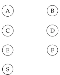
Figure1depicts an example network topology; the sink is placed at the ankle and other nodes are 120
placed over the body within the transmission range of sink. If nodes use the NoH criterion to choose 121
their parent, then all nodes should choose the sink. However if nodes use the RSSI criterion and all 122
nodes have the same transmission power, then nodes C and D should choose E or F as parent, and nodes 123
A B
C D
E F
S
Figure 1.Example topology where the sink S is at the ankle.
Secondly, it is desirable that parent nodes in the network tree are more or less equally loaded by 125
network traffic. This is because if a node is much more loaded than others, its energy will be depleted 126
prematurely, which well negatively affect the network’s lifetime. For nodes to be equally loaded by 127
traffic, the number of children should not vary greatly from one parent node to another, since parent 128
nodes forward traffic received from their children. The original protocol does not attempt to provide an 129
even distribution of child nodes to parent nodes. 130
Thirdly, the original protocol states that a child node should send aLeavemessage to its parent, 131
whenever the energy level of parent drops below some threshold. However, it is not clear from the 132
protocol’s description how the child will know the value of the parent’s energy. This is emphasized by 133
the fact that network traffic is sent only in the upstream direction, from child to parent. In this situation, 134
the parent needs to broadcast information about its energy level, either periodically or only when the 135
energy level drops below the configured threshold. Then, child nodes will be able to send theLeave 136
message in ample time. This way parent nodes will consume valuable energy and create more network 137
traffic than needed for collecting sensor data. 138
Fourthly and finally, the original protocol does not account for the need to send data in the 139
downstream direction from sink to nodes. Whereas upstream traffic is needed for collecting data 140
from sensors, downstream messages are necessary to perform network management tasks such as 141
modifying a node’s configuration, or sending a command to a node. 142
2.3. Modified Design–First Version 143
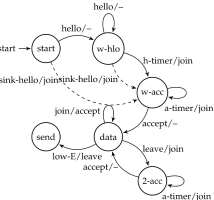
In a previous work [14], we presented Modified AMR (MAMR). Its finite state machine model is 144
depicted in Figure2. The initial sate is called “start”, and we have the following states: 145
• w-hlo: In this state, the node waits for “h-wait” time units to collectHellomessages, then it sends 146
aJoinmessage to one of theHellosenders and goes into state “w-acc”. 147
• w-acc: In this state, the node waits for anAcceptmessage for “a-wait” time units. If it receives an 148
Acceptmessage it switches to the “data” state, if not, it resends aJoinmessage. 149
• data: In this state, the node sends its own data to its parent and forwards data from its children. If 150
the node’s energy drops below a preset threshold (low-E event) it sends a broadcastLeavemessage 151
and goes into the “send” state. Also, in this state, the node is ready to receiveJoinmessages and 152
sendAcceptmessages. 153
• send: In this sate, the node only sends its own collected data. It does not forward data. 154
• 2-acc: The node goes into this state upon receiving aLeavemessage from its parent. This state is 155
similar to the “w-acc” state in that the node tries to join a parent to be able to re-enter the “data” 156
state. 157
The MAMR protocol is different than the original one in three aspects. The first is that we treat 158
theHellomessage received from sink no different than aHelloreceived from any other node. This 159
start
start w-hlo
w-acc
data send
2-acc hello/–
sink-hello/join
hello/–
h-timer/join
sink-hello/join
accept/–
a-timer/join join/accept
low-E/leave leave/join
a-timer/join accept/–
Figure 2.MAMR protocol’s Finite state machine.
(AMR). In AMR, once aHellomessage is received from sink, aJoinmessage is sent right away to sink 161
without continuing the “h-wait” time period. 162
The second modification is that we add a new metric that nodes use to choose their parent. This is 163
the Count of Children (CoC) metric. A node that uses this metric will choose as parent theHellosender 164
that has the least number of children. The objective is to make the number ofdirectchildren more or less 165
equal between parent nodes, so that the energy depletion rate is almost constant for all parent nodes. 166
The network lifetime is therefore increased by preventing early “death” (total depletion of energy) that 167
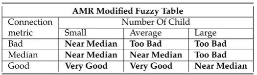
happens to overloaded nodes. Consequently, we modified the fuzzy logic function to include all metrics, 168
namely NoH, RSSI, BEL, and CoC. Table1is the original one from the AMR protocol, it has three inputs: 169
Number of hops, residual energy in node, and RSSI. The output is the connection metric. The design of 170
our fuzzy logic function is illustrated in Table2where the connection metric is an input along with the 171
number of children. The output of Table2is the one we use as the new fuzzy metric.
Table 1.Original Fuzzy Logic Control for AMR Protocol.
AMR Tradtional Fuzzy Table
Number Of Hops
Residual Energy
RSSI
Low Medium High
near Bad Bad Median Poor
near Bad Median Good Average
near Median Good Good Good
Medium Bad Bad Bad Poor
Medium Bad Median Median Average
Medium Median Median Good Good
Far Bad Bad Bad Poor
Far Bad Median Median Average
Far Median Median Median Good
172
Table 2.New Fuzzy Logic Control.
AMR Modified Fuzzy Table
Connection Number Of Child
metric Small Average Large
Bad Near Median Too Bad Too Bad
Median Near Median Near Median Too Bad
Good Very Good Very Good Near Median
parent from the list of senders. The MAMR protocol gives two options for the decision to send aLeave message. In MAMR-E, aLeavemessage is sent when the parent’s energy drops below a particular level. In MAMR-T, aLeavemessage is sent when the parent’stime till death tddrops below a particular value. The value oftdis estimated from the rate of decrease of energy:
td=Ecurr· ∆ t
∆E (1)
In Equation1above,Ecurris the current energy level, and∆tis the time it takes for energy to drop by a 173
value of∆E. 174
2.4. Modified Design–Second Version 175
Our second version of the protocol, presented hereafter, is called Two-way AMR (TAMR). We modify 176
MAMR to support bidirectional flow of data, i.e., upstream flow from nodes to sink and downstream 177
flow from sink to nodes. In MAMR, once the tree is constructed, each node will store only the address of 178
its parent in its routing table. This is sufficient for one-way (uni-directional) operation since all traffic 179
travels to the sink. Each node needs to know only what is the next tree node on the way to the sink. 180
When extending the MAMR protocol to design the TAMR protocol three issues need to be handled: 181
• The structure of the routing table in each node and how the table is filled and updated. 182
• The structure of protocol messages. 183
• The forwarding of data packets in the network tree. 184
The first modification to the MAMR protocol concerns routing tables. Now a routing table needs to 185
have two fields (columns): Final destination and next hop. In case of upward traffic, the final destination 186
is always the sink and the next hop is the node’s parent. So, upward traffic needs only a single entry in 187
the table. In case of downward traffic, the source is always the sink, but the final destination may be any 188
node in the network tree. As a result, there may be multiple routing table entries for downward traffic. 189
Due to the tree topology of the network, the routing table of a parent node will have only entries where 190
the destination is a descendant of this parent. Descendants of a parent are all the nodes of the subtree 191
rooted at this parent. The tree topology means that nodes that are not descendants of a parent cannot be 192
reached from this parent. So, the routing table in a node hasNd+1 entries, whereNdis the number of 193
descendants of this node and one more entry is needed for upward traffic. 194
In other words, a parent node needs to know which nodes are its descendants, and, for each 195
descendant, the parent needs to know the address of the next hop on the route to this descendant. In 196
order to convey this information to nodes, special routing packets could be used, but for WBANs, this 197
will consume precious energy, and possibly cause collisions with other packets. Hence, a degradation of 198
network performance may result. So, we decide to use data packets to convey this routing information by 199
modifying the packet structure. In the MAMR protocol, the packet contains only the source address since, 200
in upward traffic, the destination is always the sink. For TAMR, we add a field for the destination address. 201
We note here that this is a network layer header, so source and destination addresses are end-to-end, i.e., 202
they do not change as the packet travels from node to node. This is in contrast to addresses in the MAC 203
sender ID. Those are hop-by-hop addresses and change as the packet travels through the network. The 205
sender ID is address of the current sender of the packet not of the source of the packet. Also, the recipient 206
ID is the address of the current intended receiver of the packet not of the packet’s final destination. We 207
make use of this fact to fill the routing tables of nodes in a cross-layer fashion. 208
Sink 1A
1B
2A
3A
3B
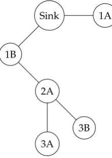
Figure 3.Example of a tree constructed by TAMR protocol.
When a node, e.g, node 3B in Figure3sends a data packet in the upward direction, i.e., to sink, it 209
knows from the tree construction phase that its parent is node 2A. Therefore, the header of the MAC 210
layer will have recipient ID = 2A and sender ID = 3B. The header of the network layer, however, will 211
have destination address = sink and source address = 3B. Of course, this implies that we are using MAC 212
addresses in the network layer which is a feature of a cross-layer approach. When the packet is received 213
by node 2A, it examines both headers of the MAC and network layers and can thus know the following 214
information: 215
• Node 3B is its descendant: This is known from the source address of the network layer header. 216
• Node 3B is its direct child: This is known from the sender ID of the MAC layer header. 217
Node 2A will then update its routing table by inserting an entry that indicates that Node 3B is the next 218
hop to node 3B, i.e., 3B is a dirsct child. In this step, in cross-layer interaction, a node reads information 219
from both the MAC header and network layer header to update its routing table. 220
Now node 2A forwards the packet by sending it to its parent; node 1B. The packet sent to 1B has 221
a MAC layer header with recipient ID = 1B and sender ID = 2A. The header of the network layer, will 222
have the same destination and source addresses as the packet sent by 3B, i.e., sink and 3B, respectively. 223
When node 1B receives the packet, it examines both headers of the MAC and network layers and can 224
thus know the following information: 225
• Node 3B is its descendant: This is known from the source address of the network layer header. 226
• Node 2A is its direct child and it is the next hop to node 3B: This is known from the sender ID of 227
the MAC layer header. 228
Node 1B updates its routing table accordingly, and finally, when the packet arrives at sink, the sink will 229
know that node 1B is the next hop to node 3B. We can thus conclude that a single upward-directed data 230
packet updates routing tables for all nodes on the route to sink. In other words, an entry is added to 231
these routing tables where the entry’s final destination is the source address of the packet (from the 232
network layer header) and the entry’s next hop is sender ID (from the MAC layer header). So, for the 233
routing table of a node to be fully updated, each of its descendants should send at least a single data 234
packet. The sink’s routing table will be fully updated when all nodes in the network have sent at least a 235
single data packet. 236
Similar to the MAMR protocol, the TAMR protocol gives two options for the decision to send a 237
level. In TAMR-T, aLeavemessage is sent when the parent’stime till death tddrops below a particular 239
value. The value oftdis estimated from1. 240
3. Analysis and Simulation 241
Network Simulator 2 (NS-2) was used to simulate the behavior of the original protocol (AMR), and 242
our two versions: MAMR and TAMR. Two scenarios are run where the network consists of a sink and 13 243
nodes. In the first scenario, the sink is placed at the ankle and in the second one, the sink is placed at the 244
waist. 245
3.1. Analysis of Operation 246
Ideally, all nodes should be able to join the network and send data. However, some factors affect 247
the operation of the protocol and may cause degradation in performance. Namely, these are: Collisions, 248
processing delays, values for timers, channel parameters, and number of retransmission retries. In 249
our simulation scenarios, we use the non-becon, no superframe CSMA/CA mode of operation of the 250
IEEE 802.15.6 protocol. A collision at the MAC layer causes retransmissions up to a particular number 251
of retries. Packet loss may therefore result. Also, a node takes some time to respond to an incoming 252
message. This processing delay may cause the some variation in network behavior. For instance, a node, 253
after joining the tree, broadcasts aHellomessage, after some delay. The variation in this delay between 254
different nodes affects the final topology of the tree, since some nodes may miss receiving theHello 255
message due to the expiration of their h-timer. This is also an example of how the values of timers (the 256
h-timer in this case) affect node behavior. Also, channel parameters are dynamic in WBANs and depend 257
on body posture. Communications may be disrupted, and path loss changes with time. Finally, due to 258
collisions and the limited number ofJoinretransmission retries, some nodes may not be able to join the 259
network. This happens when theJoinorAcceptmessages are lost or excessively delayed. 260
3.2. Simulation Results 261
In the first simulation scenario, the sink is located at the ankle of one leg, and the other 13 nodes are 262
placed the head (2 nodes), shoulders (2 nodes), arms (2 nodes each), waist (2 nodes), and legs (2 nodes at 263
one leg and one node at the other). In the second scenario, one of the waist nodes become sink and the 264
ankle sink becomes a regular node. 265
• Number of transmissions per delivered packet. 266
• Network lifetime, computed as the time that passes till the first node “death” in the network. Death 267
here means total energy depletion. We assume an initial energy of 2 Joules (J) [12]. 268
• Normalized residual energy averaged over all nodes. 269
Each parameter is computed for the protocol versions: AMR, MAMR-E, and TAMR-E. For each protocol 270
version, all parent choice metrics are used, namely, FLF, NoH, BEL, RSSI, and CoC. The CoC metric is the 271
one that we added in MAMR as explained in Section2.3. Figures4,5, and6present simulation results. 272
3.3. Results Discussion 273
• Network lifetime: In Figure4, we note that MAMR greatly improves network lifetime due to 274
the modified behavior of theLeavemessage. Also, TAMR provides a performance comparable 275
to MAMR. This is because TAMR does not use special routing packets but uses data packets to 276
deduce routing information. 277
• Residual energy: Figure5depicts the normalized residual energy averaged over all nodes, after 278
1000 sent data packets per node. We note that MAMR provides better performance by preventing 279
the situation where the energy of some network nodes are being sharply depleted. The dynamic 280
0 200 400 600 800 1000
FLF NoH BEL RSSI CoC Lifetime (Sink at Ankle)
AMR MAMR TAMR
0 200 400 600 800 1000
FLF NoH BEL RSSI CoC Lifetime (Sink at Waist)
AMR MAMR TAMR
Figure 4.Simulation Results for network lifetime.
0 10 20 30 40 50 60 70 80 90
FLF NoH BEL RSSI CoC Energy (Sink at Ankle)
AMR MAMR TAMR
0 10 20 30 40 50 60 70 80 90
FLF NoH BEL RSSI CoC Energy (Sink at Waist)
AMR MAMR TAMR
Figure 5.Simulation Results for normalized residual energy.
0 0.5 1 1.5 2
FLF NoH BEL RSSI CoC Tx per Packet (Sink at Ankle)
AMR MAMR TAMR
0 0.5 1 1.5 2
FLF NoH BEL RSSI CoC Tx per Packet (Sink at Waist)
AMR MAMR TAMR
nodes so that the energy depletion rate is almost even across all nodes. Again, TAMR provides 282
performance that is not significantly different than that of MAMR. 283
• Number of transmissions per delivered packet: Finally, In Figure6we show the average number 284
of transmissions per delivered packet for 1000 packets sent per node. Of course, when the sink is at 285
the ankle this number is larger than when the sink at the waist, since in general network end-to-end 286
paths will be longer. Also in MAMR the number is smaller. In fact, this shows a drawback in 287
MAMR, since, due to processing delays, a node may still send a packet or more to its parent even 288
after the parent has sent aLeavemessage. This type of packets will not be forwarded by the parent. 289
Here also we note that TAMR has comparable performance to MAMR. 290
4. Conclusion and Future Work 291
We presented a routing protocol for WBANs that enables communication in both upstream direction, 292
from nodes to sink, and downstream direction from sink to nodes. Most previous protocols in WBANs 293
focus on the upstream direction since it is the direction of data collected by sensors to be sent to a base 294
station or the cloud. This is the dominant direction in the network. However, we may need to send data 295
in the downstream direction to send configuration parameters or other commands to sensors. To this 296
end, our protocol enables a node in the network’s tree to store information about its children, in addition 297
to information about its parent. Simulation results show that the protocol leads to increased network 298
lifetime. We intend to extend the this work by investigating the performance of the protocol over the 299
IEEE 802.15.6 MAC and physical layer standard when using super frames with and without beacons. 300
301
1. Latré, B.; Braem, B.; Moerman, I.; Blondia, C.; Demeester, P. A Survey on Wireless Body Area Networks. 302
Wirel. Netw.2011,17, 1–18. 303
2. Movassaghi, S.; Abolhasan, M.; Lipman, J.; Smith, D.; Jamalipour, A. Wireless Body Area Networks: A 304
Survey. IEEE Communications Surveys & Tutorials2014,16. 305
3. Ullahn, S.; others. A Comprehensive Survey of Wireless Body Area Networks. Journal of Medical Systems 306
2012,36. 307
4. IEEE Computer Society. IEEE Std 802.15.6-2012 standard for local and metropolitan area networks part 15.6: 308
Wireless body area networks; IEEE Computer Society, 2012. 309
5. Rostampour, A.; Moghim, N.; Kaedi, M. A New Energy-Efficient Topology for Wireless Body Area Networks. 310
Journal of Medical Signals and Sensors2017,7. 311
6. Society, I.C.IEEE Std 802.15.4-2011, IEEE Standard for Local and metropolitan area networks—Part 15.4: Low-Rate 312
Wireless Personal Area Networks (LR-WPANs); IEEE Computer Society, 2011. 313
7. Deepak, K.; Babu, A. Improving energy efficiency of incremental relay based cooperative communications in 314
wireless body area networks.International Journal of Communication Systems2015,28, 91–111. 315
8. Cotton, S.L.; D’Errico, R.; Oestges, C. A review of radio channel models for body centric communications. 316
Radio Science2014. 317
9. Huq, M.A.; Iftikhar, M.; Chilamkurti, N. Behavior of IEEE 802.15.4 Channel Models on Implant Body Area 318
Network. Quality, Reliability, Security and Robustness in Heterogeneous Networks. Springer International 319
Publishing, 2017. 320
10. Bhanumathi, V.; Sangeetha, C.P. A guide for the selection of routing protocols in WBAN for healthcare 321
applications. Human Centric Computing and Information Sciences2017,7. 322
11. Bag, A.; Bassiouni, M.A. Hotspot Preventing Routing Algorithm for Delay-Sensitive Biomedical Sensor 323
Networks. 2007 IEEE International Conference on Portable Information Devices, 2007. 324
12. Ortiz, A.M.; Ababneh, N.; Timmons, N.; Morrison, J. Adaptive routing for multihop IEEE 802.15.6 Wireless 325
Body Area Networks. Proceedings of the 20th International Conference on Software, Telecommunications 326
and Computer Networks (SoftCOM), 2012. 327
14. Miky, A.; Saleh, M.; Mokhtar, B.; Rizk, M.R.M. Adaptive dynamic routing for IEEE 802.15.6 wireless body 329
area networks. 2018 35th National Radio Science Conference (NRSC), 2018. 330
c
2020 by the authors. Submitted toSensorsfor possible open access publication under the terms and conditions of 331