1 Ethiopia
3 Msc, Faculty of Electrical & Computer Engineering, Jimma Institute of Technology, Jimma, Ethiopia [email protected]
Abstract
In this paper, a capacitor microphone system is presented to improve the conversion of mechanical energy to electrical energy using a nonlinear auto regressive moving average-L2 (NARMA-L2) and model predictive control (MPC) controllers for the analysis of the open loop and closed loop system. The open loop system response shows that the output voltage signal need to be improved. The comparison of the closed loop system with the proposed controllers have been analyzed and a promising result have been obtained using Matlab/Simulink.
Keywords: Microphone, Nonlinear auto regressive moving average-L2, Model predictive control
1. Introduction
A capacitor microphone is a device which makes use of a capacitor to convert acoustical power into electric energy. Capacitor microphones require electricity from a battery or external supply. The ensuing audio signal is stronger signal than that from a dynamic. Capacitor microphone also have a tendency to be more sensitive and responsive than dynamics, making them properly-desirable to capturing subtle nuances in a sound. They are not best for excessive volume work, as their sensitivity makes them susceptible to distort. A capacitor has two plates with a voltage between them. In the capacitor mic, this sort of plates is product of very light fabric and acts as the diaphragm. The diaphragm vibrates when struck through sound waves, changing the space between the 2 plates and therefore changing the capacitance. Specifically, whilst the plates are nearer collectively, capacitance will increase and a charge current occurs. When the plates are in addition apart, capacitance decreases and a discharge current occurs. A voltage is required across the capacitor for this to paintings. This voltage is provided both by using a battery inside the mic or via external phantom power.
2. Mathematical Modeling of a Capacitor Microphone
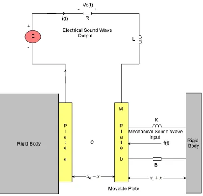
Figure 1 shows a system in which that takes place in a capacitor microphone. Plate a of the capacitor is attached to the rigid body. Sound waves impinge upon and exert a force on plate b of mass M, which is suspended from the rigid body by a spring K and which has damping B. The output voltage at the resistor R is intended to reproduce electrically the sound-wave patterns.
2
Figure 2 Capacitor microphone system
At equilibrium, with no external force extended on plate b, there is a charge q0 on the capacitor. This produces a force of attraction between the plates so that the spring is stretched by an amount x1 and the space between the plates is x0. When sound waves exert a force on plate b there will be a resulting motion x that is measured from the equilibrium position. The distance between the plates will then be x0-x, and the charge on the plates will be q0+q.
The capacitance is approximated by
00 0
1
A A
C and C
x x x
where is the dielectric constant for air and A is the area of the plate. We assume that the displacement ofx0 is big, so the circuit become open circuit and the initial current becomes zero.
The energy expressions for this system are
2 2
1 1
2
2 2
T Lq Mx
2 2
1 1
3
2 2
D Rq Bx
2
2
0 0 1
1 1
4
2 2
V x x q q K x x
A
The two degrees of freedom are the displacement x of plate b and the charge q on the capacitor. Applying Lagrange’s equation twice gives
2
0 1
1
5 2
Mx Bx q q K x x f t
A
3
With these approximations the system equations become
2 0 0 1 2 7 2 2q q q
Mx Kx Kx Bx f t
A A
0 0 0 0
8
x q q x x q
Lq Rq E
A A A
From Equation (7), by setting f (t)=0 and taking steady-state conditions, the result is
2 0 1 0 2 q Kx A
Similarly, in Equation (8) at equilibrium
0 0 0
0 x q q
E
A C
Therefore, the two system equations can be written in linearized form as
09
q
Mx Bx Kx q f t
A
0 0 0 10 q qLq Rq x
C A
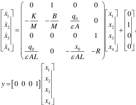
Let
1 , 2 , 3 , 4
x x x x v x q x q i and u f t
4
1 1 0 2 2 3 3 0 0 4 4 1 2 3 40 1 0 0
0 0
1
0 0 0 1 0
0 0
0 0 0 1
x K B q x
x M M A x
u x x q x x x R AL AL x x y x x
The system parameters are shown in Table 1 below
Table 1 System parameters
No Parameter Symbol Value
1 Mass of the Plate M 0.1 Kg
2 Spring stiffness K 0.5 N/m
3 Damping coefficient B 0.12 N-s/m
4 Area of the plate A 0.00005 m^2
5 Inductance of the circuit L 5 H
6 Resistance of the circuit R 23 ohm
7 Capacitance dielectric constant 8.85x10^-12 F/m
8 Initial charge q0 6.28x10^-15 C
9 Plates initial displacement x0 7x10^-4 m
The transfer function between the input force and the output charge become
4 3 11 2 11 12
24.2 3.164 10 3.797 10 1
2.838s
.582 10 11
s s
I s
F s s
G s
s
The output voltage at the resistor R is
12 RV s RI s
Substituting Equation (12) in to Equation (11) the transfer function between the input force and the output resistance voltage become
4 3 11 2 11 1224.2 3.164 10 3.797 10 1.582 10
65.3
R
s s s s
V s s
G s
F s
5
Figure 2 NARMA-L2 Controller.
Table 2 illustrates the network architecture, training data and training parameters of the proposed controllers.
Table 2 Neural network Parameters
3.2MPC Control
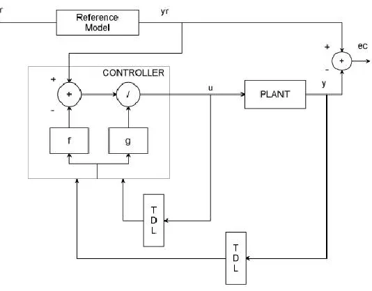
A block diagram of a model predictive control system is shown in Figure 3. A system model is used to count on the modern values of the output variables.
Network Architecture
Size of hidden layer 6 Delayed plant input 4
Sample interval(sec) 0.1 Delayed plant output 4 Training Data
Training sample 65 Maximum Plant output 2 Maximum Plant input 2 Minimum Plant output 1 Minimum Plant input 1 Max interval value (sec) 30
Min interval value (sec) 15 Training Parameters
6
Figure 3Block diagram for model predictive control.
The residuals, the variations a number of the actual and predicted outputs, function the comments sign to a Prediction block. The predictions are utilized in two styles of MPC calculations which might be achieved at each sampling right now: set-factor calculations and manage calculations. Inequality constraints at the input and output variables, consisting of better and decrease limits, can be included in both type of calculation.
4. Result and Discussion
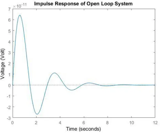
4.1Open Loop Response of the Capacitor Microphone System
The response of the open loop capacitor microphone for a 0.01 N impulse response is shown in Figure 4 below.
Figure 4 Open loop response
7
Figure 5 Simulink model of the capacitor microphone system with NARMA-L2 and MPC controllers for a step desired sound waves voltage input signal
The simulation result is shown in Figure 6.
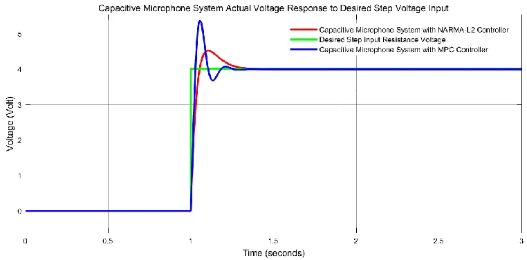
Figure 6 Step response simulation result
The data of the rise time, percentage overshoot, settling time and peak value is shown in Table 3.
Table 3 Step response data
No Performance Data NARMA-L2 MPC
1 Rise time 1.08 sec 1.08 sec
2 Per. overshoot 12.5 % 32.5 %
3 Settling time 1.38 sec 1.38 sec
8
As Table 3 shows that the capacitor microphone system with NARMA-L2 controller improves the performance of the system by minimizing the percentage overshoot.
4.3Comparison of the Capacitor Microphone System with NARMA-L2 and MPC Controllers for a Random Desired Sound Waves Voltage Input
The Simulink model of the capacitor microphone system with NARMA-L2 and MPC controllers for a random desired sound waves voltage input signal is shown in Figure 7 below.
Figure 7 Simulink model of the capacitor microphone system with NARMA-L2 and MPC controllers for a random desired sound waves voltage input signal
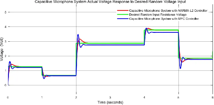
The simulation result is shown in Figure 8.
Figure 8 Random response simulation result
The simulation result shows that the capacitor microphone system with NARMA-L2 controller improves the performance of the system by minimizing the percentage overshoot with an exact steady state value while the capacitor microphone system with MPC controller losses its performance in tracking the steady state value after 2 second.
9
the capacitor microphone system with NARMA-L2 controller improves the performance of the system by minimizing the percentage overshoot with an exact steady state value while the capacitor microphone system with MPC controller losses its performance in tracking the steady state value after 2 second. Finally, the comparative simulation proved that the capacitor microphone system with NARMA-L2 controller improved the performance of the system.
Reference
[1].Sedighe B. S et al. “Design and Modeling of a Highly Sensitive Microelectromechanical System Capacitive Microphone” J. of Micro/Nanolithography, MEMS, and MOEMS, Vol. 19, No. 2, 2020.
[2].Lars U. et al. “A High Quality Digital Radio Frequency Capacitor Microphone with Improved Dynamic Range” The Journal of the Acoustical Society of America, Vol. 147, No. 1953, 2020.
[3].M. Ali Shah et al. “Design Approaches of MEMS Microphones for Enhanced Performance” Journal of Sensors, Vol. 2019, Article ID 9294528, 26 pages, 2019.
[4].Germano N. et al. “MEMS Capacitive Microphones: Acoustical, Electrical and Hidden Thermal-Related Issues” IEEE Sensors Journal, Vol. 18, Issue 13, 2018.
[5].Takanori U. et al. “System Identification of Velocity Mechanomyogram Measured with a Capacitor Microphone for Muscle Stiffness Estimation” Journal of Electromyography and Kinesiology, Vol. 33, pp. 57-63, 2017.
[6].Shakiba Dowlati et al. “An Accurate Study on Capacitive Microphone with Circular Diaphragm using a Higher Order Elasticity Theory” Latin American Journal of Solids and Structures, Vol. 13, Issue 4, pp. 590-609, 2016.