Analysis of Composite Column Building with
Lateral Load Resisting Systems using Etabs
R.Aparna Shetty 1, R.Master Praveen Kumar 2
P.G. Student, Department of Civil Engineering, Brindavan Institute of Technology & Science, Chinnatekur, Andhra
Pradesh, India1
Assistant Professor, Department of Civil Engineering, Brindavan Institute of Technology & Science, Chinnatekur,
Andhra Pradesh, India2
ABSTRACT: The present work seeksto researchtheseismicbehavior of a high rise building with composite columns and building with shear walls & composite column and also with bracings and composite column, building with composite column, bracings, shear walls are examine the keystyleproblems involved.The currentstudy deals withunstablebehavior of multi storiedframedstructure assessed through equivalent statictechniqueof studyas per IS: 1893-2002 for zone III & zone V in three soils (soil-I soil-II soil-III) by using ETABS software (2016 version). The analysesperformed ona collectionof twoforms ofstandardmoment resistingframed3Darea models withtotally compositecolumns. The analysis isprovidedand therefore theresultscompared in terms ofimportantearthquake response parameterslikeBase shear,storey displacements and lateral forces on building elevation.
KEYWORDS:Lateral Load resisting systems, Different types of Soils, Earthquake Zones, ETABS
I. INTRODUCTION
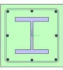
Composite columns are constructed using various combinations of structural steel and concrete in an attempt to utilize the beneficial properties of each material. The interactive and integral behavior of concrete and the structural steel elements makes the composite column a very stiff, more ductile, cost effective and consequently a structurally efficient member in building and bridge constructions.
Mainly three types of composite column sections are used in high-rise building construction.
Fig 1.1 Showing Typical view of Composite column
progress in numerical studies are comparatively less. Recently, a nonlinear finite element models investigating the behavior of concentric and eccentric axial load of FEC columns was developed by different researchers. The design of composite columns has been addressed by a large number of design specifications.
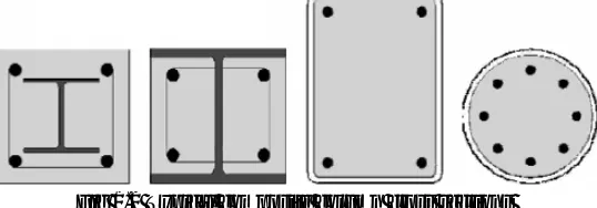
Composite columns may take a range of forms, as shown in the figure below. As with all composite elements they are attractive because they play to the relative strengths of both steel and concrete. This can result in a high resistance for a relatively small cross sectional area, thereby maximising useable floor space. They also exhibit particularly good performance in fire conditions.
Fig 1.2 Typical composite column cross sections
Design rules for composite columns in structural frames are given in BS EN 1994-1-1[4]. This is the first time that guidance has been given in a code for use in the UK, which may explain why composite columns have been rarely used to date. Rules are provided for composite H sections, either fully or 'partially encased' (web infill only), and for concrete filled hollow sections. Typical cross sections are shown. Composite columns requiring formwork during execution tend not to be viewed as cost-effective in the UK.
Concrete filled hollow section compression members need no formwork and they use material more efficiently than an equivalent H section. Concrete infill adds significantly to the compression resistance of the bare steel section by sharing the load and preventing the steel from buckling locally. The gain in fire resistance may be at least as valuable, especially if it permits the column to be left unprotected or only lightly protected. Infill concrete retains free water which in other situations would be lost; its latent heat of evaporation significantly delays temperature rise.
Rectangular and circular hollow sections can be used. Rectangular sections have the advantage of flat faces for end plate beam-to-column connections (using Flow drill or Hollow connections). Ordinary fin plates can be employed with either shape.
A programmed, Fire Soft, for the design of concrete filled hollow sections in ambient and fire conditions has been developed.
Composite construction:
Composite construction dominates the non-residential multi-storey building sector. This has been the case for over twenty years. Its success is due to the strength and stiffness that can be achieved, with minimum use of materials.
Benefits of Composite Construction
1. The benefits of composite construction include speed of construction, performance and value. Steel framing
for a structure can be erected quickly and the pre-fabricated steel floor decks can be put in place immediately.
When cured, the concrete provides additional stiffness to the structure.
2. Additionally, the concrete encasement protects the steel from buckling, corrosion and fire. Service integration
within the channels on the composite decks is another advantage to composite construction.
3. Building quality standards can be adhered to easily by the use of pre-fabricated decks. Excessive deflections
can be controlled by cambering the beams or by shoring the metal decks to limit deflection when concrete is
poured.
Advantages Of Steel-Concrete Composite Construction
1. Most effective utilization of materials viz. concrete in compression and steel in tension.
2. High ductility of steel leads to better seismic resistance of the composite section. Steel component can be
deformed in a ductile manner without premature failure and can withstand numerous loading cycles before
fracture.
3. Steel component has the ability to absorb the energy released due to seismic forces through its unique property
called ductility.
4. Ability to cover large column free area. This leads to more usable space. Area occupied by the composite
column is less than the area occupied by the RCC column
5. Faster construction by utilizing rolled and/or pre-fabricated components. Also speedy construction facilitates
quicker return on the invested capital.
6. Quality of steel is assured since it is produced under controlled environment in the factory under strict Quality
Assurance Plan (QAP). More use of steel in composite construction compared to that in RCC structure ensures
better quality control.
7. Cost effective, based on life cycle cost analysis since steel structures can be maintained easily and less
frequent repairs are required for steel structure.
8. Steel is more durable, highly recyclable and hence environment friendly.
9. Keeping span/loading unaltered, smaller structural sections are required compared to non-composite
construction. Therefore, reduction in overall weight of the composite structure compared to the RCC
construction results lesser foundation costs.
10. Cost of formwork is lower compared to RCC construction.
11. Cost of handling and transportation is less because major part of structure is fabricated in workshop near the
12. The steel component and hence the steel-concrete composite construction is more resistant against accidental
loads compared to RCC construction
13. Composite sections have higher stiffness compared to only steel construction and hence experience lesser
deflection than the non-composite steel sections.
Shear wall structures:
Adequate stiffness is to be ensured in high rise buildings for resistance to lateral loads induced by wind or seismic events. Reinforced concrete shear walls are designed for buildings located in seismic areas, because of their high bearing capacity, high ductility and rigidity. In high rise buildings, beam and column sizes work out large and reinforcement at the beam-column junctions are quite heavy, so that, there is a lot of clogging at these joints and it is difficult to place and vibrate concrete at these places which does not contribute to the safety of buildings. These practical difficulties call for introduction of shear walls in High rise buildings.
Concrete or masonry continuous vertical walls may serve both architecturally as partitions and structurally to carry gravity and lateral loading. There will be no architectural difficulty in extending them through the height of the building; their very high in plane stiffness and strength had proved them to be ideally suited for resisting lateral loads. Compared to frame type structures, shear-wall structures offer less distortion and less damage to nonstructural elements. Care shall be taken to have symmetrical configuration of walls in the building so that torsion effect in plan could be avoided.
In a shear wall structure, shear walls are entirely responsible for the lateral load resistance of the building due to seismic and wind loadings. These shear walls act as vertical cantilevers in the form of separate planar walls, and also as non planar assemblies of connected walls around stair case, elevators and service shafts. Shear walls are much stiffer horizontally than rigid frames. Shear walls are much economical up to about 35 stories. In contrast to the rigid frames, the shear walls’ solid form tends to restrict open internal spaces where required. However, they are well suited to hotels and residential buildings where the floor by floor repetitive planning allows the shear walls to be vertically continuous. They also serve excellent acoustic and fire insulators between rooms and apartments.
Use of bracing system in decreasing the effective length of the column
A new bracing system shaped like a diamond is incorporated in the main building frame and its applicability is evaluated by detailed calculations. It is also compared with the other known bracing system known as the cross bracing system. Both the bracing system has been shown below.
Fig-1.1 Showing different types of bracings
design demands, often denoted by target displacement, on the existing structural and non-structural components, are less than their capacities (Figure 1). Lower demands may reduce the risk of brittle failures in the structure and/or avoid the interruption of its functionality. The attainment of global structural ductility is achieved within the design capacity by forcing inelasticity to occur within dissipative zones and ensuring that all other members and connections behave linearly.
Bracing may be inefficient if the braces are not adequately capacity-designed. Braces can be aesthetically unpleasant where they change the original architectural features of the building. In addition, braces transmit very high actions to connections and foundations and these frequently need to be strengthened.
III.NUMERICALMODELLING Building dimensions
The building is 24m x 24m in plan with columns spaced at 6m from center to center. A floor to floor height of
3.0m is assumed. The location of the building is assumed to be at zone-5 & soil-3.
Column size : 500mm X 650 mm
Beam size : 400mm X 450 mm
Shearwall Thickness 230 mm
Bracing size: 230mmx230mm,
Slab thickness: 120mm,
Live load: 3KN
Floor Finish: 1KN
Mix proportion: M30
Grade of steel :Fe 500
Load Combination: (DL+LL+EQX+WIND X) 1.2
Dead load - 1.2
Live load - 1.2
EQX - 1.2
Windward Coefficient : 0.8
Leeward coefficient : 0.5
5.5 Load Cases 5.5.1. Live Load
Live load is assumed as per IS 875(part 2-imposed loads) table 1. the building is analysed by assuming it to be a
residential building the live load was taken as 2KN/m2
5.5.2. Earth Quake Load
Earth Quake load in this analysis is accordance to IS 1893(part 1)-2002. The buildings models are prepared in all seismic zones i.e. in Z2, Z3, Z4 and Z5. Therefore the value of Z is taken as 0.1, 0.16, 0.24 and 0.36 respectively. And
the models are made in all types of soils i.e., Hard/ Rocky (Type I), Medium soil (Type II) and in Loose soil (Type III).
5.5.3. Load combinations:
As per clause 6.3.1.2 of IS 1893 different load combinations are
Static & dynamic Loading:
1.5(Dead load + Live load)
1.2(Dead load + Live load + Lateral load in X direction)
1.2(Dead load + Live load - Lateral load in X direction)
1.2(Dead load + Live load + Lateral load in Y direction)
1.2(Dead load + Live load - Lateral load in Y direction)
1.5(Dead load + Lateral load in X direction)
1.5(Dead load - Lateral load in X direction)
1.5(Dead load + Lateral load in Y direction)
1.5(Dead load - Lateral load in Y direction)
0.9(Dead load) + 1.5(Lateral load in X direction)
0.9(Dead load) - 1.5(Lateral load in X direction)
0.9(Dead load) + 1.5(Lateral load in Y direction)
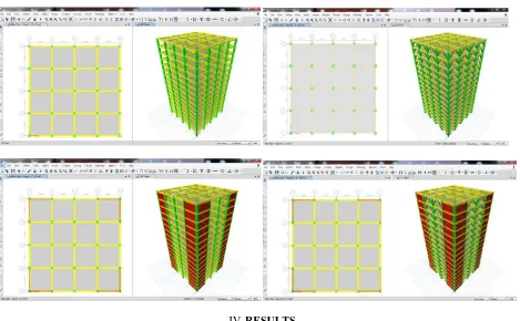
IV.RESULTS
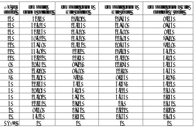
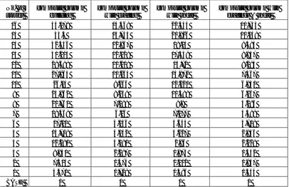
Table : 1 Comparative values of Displacement in Zone-3 Soil-1 in Linear Static Analysis.
No. of stories
composite column building
composite column with bracing
composite column with shear
composite column with bracings & shear 16 25.26 10.737 16.655 7.98 15 24.746 10.186 15.431 7.52 14 24.034 9.605 14.186 7.102 13 23.115 8.985 12.926 6.636 12 21.999 8.319 11.645 6.137 11 20.714 7.612 10.35 5.616 10 19.289 6.873 9.054 5.073 9 17.75 6.113 7.778 4.509 8 16.12 5.343 6.53 3.932 7 14.422 4.574 5.329 3.351 6 12.675 3.816 4.195 2.774 5 10.896 3.08 3.147 2.211 4 9.097 2.377 2.21 1.674 3 7.283 1.715 1.406 1.174 2 5.419 1.106 0.762 0.726 1 3.317 0.552 0.306 0.353
Graph : 1 Displacement variation along Zone-3 soil-1 in Linear Static Analysis
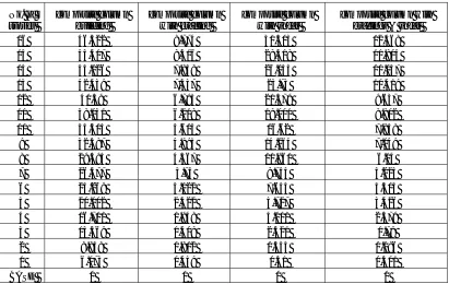
Table : 2 Comparative values of Displacement in Zone-3 Soil-2 in Linear Static Analysis.
No. of stories
composite column building
composite column with bracing
composite column with shear
composite column with bracings & shear
16 34.33 14.576 22.619 9.265
15 33.648 13.846 20.98 8.746
14 32.686 13.063 19.292 8.26
13 31.436 12.219 17.578 7.719
12 29.918 11.302 15.836 7.139
11 28.171 10.34 14.075 6.526
10 26.233 9.334 12.312 5.893
9 24.139 8.3 10.566 5.236
8 21.922 7.252 8.865 4.564
7 19.613 6.205 7.229 3.887
6 17.237 5.174 5.684 3.214
5 14.817 4.173 4.258 2.559
4 12.371 3.215 2.981 1.933
3 9.904 2.314 1.886 1.351
2 7.369 1.485 1.009 0.829
1 4.504 0.733 0.388 0.395
BASE 0 0 0 0
0 5 10 15 20 25 30
d
is
p
la
ce
m
e
n
t
no of stories
Displacement Vs Stories in zone3-soil-1 in Linear
Static Analysis
composite column building
composite column with bracing
composite column with shear
Graph : 2 Displacement variation along Zone-3 soil-2 in Linear Static Analysis
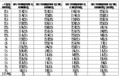
Table : 3 Comparative values of Displacement in Zone-3 Soil-3 in Linear Static Analysis.
No. of stories
composite column building
composite column with bracing
composite column with shear
composite column with bracings & shear
16 42.14 17.081 27.755 9.265
15 41.313 16.235 25.759 8.746
14 40.136 15.319 23.688 8.26
13 38.602 14.329 21.585 7.719
12 36.738 13.252 19.446 7.139
11 34.592 12.12 17.283 6.526
10 32.212 10.94 15.118 5.893
9 29.641 9.727 12.974 5.236
8 26.919 8.498 10.88 4.564
7 24.083 7.27 8.866 3.887
6 21.165 6.06 6.967 3.214
5 18.194 4.885 5.215 2.559
4 15.191 3.761 3.645 1.933
3 12.161 2.704 2.3 1.351
2 9.049 1.732 1.221 0.829
1 5.526 0.851 0.466 0.395
BASE 0 0 0 0
0 5 10 15 20 25 30 35 40
16 14 12 10 8 6 4 2 BASE
d
is
p
la
ce
m
e
n
t
no. of stories
Displacement Vs Stories in zone3-soil-2 in Linear
Static Analysis
composite column building
composite column with bracing
composite column with shear
Graph : 3 Displacement variation along Zone-3 soil-3 in Linear Static Analysis
Table : 4 Comparative values of Displacement in Zone-5 Soil-1 in Linear Static Analysis.
No. of stories
composite column building
composite column with bracing
composite column with shear
composite column with bracings & shear
16 34.078 14.469 22.454 10.733
15 33.4 13.745 20.826 10.148
14 32.446 12.967 19.15 9.584
13 31.205 12.129 17.449 8.957
12 29.698 11.219 15.72 8.284
11 27.964 10.264 13.972 7.567
10 26.04 9.266 12.221 6.831
9 23.962 8.239 10.488 6.067
8 21.761 7.199 8.8 5.286
7 19.469 6.16 7.177 4.499
6 17.11 5.136 5.643 3.718
5 14.708 4.142 4.227 2.956
4 12.281 3.191 2.96 2.229
3 9.831 2.297 1.873 1.552
2 7.315 1.474 1.002 0.947
1 4.471 0.728 0.386 0.444
BASE 0 0 0 0
0 5 10 15 20 25 30 35 40 45
d
is
p
la
ce
m
e
n
t
no. of stories
Displacement Vs Stories in zone3-soil-2 in Linear Static
Analysis
composite column building
composite column with bracing
composite column with shear
Graph : 4 Displacement variation along Zone-5 soil-1 in Linear Static Analysis
Table : 5 Comparative values of Displacement in Zone-5 Soil-2 in Linear Static Analysis.
No. of stories
composite column building
composite column with bracing
composite column with shear
composite column with bracings & shear
16 46.322 8.774 30.505 12.468
15 45.417 8.316 28.318 11.804
14 44.126 7.838 26.043 11.147
13 42.439 7.337 23.73 10.419
12 40.39 6.795 21.379 9.637
11 38.031 6.218 19.001 8.802
10 35.414 5.615 16.62 7.938
9 32.587 4.995 14.264 7.049
8 29.595 4.367 11.961 6.14
7 26.477 3.74 9.744 5.223
6 23.269 3.122 7.654 4.313
5 20.002 2.522 5.727 3.426
4 16.701 1.948 4.001 2.579
3 13.369 1.409 2.521 1.79
2 9.948 0.912 1.335 1.086
1 6.073 0.459 0.51 0.501
BASE 0 0 0 0
0 5 10 15 20 25 30 35 40
d
is
p
la
ce
m
e
n
t
no. of stories
Displacement Vs Stories in zone5-soil-1 in Linear
Static Analysis
composite column building
composite column with bracing
composite column with shear
Graph : 5 Displacement variation along Zone-5 soil-2 in Linear Static Analysis.
Table : 6 Comparative values of Displacement in Zone-5 Soil-3 in Linear Static Analysis.
No. of stories
composite column building
composite column with bracing
composite column with shear
composite column with bracings & shear
16 56.866 23.034 37.437 12.468
15 55.765 21.91 34.769 11.804
14 54.183 20.681 31.978 11.147
13 52.112 19.343 29.139 10.419
12 49.596 17.889 26.252 9.637
11 46.699 16.349 23.332 8.802
10 43.486 14.756 20.408 7.938
9 40.015 13.117 17.515 7.049
8 36.34 11.457 14.687 6.14
7 32.512 9.799 11.965 5.223
6 28.572 8.165 9.394 4.313
5 24.561 6.578 7.022 3.426
4 20.507 5.06 4.898 2.579
3 16.416 3.633 3.079 1.79
2 12.216 2.319 1.622 1.086
1 7.453 1.133 0.62 0.501
BASE 0 0 0 0
0 5 10 15 20 25 30 35 40 45 50 1
6 15 14 13 12 11 10 9 8 7 6 5 4 3 2 1
B A SE d is p la ce m e n t
no. of stories
Displacement Vs Stories in zone5-soil-2 in Linear
Static Analysis
composite column building
composite column with bracing
composite column with shear
Graph : 6 Displacement variation along Zone-5 soil-3 in Linear Static Analysis.
V. CONCLUSION
1. Analysis carried out on two different heights of buildings i.e.. 45m in both static analysis and dynamic
analysis with composite column and shear wall at optimum locations.
2. From the analysis Displacement is compared for all the models in zone 3 & zone 5 and it can be concluded
that displacement is increasing with increase in height and the displacement can be reduced by providing shear
walls at optimum locations.
3. When Displacement is analysed in linear static analysis it is observed that 40% of displacement is reduced
when shear walls are provided at optimum locations.
REFERENCES
1. IS: 456-code of practice for plain and reinforced concrete.
2. IS: 875(part 1-5) - code of practice for structural safety of Building loading standards. 3. IS 1893(Part-1):2002, Criteria for earthquake resistant design of structures.
4. IS 13920:1993, Ductile detailing of reinforced concrete structure subjected to seismic forces-code of practice. 5. SP: 16-design aids for reinforced concrete.
6. Earthquake resistant design by pankaj agarwal.
7. Rosinblueth and Holtz “Analysis of shear walls in tall buildings” (1960).
8. Clough.R, King I.P and Wilson E.I-“Structural analysis of multi storied buildings” (1964).
9. Khan, F.R. and Sbrounis, J.A, (7) „Introduction of shear wall with frames in concrete Sabrcounis structure under lateral loads (1964). 10. Agarwal P. and M Shrikhande (2007), “Earthquake Resistant Design of Structures”, Prentice Hall of India Pvt. Ltd., 2007, New Delhi. 11. Stefano, M.D., and Pintucchi, B., june 2-5,2002, “A Model For Analyzing Inelastic Seismic Response Of Plan-Irregular Buiding Structures”,
15th ASCE engineering mechanics conference, Columbia University, New York, NY
12. Aoyama, H.,2001, Design of Modern High Rise Reinforced Concrete Structures,Imperial College Press, London, UK.
0 10 20 30 40 50 60
d
is
p
la
ce
m
en
t
no. of stories
Displacement Vs Stories in zone5-soil-3 in Linear
Static Analysis
composite column building
composite column with bracing
composite column with shear