Design Optimization of Sports Utility Vehicle
Chassis
Dileep Krishnadas K
1, Dr.S.Sankar
2, Tedy Thomas
3, Deepak.V.K
4PG Student, Dept. of Mechanical Engineering, Nehru College Of Engineering and Research Centre, Thrissur, Kerala,India1
HOD, Dept. of Mechanical Engineering, Nehru college of engineering and Research Centre,Thrissur,Kerala,India2
Assistant Professor, Dept. of Mechanical Engineering, Nehru college of engineering and Research Centre, Thrissur, Kerala, India3
Assistant Professor, Dept. of Mechanical Engineering, Nehru college of engineering and Research Centre, Thrissur, Kerala, India4
ABSTRACT: The vehicle chassis frame is an important part of an automobile. The chassis frame is the main structure of any vehicle. In this project work chassis for a SUV was designed using SolidWorks 2016 edition and analysed using Ansys R15.0. Chassis with side members having three different cross sections such as rectangular, square and circular were analysed by applying the working load and the results were compared to select the chassis with least total deformation. Then the selected chassis was modified and was subjected to a shear force and was analysed. Then the results were compared with analysis results of the initially designed chassis. Then the chassis with least value of total deformation was selected and was applied with three different materials and the results were compared to select the most suitable material. Then the chassis model with the least value of total deformation applied with the most suitable material was analysed and results were evaluated. Then modal analysis of the optimized chassis applied with the most suitable material was performed. The analysis data was used to perform the harmonic response analysis of the chassis and different properties of the chassis were analysed. From the results it can be concluded that chassis with rectangular cross section applied with ASTM A302 alloy steel is the best choice for sports utility vehicle.
KEYWORDS: Chassis, Crossmembers, ASTM A70 steel, Carbon steel AISI 4130,ASTM A302 alloy steel.
I. INTRODUCTION
warping when simple, perpendicular cross members are used. The main advantages are that they are cheap to hand build and can cope with heavy loads. The major drawback is that it has low torsional rigidity, because it is a two dimensional chassis.
II. DESIGNPROCEDURE
This section deals with the process of modeling. Model is a representation of an object, a system, or an idea in some form other than that of the entity itself. Modeling is the process of producing a model; a model is a representation of the construction and working of some system of interest. A model is similar to but simpler than the system it represents. Generally, a model intended for a simulation study is a mathematical model developed withthe help of simulation software. Softwares commonly used for modelling are SolidWorks, Creo, Catia, Unigraphics etc. In this project SolidWorks 2016 edition is used for the modelling process.
Design of vehicle chassis
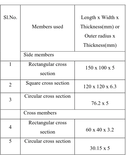
Table 1 Dimensions of vehicle chassis
Fig.1 Chassis frame Table 2 Dimensions of cross members in chassis
Fig.2 Chassis model designed using SolidWorks 2016
S.no Description Dimensions(mm)
1 Length 4000
2 Width 1390
3 Front overhang 741.35
4 Rear overhang 630.54
5 Wheel base 2628.11
Sl.No.
Members used
Length x Width x
Thickness(mm) or
Outer radius x
Thickness(mm)
Side members
1 Rectangular cross
section
150 x 100 x 5
2 Square cross section 120 x 120 x 6.3
3 Circular cross section
76.2 x 5
Cross members
4 Rectangular cross
section 60 x 40 x 3.2
5 Circular cross section
III. ANSYSPROCEDURE
This section deals with the analysis of the designed model. The model that is in STEP format is analysed. Static structural analysis of both stabilizer bar link and suspension system is performed by applying the working load and number of supports used is two. The model is imported to Ansys and meshing is performed. The mesh size used is 4.4 mm. From the results obtained optimal design is selected. Suitable materials are applied to three different models of stabilizer bar link and modal analysis is performed. Different softwares such as Comsol, Radioss solver, Abaqus, Hypermesh, Ansys etc. are used for analysis. In this project Ansys R15.0 is used for design analysis.
Design Analysis
The figure shown below represents the meshed image and force application in vehicle chassis.
Fig.3 Meshed image of vehicle chassis Fig.4 Force application in vehicle chassis
The figure shown below represents the total deformation of vehicle chassis with rectangular cross section side members
Table 3 Overview of analysis results
Fig.5.Total deformation of chassis with rectangular cross section side members
Sl.No
Side member crosssection
Maximum total deformation
(mm)
1
Rectangular 0.176382
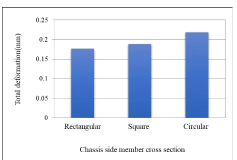
Square 0.18879From the analysis results it can be concluded that the chassis with rectangular cross section members have the least value of maximum total deformation. Hence chassis with rectangular cross section members is selected for further analyses.
The figure shown below represents the total deformation of modified design of chassis with rectangular cross section members
Table 4 Overview of analysis results
Fig.6 Total deformation of modified design of chassis with rectangular cross section members
From the analysis results it can be concluded that themodified design of chassis with rectangular cross section members have the least value of maximum total deformation. Hence the modified design of chassis with rectangular cross section members is selected as the best suitable system.
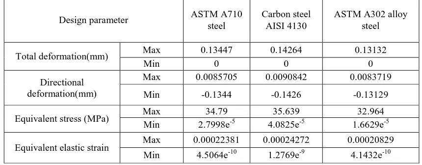
IV.MATERIAL OPTIMISATION
The above shown table represents analysis results of the chassis using three different materials.Three different materials are applied to the vehicle chassis and the analysis results are compared to select the most suitablematerial. The three different materials used for analyses are ASTM A710 steel,Carbon steel AISI 4130 and ASTM A302 alloy steel.
Table 5 Overview of analysis results of the chassis using three different materials
Design parameter ASTM A710
steel
Carbon steel AISI 4130
ASTM A302 alloy steel
Total deformation(mm) Max 0.13447 0.14264 0.13132
Min 0 0 0
Directional deformation(mm)
Max 0.0085705 0.0090842 0.0083719
Min -0.1344 -0.1426 -0.13129
Equivalent stress (MPa) Max 34.79 35.639 32.964
Min 2.7998e-5 4.0825e-5 1.6629e-5
Equivalent elastic strain Max 0.00022381 0.00024272 0.00020829
Min 4.5064e-10 1.2769e-9 4.1432e-10
Sl.No Chassis subjected to
analysis
Maximum total deformation (mm)
1 Initially designed
chassis 0.12358
V. MODALANALYSISANDHARMONICRESPONSEANALYSIS
Modal analysis Harmonic response analysis
Table 6 Total deformation of chassis at Table 7 Overview of harmonic response analysis results differentnatural frequencies
From Table 6 it can be concluded that the natural frequency at which the total deformation value is minimum is the first modal frequency. The first modal frequency value is 62.292 Hz and the total deformation value at this particular frequency value is 3.2032 mm. The results obtained from modal analysis are used to perform the harmonic response analysis of the chassis.
VI RESULTS AND DISCUSSION
Fig. 7 Total deformation of chassis vs chassis side member cross section
Chassis with side members having rectangular cross section was modified by increasing thickness of the cross section from 5 mm to 6.3 mm. Then both the initially designed and modified chassis was subjected to analysis by applying a
Sl.No. Design parameter Max Min
1 Total deformation
(mm) 831.43 0
2 Directional
deformation (mm) 21.078 -25.711
3 Equivalent elastic
strain 0.29812 7.545e
-14
4 Equivalent stress
(MPa) 62116 1.1851e
-9
5 Elastic strain
intensity 0.45303
8.5948e
-15
6 Normal stress
(MPa) 45658 -41803
7 Normal elastic
strain 0.12962 -0.12855
Mode Frequency(Hz) Total deformation (mm)
Max Min
1 62.292 3.2032 0
2 75.713 9.2614 0
3 82.771 9.0721 0
4 84.686 6.7197 0
5 86.338 9.469 0
shear force of value 10000 N in opposite directions on both side mebers. It was found out that the total deformation of the modified chassis has reduced by 26.06%. The design modification of the chassis has increased the weight of the chassis from 357.47kg to 393.92 kg. Hence the weight of the modified chassis is increased by 36.45 kg
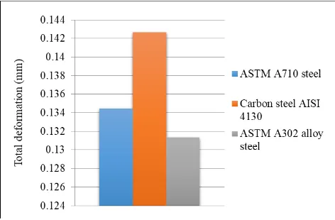
Fig 8 Comparison of total deformations of chassis applied with three different materials
The three different materials such as ASTM A710 steel, Carbon steel AISI 4130 and ASTM A302 alloy steel were applied to the chassis and it was found out that the chassis applied with ASTM A302 alloy steel exhibits the minimum total deformation.
VII.CONCLUSION
In this project a chassis for a SUV was designed using SolidWorks 2016 edition and the designed model was analysed using ANSYS R15.0. Initially three chassis with different side member cross sections were designed. Then a force equivalent to the load acting on the chassis of value 19122.97 N was applied. From the analysis results it was found out that chassis with side members having rectangular cross section has minimum total deformation. Then the chassis was modified by increasing the thickness of side member cross section from 5 mm to 6.3 mm. The weight of chassis was then increased by 36.45 kg. Total deformation of the modified and initially designed chassis were analysed by applying a shear force of 10000 N in opposite directions acting along X axis and it was found out from the analysis results that modified chassis has better resistance to shear forces by 26.06% as compared to the initially designed chassis. Then three different materials such as ASTM A710 steel, Carbon steel AISI 4130 and ASTM A302 alloy steel were applied and the total deformation values under a load of value 19122.97 N were calculated and it was found out that chassis applied with ASTM A302 alloy steel has the minimum total deformation. Thus ASTM A302 alloy steel was selected as the chassis material and the modal analysis of the chassis was carried out. The first six natural frequencies of the chassis was found out. Also the total deformation values at these six natural frequencies were found out. The analysis data obtained from modal analysis was used to perform harmonic response analysis and different design parameters such as total deformation, directional deformation, equivalent elastic strain, equivalent stress, normal stress and normal elastic strain were evaluated and the results were tabulated.
REFERENCES
[1] Dave Anderson and Grey Schede, “Development of a Multi- Body Dynamic Modal of Tractor – Semi trailer for
[2] I.M. Ibrahim, D.A.Crolla and D.C. Barton, “Effect of Frame Flexibility on the Ride Vibration of Trucks”, Department of Mechanical Engineering, University of Leeds LS2 9JT, U.K. August 1994
[3] Murali M.R. Krisna, “Chassis Cross-Member Design Using Shape Optimization”, International Congress and
Exposition Detroit, Michigan. February 23-26, 1998.
[4] SairamKotari, V. Gopinath “STATIC AND DYNAMIC ANALYSIS ON TATRA CHASSIS”, International
Journal of Modern Engineering Research (IJMER) Vol.2, Issue.1, pp-086-094.
[5] Dr.R.Rajappan, M.Vivekanandhan, “ Static and Modal Analysis of Chassis by Using FEA”, The International