Irradiance Adaptive PV Module Integrated
Multi Source DC Distribution System
M S Rhwithwik1, Abhijith CV2, Visal P3, Arya G Nair4, Sija Gopinathan5
U.G. Students, Dept. of Electrical and Electronics Engineering, MACE, Kothamangalam, Kerala, India1,2,3,4
Assistant Professor, Dept. of Electrical and Electronics Engineering, MACE, Kothamangalam, Kerala, India5
ABSTRACT: With the increasing threat of global warming and the depletion of fossil fuel reserves, many are looking
at sustainable energy solutions to preserve the earth for the future generations. This Project presents a new configuration of a front-end converter stage for a hybrid Photo-Voltaic and Utility supply system with Maximum Power Point Tracking (MPPT) and also solar irradiance-adaptive method. It is a hybrid system where if a source is unavailable or insufficient in meeting the load demands, the other energy source can compensate the deficit. Hybrid system is generally configured using separate boost converters for PV and utility source. In this project the hybrid model is configured using CUK-SEPIC fused converter which can supply in hybrid mode as well as separately depending on the availability of the energy sources. The inherent nature of CUK-SEPIC fused converter consists of input inductor to filter out high frequency harmonics, thus additional filter is not required and energy transfer depends on the capacitor used.
KEYWORDS: Maximum power point tracking(MPPT), Fused converter topology, Irradiance adaption, Hybrid source
I.INTRODUCTION
II.LITERATUREREVIEW
[1] Suresh K V presents A CUK-SEPIC fused converter topology for wind-solar hybrid systems for stand alone systems and it has been demonstrated through simulated results and experimental validation. Distributed generation, micro grid, and smart grid has become a popular topic and is developing rapidly due to energy storage. Renewable energies are derived from natural processes that are replenished constantly and have various forms. Electricity and heat produced from solar, wind, ocean, hydropower, biomass, and geothermal resources are derived from renewable resources. The common inherent drawbacks of renewable energy are unpredictable and intermittent in nature. Hybridizing renewable energy system utilizes two or more energy sources, usually solar and wind power. In this paper the CUK-SEPIC converter has been proposed for hybrid wind and solar energy system instead of conventional multiple boost converters. The system has following advantages compared to traditional approach. Two boost converters are replaced by single CUK-SEPIC fused converter. Additional input filters are not required to filter out high frequency harmonics because of inherent input filter. Energy storage and transfer depends on capacitors of converter. Both renewable energy sources can be stepped up/down by using converter and which supports wide range of PV and wind input variation.
[2] TriptiSahal, Sushma Kakkarl and Deependra Kumar are also explains the design of Fused converter topology for wind-solar hybrid systems. A hybrid energy system combining Photo-voltaic(PV) and wind power for grid connected power generation is proposed in this paper. Hybrid system is generally configured using separate boost converters for PV and wind system. In this paper the hybrid model is configured using CUK-SEPIC fused converter which can supply the load separately (PV/Wind) or together (hybrid mode) depending on the availability of the two energy sources. The hybrid energy system is connected to grid through three phase inverter and is controlled to make the injected current into grid sinusoidal.
[3] MoustafaAdly, Student Member, IEEE, and Kai Strunz studies about IrradianceAdaptive PV module integrated converter for high efficiency and power quality in standalone and DC micro grid applications. A dc-dc converter for module integration and distributed maximum power point tracking (MPPT) with a novel adaptive control scheme. The latter is essential for the combined features of high energy efficiency and high power quality over a wide range of operating conditions. The switching frequency is optimally modulated as a function of solar irradiance for power conversion efficiency maximization. With the rise of irradiance, the frequency is reduced to reach the conversion efficiency target. A search algorithm is developed to determine the optimal switching frequency step. Reducing the switching frequency may, however, compromise MPPT efficiency. Furthermore, it leads to increased ripple contents.Therefore, to achieve a uniform high power quality under all conditions, interleaved converter cells are adaptively activated.The overall cost is kept low by selecting components that allow for implementing the functions at low cost.
From the above mentioned literature survey it can be concluded that there are studies on hybrid converters for solar and wind. i,e Two boost converters are replaced by single CUK-SEPIC fused converter. Additional input filters are not required to filter out high frequency harmonics because of inherent input filter. Another important thing is solar irradiance measurement and frequency control help to increase the total efficiency of the system. The switching frequency is optimally modulated as a function of solar irradiance for power conversion efficiency maximization. With the rise of irradiance, the frequency is reduced to reach the conversion efficiency target.
III.MULTISOURCEDCDISTRIBUTIONSYSTEM
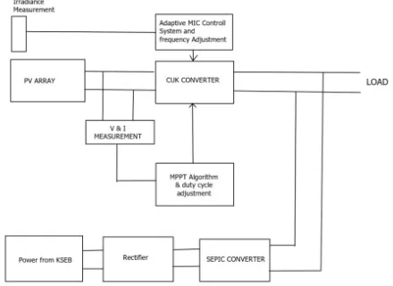
An alternative multi-input rectifier structure is proposed for hybrid wind and solar energy systems as shown in Figure (a) The proposed design is a fusion of CUK and SEPIC converters which remove the need for separate passive
filter and helps step up/down operations for renewable energy sources. A hybrid utility-solar energy system is shown in figure (a), where one of the inputs is connected to the output of the PV array and the other input connected to the output of a AC Grid. The combination of the two converters is obtained by reconfiguring the two-existing diode from each converter and the shared utilization of the CUK output inductor by the SEPIC converter.
(a)
Photovoltaic (PV) technology involves converting solar energy directly into electrical energy by means of a solar cell. For a PV system, the voltage output is a constant DC whose magnitude depends on the configuration in which the solar cells/modules are connected. On the other hand, the current output from the PV system mainly depends on the solar irradiance. The power electronic interfaces used for the PV systems is to convert the generated DC voltage into a suitable ACfor consumer use and utility connection. Generally, the DC voltage magnitude of the PV array is required to be boosted to a higher value by using DC converters before converting them to the utility compatible AC. The DC-AC inverters are then utilized to convert the voltage to 50/60 Hz DC-AC. The process of controlling the voltage and current output of the array must be optimized based on the weather conditions. Specialized control algorithms have been developed called maximum power point tracking (MPPT) to constantly extract the maximum amount of power from the array under varying conditions. The MPPT control process and the voltage boosting are usually implemented in the DC-DC converter, whereas the DC-AC inverter is used for grid-current control.
The PV current increases in strength with the solar irradiance. At high irradiance, the PV-fed MIC can operate in the CCM for a wide load range. Low switching frequencies in that case can contribute to a high efficiency without altering the converter mode of operation to the discontinuous conduction mode (DCM). At low irradiance and due to the low supply current, the converter may move to the DCM. The instantaneous power drawn from input sources is zero at the moment when the inductor current is zero in the DCM [5]. Increasing the switching frequency can keep operation in the CCM. Therefore, the switching frequency is proposed to be adaptively controlled with the solar irradiance as an input.
(b)
Maximum power point tracking (MPPT)or sometimes just power point tracking (PPT) is a technique used commonly with wind turbines and photovoltaic (PV) solar systems to maximize power extraction under all conditions. PV solar systems exist in many different configurations with accordance to their relationship to inverter systems, external grids, battery banks, or other electrical loads. Regardless of the ultimate destination of the solar power, though, the central problem addressed by MPPT is that the efficiency of power transfer from the solar cell depends on the factors that are the amount of sunlight falling on the solar panels and the electrical characteristics of the load. As the amount of sunlight varies, the load characteristic that gives the highest power transfer efficiency changes, so that the efficiency of the system is optimized when the load characteristic changes to keep the power transfer at highest efficiency. This load characteristic is called the maximum power point (MPP) and MPPT is the process of finding this point and keeping the load characteristic there. Electrical circuits can be designed to present arbitrary loads to the photovoltaic cells and then convert the voltage, current, or frequency to suit other devices or systems, and MPPT solves the problem of choosing the best load to be presented to the cells in order to get the most usable power out.
(c)
IV.FUSEDCONVERTER
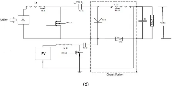
An alternative multi-input rectifier structure is proposed for hybrid wind and solar energy systems as shown in fig (d). The proposed design is a fusion of CUK and SEPIC converters which eliminate the need for separate passive filter and support step up/down operations for renewable energy sources.A hybrid AC grid-solar energy system is shown in fig (d), where one of the inputs is connected to the output of the PV array and the other input connected to AC utility grid generator. The fusion of the two converters is achieved by reconfiguring the two existing diode from each converter and the shared utilization of the CUK output inductor by the SEPIC converter
Mode 1: In this mode both solar energy and Utility is Using, the switches M1 and M2 are turn ON. The capacitors C1 and C2 connected across diode D1 and D2 respectively then diodes D1 and D2 experience reverse biased. The equivalent circuit is as shown in figure (e).
(e)
Mode 2: In this mode only utility is available and solar energy is not available. The switch M1 turns ON and switch M2 turns OFF. The diode D1 experience reverse biased. The inductor current in L3 forces diode D2 to conduct. The equivalent circuit is as shown in figure (f).
(f)
(g)
Mode 4: In this mode only solar energy is available and utility is not using. The switch M1 is turn OFF and switch M2 is turn ON. The current in the inductor L1 forces diode D1 to turn ON and diode D2 experience reverse biased. The equivalent circuit is as shown in figure (e).
(h)
V.EXPERIMENTAL RESULTS
(i)
CUK-SEPIC fused converter was simulated in three different input variations. The graph of gate pulses and output wave form was obtained and verified.
Case 1: The both power sources are available.
(k) Gate pulse in utility part(case 1)
Case 2:Here Solar Source is reduced to 8V. Gate pulse on solar part (M1) is not changing
(l) Gate pulse in utility part(case 2)
Case 3: Solar Source is not Available. Gate pulse on solar part (M1) is not changing.
Output :Figure (n) shows the out of the converter, were its can be observed that the output remains at the reference value in all cases. Figure (o) Shows the current is in continuous Figure 8.7: Continuous conduction mode (CCM) conduction mode at the specified frequency.
(n) Output voltage waveform
(o) Continuous conduction mode
VI.CONCLUSION
cell is activated at high irradiance to retain a high level of power quality. The adaptive MIC control scheme is complemented by an MPPT designed for fast tracking. Thus, by combining the SFM and a fast MPPT, targets of efficiency and power quality are reached. Perturb and observe controller is very simple and can be carried out easily. CUK-SEPIC converter has been proposed for hybrid wind and solar energy system instead of conventional multiple boost converters. The system has following advantages compared to traditional approach: 1) Two boost converters are replaced by single CUKSEPIC fused converter. 2) Additional input filters are not required to filter out high frequency harmonics because of inherent input filter. 3) Energy storage and transfer depends on capacitors of converter. The proposed system offers powerful abilities which are: good tracking efficiency, high response, simple user interface, sophisticated control, high processing speed, real time monitoring and good control for the extracted power, Constant output DC voltage is achieved, Individuals converters are replaced by a common converter and Efficiency of the system is improved
REFERENCES
[1] Suresh KV, A CUK-SEPIC Fused Convrter Topology for Wind and Solar Hybrid systems for Stand-Alone systems, International Journal of Emerging Technology in Computer Science Electronics (IJETCSE) , ISSN: 0976-1353 Volume 14 Issue 2 APRIL 2015 .
[2] Tripti Saha1, Sushma Kakkarl and Deependra Kumar, Fused converter topology for wind-solar hybrid systems.A hybrid energy system combining Photovoltaic(PV) and wind power for grid connected power generation, IEEE Appl. Energy, vol. 66, no. 2, pp. 105111, 2000 [3] MoustafaAdly, Irradiance-Adaptive PV Module Integrated Converter for High Efficiency and Power Quality in Standalone and DC Microgrid
Applications,IEEE Energy Conversion Management, vol. 96, pp. 511520, May 2015.
[4] Ahmed Saeed Ahmed, MPPT Algorithms:Performance and Evaluation, IET Science, Measurement Technology, vol.9, no.3, pp.351-361, May 2015.
[5] N. Mohan, T. M. Undeland, and W. P. Robbins., Power Electronics: Converters, Applications and Design, 3rd ed. New York, NY, USA: Wiley, 2003.
[6] Ahmad Al-Diab, Variable Step Size PO MPPT Algorithm for PV Systems ,12th International Conference on Optimization of Electrical and Electronic Equipment,2010.
[7] A.H. El Khateb, N. Abd.Rahim, J. Selvaraj and B.W. Williams, ”DC-to-DC Converter with Low Input Current Ripple for Maximum Photovoltaic Power Extraction,”IEEE Trans. Ind. Electron., vol.62, no.9, pp.5776-5785, Sept.2015.
[8] N. Mohan, T. M. Undeland, and W. P. Robbins., Power Electronics: Converters, Applications and Design, 3rd ed. New York, NY, USA: Wiley, 2003.