ABSTRACT
HALBUR, JONATHAN CHANDLER. Inorganic Surface Modification of Nonwoven Polymeric Substrates. (Under the direction of Dr. Jesse Jur.)
Inorganic Surface Modification of Nonwoven Polymeric Substrates
by
Jonathan Chandler Halbur
A dissertation submitted to the Graduate Faculty of North Carolina State University
In partial fulfillment of the Requirements of the Degree of
Doctor of Philosophy
Fiber and Polymer Science
Raleigh, North Carolina 2014
APPROVED BY:
______________________________ ______________________________ Dr. Jesse S. Jur, Chair Dr. Joseph Tracy
Department of Textile Engineering Department of Chemical and Chemistry and Science Biomolecular Engineering
______________________________ ______________________________
ii DEDICATION
iii BIOGRAPHY
Jonathan Chandler Halbur was born in June 20, 1986 to John and Kathy Halbur. Jonny has
one older brother, Derrick. He graduated from Athens Drive High School in Raleigh, NC in
May of 2004. He received both his bachelors and masters degrees in Textile Engineering
from the College of Textiles at North Carolina State University. In 2011, he began his
pursuit of a Doctorate of Philosophy in Fiber and Polymer Science in the College of Textiltes
at North Carolina State University. He will join Freudenberg Spunweb Company in Durham,
iv AKNOWLEDGEMENTS
I would like to first acknowledge my advisor Dr. Jesse S. Jur for his support and guidance
though the final part of my career within the College of Textiles at NC State University. As
a new professor with expertise in vacuum science and technology, he introduced me into an
entire new discipline of textile modification and gave me the freedom to develop my own
interests within the field. I am immensely grateful for his constant enthusiasm and
motivation to excel throughout my doctoral research.
I would also like to thank the members my research group, Richard Padbury, Halil Akyildiz,
Nasim Farahbakhsh, Murat Yokus, Yujie Sun, and Kelly Stano, for their friendship,
guidance, and shared successes and failures.
I would also like to thank Dr. Jon Rust, Dr. Jeffery Joines, and Dr. Russell Gorga, whose
enthusiasm and guidance as professors in the College of Textiles helped me develop such a
v TABLE OF CONTENTS
LIST OF TABLES ... vii
LIST OF FIGURES ... viii
Chapter 1. Introduction ...1
1.1Nonwoven production ...3
1.1.1 Spunbond ...5
1.1.2 Meltblown ...8
1.1.3 Electrospinning ...9
1.2Inorganic Surface Modification of Polymeric Substrates ...11
1.2.1 Sol-gel ...12
1.2.2 Direct Application ...15
1.2.3 Sonochemical Synthesis and Deposition ...16
1.2.4 Electroless Deposition ...19
1.2.5 Photoreduction ...19
1.2.6 Physical Vapor Deposition ...21
1.2.7 Chemical Vapor Deposition ...22
1.2.8 Atomic Layer Deposition ...24
1.3Selected Applications for Nanomaterial Modification of Polymeric Substrates ....28
1.3.1 Biomedical Textiles ...28
1.3.2 Filtration ...30
1.3.3 Catalysis ...31
1.4Importance of Surface Energy in Polymer Modification ...34
Chapter 2. Overview of Experimental Approach ...51
Chapter 3. Induced Wetting of Polytetrafluoroethylene by Atomic Layer Deposition for Application of Aqueous-based Nanoparticle Inks ...71
3.1 Introduction ...72
3.2 Experimental Methods ...73
3.3 Results and Discussion ...75
3.4 Summary and Conclusions ...78
Chapter 4. Photoremediation of Heavy Metals from Water onto ZnO coated Fibrous Substrates ...84
vi
4.2 Experimental Methods ...88
4.3 Results and Discussion ...89
4.5 Summary and Conclusions ...93
Chapter 5. Photodeposition of Ag onto Polymer Supported Semiconductor Thin Films Deposited by Atomic Layer Deposition ...103
5.1 Introduction ...104
5.2 Experimental Methods ...106
5.3 Results and Discussion ...107
5.4 Summary and Conclusions ...111
Chapter 6. Nanomaterial Modification of Polymeric Substrates by Physical Methods ..120
6.1 Dip Coating of Au Nanoparticles onto PA-6 ...120
6.2 Drop-on-Demand Ink Jet Printing of Ag Nanoparticles onto Polypropylene ...122
6.3 Sonochemical Deposition of Ag onto Polypropylene ...123
vii LIST OF TABLES
Table 1.1: Summary of inorganic deposition techniques for polymer modification ...13
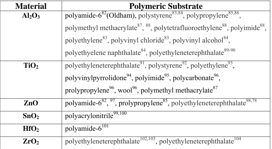
Table 1.2: Summary of ALD onto polymeric substrates ...27
Table 4.1: Photoremediation of single and mixed solutions of Cr6+ and As3+ by ZnO
viii LIST OF FIGURES
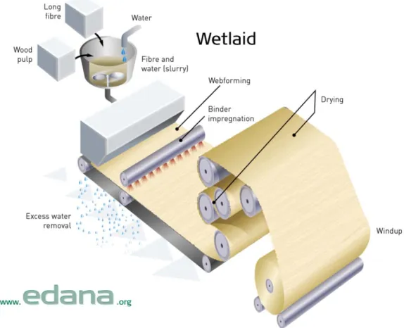
Figure 1.1: Schematic illustration of wetlaid nonwoven production ...4
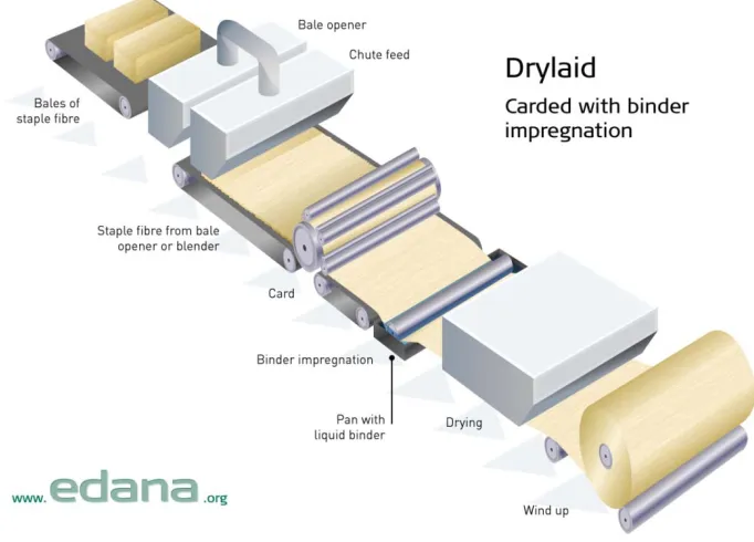
Figure 1.2: Schematic illustration of drylaid nonwoven production ...5
Figure 1.3: Schematic illustration of spunbond nonwoven production ...7
Figure 1.4: Schematic illustration of an electrospinning apparatus ...11
Figure 1.5: Illustration of the sol-gel process ...14
Figure 1.6: Illustration of cavitation events occurring in solution and at a surface ...17
Figure 1.7: Photoreduction of Ag+ ions from solution to TiO2 surface by photoexcited electrons ...21
Figure 1.8: Visual representation of the “ALD window” above and below which growth per cycle is not uniform ...25
Figure 1.9: Illustration of the dosing sequence during a typical ALD process ...24
Figure 1.10: Illustration of electron photoexcitation in a TiO2 nanoparticle in the presence of UV irradiation ...32
ix Figure 2.1: Image of the ALD reactor used in this work (top) and schematic of the ALD
reactor design (bottom) ...52
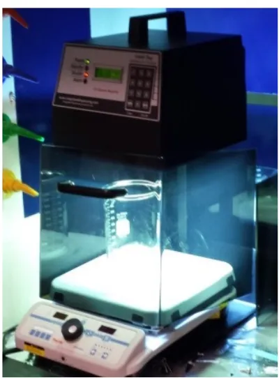
Figure 2.2: Probe sonicator used for nanoparticle dispersion and sonochemical synthesis .
...54
Figure 2.3: UVA curing system for photocatalysis ...55
Figure 2.4: Drop-on-demand ink jet printing system ...56
Figure 3.1: Water contact angle of PTFE films (top) and membranes (bottom) after Al2O3
ALD at 60 (■), 90 (●), and 120(▲) °C ...81
Figure 3.2: Optical microscopy images of drop cast AgNP on a) untreated PTFE film,
and b) PTFE film with 175 cycles Al2O3 ALD at 60 °C, and inkjet printed AgNP on
c)untreated PTFE film, and d) PTFE film with 175 cycles Al2O3 ALD ...82
Figure 3.3: TOF-SIMS mapping of a) C2F4+ ion on untreated PTFE, b) Ag+ on untreated
PTFE, c) C2F4+ on Al2O3 coated PTFE, d) Ag+ on Al2O3 coated PTFE, e) Ag+ ion of
printed line on Al2O3 PTFE ...83
Figure 4.1: Potential implementation schemes of photoactive ZnO coated nonwovens for
toxic ion removal industrially with high power UV illuminants (a) and remotely using solar
x Figure 4.2: Cross-sectional TEM image of winged PET nonwoven fiber ...98
Figure 4.3: Chromium concentration in solution after an exposure of 6 J/cm2 UVA irradiation over 2 hours to PET nonwoven fabrics with 100(■), 300(●), and 500(▲) ZnO
ALD cycles (top) and with 1 in2(■), 2 in2(▲), 3 in2 (●), and 4 in2 (▼) ZnO coated fabric present ...99
Figure 4.4: Log of Chromium concentration in solution after an exposure of 6 J/cm2 UVA irradiation over 2 hours to PET nonwoven fabrics with 100(■), 300(●), and 500(▲) ZnO
ALD cycles (top) and with 1 in2(■), 2 in2(▲), 3 in2 (●), and 4 in2 (▼) ZnO coated fabric present ...100
Figure 4.5: Concentration (top) and log concentration (bottom) of Chromium in solution
after 2 hours of high(●) and low(■) UVA exposure to ZnO ALD coated PET nonwoven
fabrics ...101
Figure 5.1: Optical images of ZnO and TiO2 coated PA-6 nonwoven fabrics during 2
minute exposure to solar radiation. ...115
Figure 5.2: Optical images of ZnO (top) and TiO2 (bottom) coated PA-6 fabrics during 2
minutes of Ag photodeposition with high intensity UVA radiation. ...116
Figure 5.3: Figure 5.3: UV-VIS spectroscopy of Ag photodeposition onto ZnO (left) and
TiO2 (right) ALD coated PA-6 nonwoven fabrics over a two minute irradiation period. ...
xi Figure 5.4: SEM images of Ag photoreduction onto ZnO (a and b) and TiO2 (c and d)
illustrating the unique Ag morphology obtained depending upon the underlying oxide. ...
...117
Figure 5.5: XRD analysis of ZnO (left) and TiO2 (right) ALD on PA-6 nonwoven fabrics
followed by Ag photoreduction ...117
Figure 5.6: ToF-SIMS negative elemental mapping of CNO- (a), Ag- (b), and AgCl2- (c) on Ag decorated TiO2 ALD coated PA-6 nonwovens, and positive elemental mapping of
CNH4+ (d), and Ag+ (e) on Ag decorated ZnO ALD coated PA-6 nonwovens. ...118 Figure 5.7: Patterning of Ag onto photoactive ZnO substrate using a near UV laser and
gantry stage. ...119
Figure 6.1: ToF-SIMS mappings of CN- (a), AlO- (b), and Au- (c) from Au nanoparticles on Al2O3 coated PA-6 nonwoven fabrics. Overlays of AlO- on CN- (d), and Au- on CN
-(e) highlight uniformity differences between Al2O3 ALD and AuNP dip coating ...121
Figure 6.2: Optical image of AgNP ink jet printed onto PP nonwoven coated with 175
cycles Al2O3 ALD ...123
Figure 6.3: Sonication baths and PP fabrics produced by sonication at 15, 30, 45, and 60
xii Figure 6.4: Absorbance spectra of Ag nanoparticle solutions with varying length of
sonication time ...127
Figure 6.5: TOF-SIMS elemental mapping of a) Al+/C2H3+, b) C3H5+, c) 107Ag+, and d) 109Ag+ ions on Ag loaded PP nonwovens ...128
Figure 6.6: UV/VIS spectroscopy of AgNP solutions over time under three different
lighting conditions ...130
Figure 6.7: UV/VIS spectroscopy of photocatalytic degradation of methylene blue using
1
Chapter 1. Introduction
Traditional textiles, flexible woven or knit structures comprising of natural or
synthetic yarns or filaments, are ubiquitous in many areas of society. Since their first reported
use more than 30,000 years ago, textiles produced from natural fibers, either plant or animal,
have become universally present in society for applications such as clothing, décor, storage,
packaging, and protection1. In the early 20th century, the development of synthetic polymers vastly expanded the range of physical and chemical properties that could be tailored for
textile materials. By altering molecular weight, tacticity, repeat unit, or microstructure of
synthetic polymers, a new industry of technical textiles was developed which greatly
increased the prevalence of textiles beyond their predominant role in apparel. Additionally,
the development of nonwoven fabric manufacturing systems allowed the production of low
cost technical textiles. By removing the most time consuming step of fabric manufacture,
weaving or knitting, nonwoven fabrics can be mass produced continuously at speeds orders
of magnitude faster than traditional weaving or knitting.
Surface modification of nonwovens using nanoparticles or thin films represents one
method by which a wide range of properties such as optical absorption, fluorescence,
conductivity, biocompatibility, and catalysis can be imparted to the underlying substrate.2 Historically, textiles are modified using wet processes such as padding, spray coating, and
dip coating because these processes can be utilized in line with the high throughput
continuous processing of textiles. As opposed to inclusion of nanomaterials in the bulk of the
2 deposition enables highly efficient use of the active materials since all of the active materials
can interact with the immediate environment.3 However, achieving uniform surface coatings on polymeric substrates using conventional wet processing can be quite difficult due to
variations in polymer chemistry, textile construction, and processing conditions4,5.
Atomic layer deposition (ALD) is a vapor phase process for nanoscale thin film
deposition of a wide range of inorganic materials based upon the sequential exposures of
organometallic precursors and a co-reactant, which is typically utilized as an oxidant. The
self-limiting nature of ALD allows for precise control of the thin film on the atomic scale,
something impossible to attain through traditional wet deposition techniques on polymers.
Although a relatively new field, the processing of polymers using ALD is described in the
literature for a variety of different polymers; even with variations in the initial nucleation and
growth processes depending on polymer functionality and deposition temperature, conformal
thin films can be successfully grown on almost any polymer surface (see Table 1.1).
Even though the growth mechanism of a variety of inorganic thin films on polymers
has been described, there is minimal literature on their potential applications of industrial
relevance. In addition, methods of processing inorganic-modified polymeric substrates in
combination with traditional textile processing techniques, something that may allow for
universal processing of many different polymers using a single process, has not been
reported. This work will focus on the potential applications of ALD thin films on polymers as
a means of modifying the surface properties of the underlying substrate, and as a means of
imparting photoactive functionality to the polymer. Additionally, the ability to use ALD as a
3 understand the opportunities for surface modification of polymers, fibers, and fabrics, this
review will focus on vapor and wet methods, including ALD. Current issues involved with
these processes on complex structures, such as textiles, will be reviewed. Selected
applications, pertinent to this thesis, of inorganic surface modification to polymeric
substrates will also be summarized.
1.1 Nonwoven Production
The term nonwoven fabric defines a category of textile materials that are formed from fibers
without first converting the individual fibers into yarns.6 Nonwoven textiles can be formed without having to be woven or knitted, which eliminates the most time consuming process in
traditional textile production. Nonwovens can be bonded together by adhesive, thermal and
chemical bonding, or physical entanglement. Engineers have found applications for
nonwovens in a wide range of fields including medical, filtration, automotive, construction,
geotextiles, and agrotextiles. Depending on the specific application, the most common
polymers used for nonwoven production are polyolefins, polyesters, and polyamides.
Although the commercial use of nonwovens ranges from high loft backing materials to flat,
porous filtration media, most traditional uses for nonwoven fabrics have been commodity
goods due to their high throughput, low cost of production, and limited chemical
functionality. However, recent advances in production have provided means for the
formation of nonwoven fibers with sub-micron diameter and controlled porosity. These
4 regeneration, and advanced filtration and barrier systems, and within these emerging fields,
the use of inorganic nanomaterials to enhance or impart advanced functionality will be
critical.
Nonwoven fabrics can be produced from both staple or synthetic fibers and filaments.
Depending upon the polymer and fiber type, the method available for nonwoven production
will vary. For staple fibers of fixed length, webs can be produced either by dry lay and wet
lay processing. Wet lay nonwoven production is analogous to production of paper from wood
pulp, where fibers in a slurry are deposited onto a collection belt and the solution is extracted
(Figure 1.1). Addition of inorganic materials during wet laying can allow for modification of
the nonwoven, although the practice is predominately used only for incorporation of
materials such as glass, carbon, and mineral fibers.7,8
5 Inorganic particles can also be incorporated, although they tend to adversely affect solution
viscosity, have poor solubility in water, can clog spray nozzles, and may require dispersion
or additional steps beyond what is typically performed.7,9-10 Dry laid nonwovens are produced by carding the stable fibers into loose webs followed by crosslapping (Figure 1.2).
Figure 1.2: Schematic illustration of drylaid nonwoven production
1.1.1 Spunbond Processing
6 other two methods being melt blown and flash spinning6. Spunbond webs differ from other spunlaid technologies in that the webs are continuously laid directly from polymer pellet to
fabric in a single step, after which the webs are subsequently bonded (Figure 1.3). There are
four main processes that must be optimized and controlled during the production of
spunbond fabrics: extrusion, drawing, lay-down, and bonding.
The first spunbond process was developed for the production of glass fiber nonwovens by
Owens-Corning Fiberglass Corporation11. The spunbond process starts with the melting of polymer pellets through the use of a screw extruder, where the polymer is mechanically
passed from the feed hopper to the to the filter and heated to a set temperature appropriate for
conversion of the polymer into a molten form (Figure 1.3). During the screw extrusion of the
polymer, additives such as stabilizing agents, dyestuffs, and resin modifiers can be
introduced by the mixing action of the screw. The temperatures and pressures used during
extrusion are determined based upon the polymer being used. After extrusion, the molten
polymer is passed through a filter to remove unmelted polymer and foreign particles, which
can adversely affect the quality of the nonwoven or cause blockages in the spinneret holes.
The polymer then passes through a metering pump to precisely control the volumetric flow
rate of the polymer to the spinpack. Control of polymer temperature during metering and
subsequent delivery to the spinpack is crucial12. The spinpack has two main components: polymer distribution block and a spinneret, which contains thousands of small holes.
Commercial spunbond processes typically place spinnerets side-to-side to create a wider
7 Figure 1.3: Schematic Illustration of spunbond nonwoven production
Molten polymer passes through the spinneret holes and is immediately introduced into a
chilled air stream for quenching. Once quenched, high speed pneumatic attenuation of the
fibers is performed to enhance the molecular orientation of the polymer strands, which
increases the strength of the polymeric filaments. Due to the high speeds of attenuation after
quenching, spunbond nonwoven fabrics are partially oriented and semi-crystalline after
lay-down6. The pneumatic attenuation used for orientation of the polymer strands is also utilized for deposition of the web onto the collection belt. A vacuum under the collection belt is
8 nonwoven web can either be wound onto a roll or continue towards bonding, which can be
accomplished by calendaring, needling, hydroentangling, or chemical bonding13. Most spunbond webs have fiber sizes ranging from 2-20 dtex, but specialized systems can produce
spunbonds ranging from 1 to 50 dtex. Furthermore, by controlling belt speed during laydown,
web basis weight can vary from 10 to 1000 gsm (grams per square meter)14. Controlling the final properties of a spunbond nonwoven can be accomplished through careful polymer
selection and tight control of process parameters such as melt viscosity, melt temperature,
polymer volumetric throughput rate, collection belt speed, bonding method, and bonding
conditions13.
1.1.2 Meltblown
Meltblown fabric processing is very similar to spunbond technology, however the pneumatic
attenuation of the molten polymer exiting the spinneret is performed at very high velocity
using heated air as opposed to the chilled air used in spunbond production. The use of heated
air causes the polymer strands to have much lower diameter than spunbond webs (1-20
microns) since they begin attenuation immediately upon exiting the spinneret rather than
after quenching. Due to the elimination of the quenching step during meltblown production,
the polymer strands impinging upon the collection plate bond to one another such that post
processing of the formed web is not necessary to provide fabric integrity. Air temperature,
polymer and spinneret temperature, polymer volumetric throughput, die-collector distance,
and collector belt speed all influence the final structure and properties of the meltblown web
9 primarily dictated by process temperatures and air flow rate, whereas die-collector distance
directly impacts fabric basis weight, porosity, and degree of thermal bonding15. It should be mentioned that air speed and temperature do have a substantial impact on the thermal
bonding of the meltblown web, but die-collector distance is more easily varied without
affecting as many other physical properties of the polymer fabric. Other parameters, which
cannot be adjusted during production, include air gap, air angle, die setback, and spinneret
orifice diameter affect properties including fiber diameter and fiber distribution.
Optimization of all process parameters allows the production of meltblown fabrics with
isotropic properties.
Similar to spunbond nonwovens, any thermoplastic polymer with a sufficiently low melt
viscosity can be used for the meltblown production. However, polypropylene and polyesters
are traditionally the most common polymers used due to the cost and processability. Due to
the finer diameters and higher control over porosity produced by meltblown nonwovens as
compared to spunbund, meltblown fabrics find use in barrier applications and filtration where
strength is not as crucial16-17. However, approximately two-thirds of meltblown consumption is used in composite structures utilizing spunbonded fabrics in either spunbonded –
meltblown or spunbonded-meltblown-spunbonded layered structures18.
1.1.3 Electrospun
Electrospinning of nonwoven polymeric materials originated when Anton Formhals patented
10 a polymer solution or melt from which the fiber is drawn from the tip of a capillary to a
grounded electrode, which is used as the collector plate. Control of the applied voltage is
critical as it directly influences the speed that the polymer exits the capillary towards the
collector plate. If the applied voltage overcomes the surface tension of the polymer,
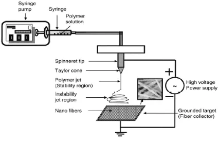
electrospraying will occur and prevent the formation of fibers.20 The most common electrospinning apparatus consists of a spinneret, a collector, and a high voltage power
supply (Figure 1.4). Typically, the spinneret consists of a positive displacement syringe
pump, a syringe, and a needle. During traversal from the capillary tip to the collector, the
polymer liquid jet is stretched and whipped, resulting in nonwoven webs with diameters less
than 1 micron, which limits their mechanical properties. However, the simplicity of
electrospinning setups and the versatility in the nanomaterials that can be deposited make it
one of the most highly studied techniques for nanofiber production even though the
production rate is slow and solvent residue is present. Due to the fine diameters achieved
during electrospinning, webs produced by this method have found application in advanced
filtration systems capable of removing extremely small particles and molecules from both
liquid and air mediums22-23. Additional areas of research involving electrospun nanofibers
11 Figure 1.4: Schematic Illustration of an electrospinning apparatus21
1.2 Inorganic Surface Modification of Polymeric Substrates
The methods for depositing inorganic materials onto polymeric substrates can be categorized
by two groups: liquid and vapor based processes. A summary of the benefits and
disadvantages of the inorganic surface modification techniques detailed in this review are
listed below in Table 1.1. In liquid based processing, nanoparticles or inorganic precursor
compounds are dissolved or solubilized into aqueous or organic solvents and then either
12 phase application involves the reaction or co-reaction of inorganic precursors in the vapor
phase at or near the substrate surface.
For both liquid and vapor based deposition processes utilizing inorganic precursor
compounds, determination as to whether the inorganic material will form nanoparticles or
thin films depends largely on the processing conditions. Many precursor systems exhibit an
island-growth mechanism where nucleation sites form nanoparticles prior to coalescence into
a film. By controlling growth conditions, a variety of unique nanoparticle morphologies can
be deposited prior to film formation.
1.2.1 Sol-gel
An important technique for inorganic modification of polymeric substrates is the sol-gel
method. The sol-gel process is a wet chemical method of preparing ceramic or metal oxide
coatings through the hydrolysis, application, and curing of silica or metal alkoxides onto a
wide range of planar and complex substrates. The process begins through formation of a
“sol”, which is a solution of inorganic precursor compounds (traditionally metal alkoxides)
that can also contain colloidal nanoparticles. Once the suspension of precursors in solution
has been formed, the sol can be applied to planar or complex surfaces through techniques
13 Table 1.1: Summary of inorganic deposition techniques for polymer modification
Technique Benefits Disadvantages
Sol-gel29 temperature, continuous process Easy to add dopants, low
High viscosity with additives, long hydrolysis times, limited control over microstructure
Direct Application
Versatile, simple process, many application techniques, low
temperature, potential for continuous process
Limited to nano- and micro-particles, typically requires binder, limited nanoparticle
concentrations
Sonochemical30
One step synthesis and deposition, low temperature, aqueous, high polymer compatibility, possible to
deposit pure metals
Incompatibility with volatile solvents, degradation to
textile possible
Electroless31
Possible to deposit pure metals, low temperature, fast, possible to
run continuous
Requires Reducing Agent, requires functional surface, difficulty depositing oxides
Photoreduction32
Utilizes UV radiation, low temperature, can deposit pure metals, possible to run continuous
Requires photocatalyst, speed depends on irradiation
strength
PVD33 and CVD34
Wide range of deposition materials, can deposit conformal
coatings, high purity
Require high vacuum , high temperature, line of sight,
batch process
ALD35
Low temperature, conformal films even on high aspect ratio
materials, wide range of deposition materials and
precursors
14 the suspension forms a lyogel layer, which is a 3-dimensional network of solvent and
nanoparticles maintained by secondary bonds36. Careful choice of solvent can ensure that hydrolysis of the precursors does not occur prior to application and for compatibility with the
substrate. After application, the solvent begins to evaporate and the solution will begin to
form a three-dimensional networked gel. The final step is to cure the gel at a specific
temperature to complete the dehydration reactions in the gel and completely remove all
solvent and water byproducts. During curing, a condensation reaction occurs, and the lyogel
dehydrates to a xerogel. A process schematic of the sol-gel process is shown in Figure 1.5.
The drying method and temperature will have a large effect on the density, porosity, and
uniformity of the resultant inorganic network29. Sol-gel is a very useful technique for the formation of nanoparticle doped oxides, aerogels, and bulk ceramic networks.
Figure 1.5: Illustration of the sol-gel process
Physical modification of the formed oxide matrix, or xerogel, is often used to immobilize or
15 either before the hydrolysis of the sol, or after hydrolysis and prior to application on the
textile38. Whether the additive is added before or after hydrolysis does not significantly affect the final composite structure, because the encapsulation or integration occurs during
condensation of the lyogel.
When using sol-gel deposition for polymer modification, careful attention must be paid to
control all processing variables including solution pH, precursor concentration, hydrolysis
time, and curing temperature. Additionally, organic solvents are typically required for sol-gel
processing, as the use of water allows polymerization of the sol during the hydrolysis period,
prior to application. One of the main drawbacks to sol-gel processing of polymers is the long
processing time required to hydrolyze and dehydrate the processing solution and that
achieving a uniform and conformal thin film on complex 3-dimensional substrates is difficult
in the liquid phase due to capillary forces present during application. Sol-gel coatings have
found application in areas such as catalysis39-40, high performance fabrics41,42, and tissue engineering43,44-45.
1.2.2 Direct Application
Direct application of inorganic nanomaterials onto the surface of polymers is a versatile
method for nanomodification of complex surfaces. Direct application can be accomplished
through techniques such as dip-coating, spray-casting, drop-casting, and spin-coating, ink jet
printing, padding, and screen printing. The basis for all direct techniques involves dispersing
16 solution, and then removing the solvent. After completion of solvent removal the desired
nanomaterial is left on the polymer surface. When dip coating or spin coating materials, the
concentration of the inorganic material, removal or spinning speed, and evaporation
conditions all have a large impact on the uniformity and thickness of the coating.
Additionally, the surface energy and wettability of the polymeric substrate being uses has a
large impact on the ability to directly apply inorganics in solution form. Direct
nanomodification of polymers is one of the most practiced roll-to-roll methods for
antibacterials and patterened flexible systems.
1.2.3 Sonochemical Synthesis and Deposition
Sonochemistry is a field dealing with the use of acoustic waves as a form of energy input into
a system. Sonochemical irradiation is unique as an energy source in the fact that the acoustic
waves input into the liquid medium are not what actually cause chemical reactions to occur.
Instead, when acoustic waves irradiate a solution, the alternating expansive and compressive
waves produce small bubbles that oscillate. When these bubbles reach a maximum size
(typically tens of µm), an unstable state is formed and the bubbles, or cavities, violently
collapse. The cavitation process createslocalized temperatures and pressures of ~5000 K and
~1000 bar.30 Due to the size and time scale of cavitation events, the surrounding bulk liquid medium stays at ambient conditions although heat transfer occurs with the liquid surrounding
the cavity (Figure 1.6). Sonochemistry was initially used for the sonolysis of metal carbonyl
17 ligands during cavitation and the resultant metal atoms aggregate into metallic powders30. If surfactants or other stabilizing agents are present during the reduction process, nanoparticles
of varying morphology can be formed. If the precursor is volatile, the reaction will take place
in the vapor phase within the cavity, and amorphous products are formed due to the
extremely short reaction periods. However, non-volatile precursors react in a 200 nm ring
surrounding the cavity and the bulk of the liquid, where temperatures are ~1900 °C as
measured by luminescence events. Through cavitation a wide range of oxides, sulfides,
carbides, and metals can be synthesized.
Figure 1.6: Illustration of cavitation events occurring in solution and at a surface
Sonochemical reduction of noble metal salts in aqueous solutions also has the benefit of not
18 create secondary radical species can greatly increase the reduction rate47,48. The formation and reduction of noble metals, as demonstrated with Ag+, by sonolysis of water is shown below30:
Sonication can also be used to simultaneously synthesize and deposit nanomaterials onto a
substrate in a one-step process48-49. When cavitation occurs near the surface of a solid in solution, the collapse of the cavity becomes asymmetrical and microjets form in the direction
of the solid to compensate. These microjets have speeds as high as 100 m/s and when
combined with the cavitation conditions are capable of locally depositing nanoparticles into
the substrate (Figure 1.6). Two main conditions can result in the deposition of nanoparticles
onto a substrate in solution: chemical bonding or interaction with the substrate and localized
melting. In the case of solid substrates such as silicon, strong chemical interactions are
formed as the atoms are reduced during cavitation, which serves as a nucleation site for
Reactive Species Formation
H
2O
H• + OH •
H • + H •
H
2H • + OH •
H
2O
RH • + H • (or OH •)
R • + H
2O (or H
2)
OH • + OH •
H
2O
2Noble Metal Reduction
Ag(I) + H
Ag(0)
or
19 subsequent reduction events.30 When cavitation occurs at the surface of a polymer, localized melting occurs and the microjets deposit the formed nanoparticles into the outer nanometers
of the polymer49. In both cases, the deposited nanoparticles strongly adhere to the surface of the substrate and are durable to washing and even subsequent sonication in some
instances50,49.
1.2.4 Electroless Deposition
Electroless deposition is a widely used method for the formation of metal nanoparticles and
thin films on the surface of nonconductive substrates. Unlike electroplating, where an applied
current is utilized to reduce metal ions from solution to the substrate surface, a reducing
agent is used. The reducing agent chosen depends largely on the processing conditions being
used and the desired structure of the nanomaterial being deposited. Electroless deposition is
most commonly used as a means for reduction of copper51 and nickel52,53, from solution for electronic applications. Nanoparticles and thin films of noble metals such as gold54, silver55, and platinum54 have also been demonstrated. When depositing onto surfaces with a lack of
functionality to facilitate nucleation, solution based etching or plasma treatment can be used
to enhance surface reactivity.56
1.2.5 Photoreduction
Similar to electroless deposition, photoreduction is a method for the formation of inorganic
20 require the presence or use of a reducing agent or any other auxiliaries. Instead, irradiation of
a photoactive solution or substrate with UV light results in the formation of reactive species
necessary for reduction. Even in the absence of a catalyst, UV irradiation can hydrolyze
water and reduce Ag+ ions, but the photo-oxidation of water proceeds slowly. As such, photocatalyst materials are typically used to generate photo-excited radical species in the
liquid medium. When a semiconductor photocatalyst absorbs UV radiation with energy
larger than its band gap, electrons from the valence band are excited to the conduction band
of the material where they can interact with metal ions present in the solution, as shown in
Figure 1.7 with TiO2 and Ag+ ions. The use of photoreduction for the modification of
polymers is more difficult, as the presence of photocatalyst species is a pre-requisite for the
reduction process. However, photocatalysts can be deposited onto polymers through
techniques such as sol-gel57,58, hydrothermal59, and atomic layer deposition60,61 among other techniques. In such a case where the photocatalyst is present on the surface of the polymer,
exposure of the treated substrate to UV irradiation in the presence of a metal salt results in
deposition of metals and oxides directly onto the photocatalyst. The two most common
photocatalysts used for photoreduction are ZnO and TiO2 due to a wide variety of deposition
21 Figure 1.7: Photoreduction of Ag+ ions from solution to TiO2 surface by photoexcited
electrons
1.2.6 Physical Vapor Deposition
Physical vapor deposition (PVD) is a vapor phased deposition technique that is used both
commercially and in academia to deposit a variety of inorganic materials onto the surface of
polymeric materials. Materials that can be deposited by PVD include metals and metal oxides
22 free path of the gaseous inorganic species is larger than the distance from the target source
material to the substrate. The target used during evaporative PVD has the same chemical
composition as the material being deposited, thus the resultant inorganic can be highly pure.
The target material travels through the chamber until it impinges upon a surface cool enough
re-condense the vapor phase atoms. However, the heat required to evaporate many targets for
PVD exceed the thermal stability of many commercial polymers, limiting the use of the
technique to depositing onto polymers with very high thermal stability and inorganics.
Additionally, since the vaporized atoms travel directly from the target to the surface of the
substrate, the deposition proceeds in a line of site manner such that complex substrates, such
as nonwovens, will not be uniformly coated63.
The use of high energy plasma to sputter atoms from the surface of the target can also be
used in sputtering PVD processes. In this case, a plasma formed near the target etches atoms
or molecules directly from the target towards the substrate. One advantage of sputtering over
evaporation for PVD is that metal oxides can be sputtered stoichiometrically from a single
target63. Additionally, plasma sputtering is highly compatible with a wide range of polymeric substrates, allowing for a diverse range of materials to be deposited. As with evaporation,
deposition is characterized by line of sight and cannot uniformly coat complex surfaces such
as nonwovens or materials with high aspect ratios.
1.2.7 Chemical Vapor Deposition
23 reaction or decomposition of one or more vapor phase precursors on or near the surface of a
substrate. The technique is capable of depositing not only pure metals and metal oxides, but
also metal nitrides, sulfides, carbides, and arsenides34-66. Although conformal coating of high aspect ratio substrates is limited, an important feature of CVD over PVD is that it is not line
of sight under most processing conditions. The precursors used for CVD also have vapor
pressures such that the process can operate in the viscous flow regime, where the mean free
path of the inorganic precursors is much shorter than the distance from the precursor source
to the substrate. The deposition rate in CVD is predominately controlled by the flux of
precursor molecules onto the substrate surface and the sticking coefficient of the
precursor-substrate coupling. The low sticking coefficient of CVD systems means that many
interactions between the precursor and substrate may be necessary to cause reaction or
decomposition, resulting in highly conformal films as compared to PVD. However, if during
CVD the gas phase precursors react or decompose prior to interaction with the substrate
surface, particles can be deposited onto the substrate surface in line of sight fashion, which is
undesirable and non-uniform.
Due to the versatility of the CVD process to deposit conformal thin films of varied
composition onto a wide range of substrates, it has found application in semiconductors, gas
diffusion barriers, catalysis, and optical coatings34,67,68. Some materials deposited by the CVD process require the gas phase reaction between two vapor phase precursors near the
surface of the substrate, and in these cases it can be difficult to uniformly coat complex high
24 nonwoven polymer mats. Additionally, the temperatures required for some CVD systems fall
outside of the thermal stability of most commercially important polymers.
1.2.8 Atomic Layer Deposition
In order to get more uniform coverage on difficult substrates, the CVD process was modified
to develop what is now called atomic layer deposition. Atomic layer deposition is a vapor
phase thin film and nanoparticle deposition technique based upon the sequential self-limiting
surface reactions of two vapor phase precursors. The technology was developed in the 1970’s
by Suntola, utilizing ALD processing for the deposition of ZnS in luminescent displays69. By separating exposure of the two precursors to the substrate surface, undesirable gas phase
reactions between precursor species are eliminated, preventing non-uniform film growth or
vapor-phase particle deposition. A generalized ALD process is shown in Figure 1.8. By
operating the deposition process below the thermal decomposition temperature of the
precursor’s, the only reactions able to process take place at available sites on the surface of
the substrate. As exposure to the precursors occurs, all available sites react with the precursor
until the surface is saturated with chemisorbed precursor, at which point an inert purge is
utilized to remove all physically adsorbed species from the surface. As a result, ALD is
self-limiting in nature and uniform growth per cycle (GPC) can be obtained on a wide variety of
complex high aspect ratio and three dimensional structures.
In order to achieve uniform GPC using ALD, two main conditions must be met. First, the
25 upon the material being deposited and the specific precursors being used. An illustration of
the ALD is shown in Figure 1.8.
Figure1.8: Visual representation of the “ALD window” above and below which growth per
cycle is not uniform
If the substrate temperature is below the ALD window, precursor can condense onto the
substrate surface and increase growth, or the thermal energy of the system may be
insufficient to allow surface reactions to occur.35 Similarly, substrate temperatures above the ALD window also cause non-uniform growth. Lower growth may be observed due to
evaporation of the precursors from the substrate, or higher growth can be caused by thermal
26 uniform ALD growth is that sufficient precursor must be dosed in order to saturate all
available surface reactive sites, and any physically adsorbed precursor present after dosing
must be removed from the substrate by an inert purge. In the case of ALD deposition onto
high surface area substrates such as textiles, correct dosing and purging conditions become
increasingly important as available surface functionality and precursor diffusion differ vastly
from traditional planar substrates utilized originally for ALD.
Figure 1.9: Illustration of the dosing sequence during a typical ALD process
27 temperature processes have been developed, allowing for deposition pure metals, oxides, and
nitrides onto a wide variety of polymers, a summary of which is provided in Table 1.2. Use
of ALD modification on polymers has been utilized to increase gas and water vapor barrier
properties for application in electronic device encapsulation and certain packaging
applications71-72, but application has expanded to modify polymer surface energy73,74 and wetting properties75, create organic electric devices76, enhance biocompatibility77, impart catalytic properties78,79-80, and sensing81.
Table 1.2: Summary of ALD onto polymeric substrates
Material Polymeric
Substrate
Al2O3 polyamide-682(Oldham), polystyrene83,84, polypropylene85,86,
polymethyl methacrylate87, 88, polytetrafluoroethylene88, polyimide88,
polyethylene83, polyvinyl chloride83, polyvinyl alcohol84, polyethyelene naphthalate84, polyethyleneterephthalate89-90
TiO2 polyethyleneterephthalate
91,polystyrene92, polyethylene93,
polyvinylpyrrolidone94, polyimide95, polycarbonate96,
prolypropylene96, wool96, polymethyl methacrylate87
ZnO polyamide-682, 97, prolypropylene85, polyethyleneterephthalate98,78 SnO2 polyacrylonitrile99,100
HfO2 polyamide-6101
28
1.3 Selected Applications of Nanomaterials on Textile
Substrates
Applications of textiles within various industries are expansive, and the modification of these
materials using nanomaterials only further enhances their utility. This section will focus on
the use of nanomaterials in relation nonwovens used for biomedical, filtration, and catalysis,
but there are many other applications for textile nanomodification that are not immediately
related to this research.105
1.3.1 Biomedical Textiles
Textile substrates find wide use in the medical industry in the form of sutures, gowns, sheets,
tissue and bone scaffolds, wound dressings, and many more.106 Traditional textiles and nonwovens in the medical field are most often commodity goods used in low-cost, disposable
applications. However, the ability to engineer the surface of polymer materials at the
nanoscale offers extensive application in advanced biomedical areas such as tissue
engineering, wound dressings, and drug delivery.3
One of the major issues facing patients around the world is organ injury and organ failure.
Two current viable options available for organ damage remediation are transplantation and
biotextile implantation. Traditional transplantation of donor organs is not only a difficult
29 response from the host even with the wide availability of pharmaceuticals for prevention of
such responses. Development of suitable scaffold materials for tissue engineering and organ
regeneration is a promising path to reducing the dependency on organ transplantation.
Recently, the use of electrospinning for the production of tissue scaffolds has received much
attention due to the ability to produce biocompatible, bioresorbable, highly porous, three
dimensional scaffold materials that mimic the extracellular matrix, which must provide a
surface for cellular adhesion, proliferation, and retention of differentiated cells26,107-108. However, there is still need to modify the surface of these scaffold materials to promote
cell-cell and cell-cell-matrix interactions.
The surface properties of the scaffold as well as its morphology must meet stringent
requirements as it is in direct contact with the cells and tissue of the host. Surface
functionality affects the binding of protein to the scaffold when first coming into contact with
the body fluids (in vivo) or cell culture medium (in vitro)109,110. In addition to available functional groups on the textile surface, the surface energy of the scaffold material plays an
important role in cell adhesion, as it relates directly to the hydrophilic or hydrophobic nature
of the scaffold. For application in vascular stents and heart valves, a hydrophobic surface is
desired as it prevents cellular adhesion that can cause thrombosis after implant. In contrast,
hydrophilicity is required for scaffolds to promote cell adherence and growth, but negatively
30
1.3.2 Filtration
Woven and nonwoven filtration media find wide application in electronic, medical,
pharmaceutical, and biological industries where filters must be engineered to meet stringent
collection efficiencies at minimal pressure drop113,114. Although the predominant application of fibrous filter media is for air and gas stream filtration, liquid filtration using polymer
membranes is also being researched115,116,23.
In contrast to air filtration, where the fibrous medium does not tend utilize surface treatment
beyond that of electrostatic charging, liquid filters require a wide range of surface
functionalities depending on the liquid medium and the types of nutrients, particles, and
organisms present. Within the field of liquid filtration, micro- and nano-filtration have
observed accelerated growth due to their low cost, minimal footprint, low operating pressure,
and efficiency at removing a wide range of contaminants. A common application for this
filter media is in natural and wastewater filtration, where large quantities of organic matter,
macromolecules, colloids, and microorganisms may be present. As a result, fouling from
organic, colloidal, and biological sources can occur during use. Biofouling of membrane
filters has the most detrimental impact on performance due to lowering flux, increasing
operating pressure, reducing filtration efficiency, and shortening filter life117. By tailoring the surface chemistry of the membrane, reduction of fouling properties can be achieved114,118. Liu et al. utilized Ag nanoparticles in polysulfone membranes to impart antiadhesive and
31 also needed to modify the polymer surface chemistry to enhance the hydrophilic nature of
membranes made from polymers such as PTFE, PP, and others73,119,120. These materials exhibit excellent UV and chemical resistances, but their hydrophobic nature prevents their
use in aqueous systems. However, nanoscale modification of the polymer surface by plasma,
wet chemical, or vapor phase processing can induce a wetting transition, eliminating aqueous
incompatibility.
1.3.4 Catalysis
Catalysis can be generally described as the use of an active catalyst material to increase the
rate of a chemical reaction. The distinction between a catalyst and other chemical
components that may participate in a chemical reaction is that the catalyst is not consumed.
Various n-type semiconductor metal oxides including TiO2, ZnO, SnO2, and WO3, have been
utilized for the photocatalytic elimination or reduction of organic pollutants, metal ions, and
biomolecules in both air and water.121, 122
Photocatalytic materials are used for three main applications: photovoltaic generation of
energy, photocatalytic oxidation, and photocatalytic reduction. In all three instances the
photoactivity is a direct result by absorption of photons of greater energy than the band gap
32 Figure 1.10: Illustration of electron photoexcitation in a TiO2 nanoparticle in the presence of
UV irradiation.
Electron photoexcitation from the valence band to the conduction band produces electron (e
-)-hole (h+) pairs. The photoexcited electrons and holes are then able to take part in reduction
and oxidation reactions, respectively. In many cases, oxidation reactions are favored due to
the higher redox potential of h+, 2.5V, over e-, -0.5V (redox values are averages with respect
to the standard hydrogen electrode at pH=7). An overview of the oxidation and reduction
reactions for TiO2 in water are shown below122.
TiO2 + hv e-+ h+
-33 O2- + h+ HO2·
HO2· + h+ H2O2
H2O2 + hv OH· + OH·
The issues with the use of these materials for photocatalysis are that they have large band
gaps, requiring UV light for photoexcitation, they tend to be instable in aqueous solutions,
causing photodegradation, and the electron-hole recombination rates for excitons are high,
limiting oxidation and reduction reactions to be carried out. Of the available photocatalysts,
TiO2 and ZnO are of particular interest due to their lower band gap (~3.3 eV), allowing
photoactivity under UVA (315-400 nm) irradiation, and photoinduced hydrophilicity.
Although ZnO has a higher electron mobility, which allows higher activity of the
photogenerated excitons, ZnO photocatalysts in water photodegrade and self-deactivate in
the presence of photogenerated holes, leaching Zn2+ ions into solution.123 However, the presence of metal nanoparticles on the surface of ZnO can prevent the photodegradation of
the photocatalyst through oxidation of the metal. TiO2 is widely accepted as the best
photocatalyst because of its high chemical stability, strong oxidizing power, low cost, and
non-toxicity, although ZnO exhibits the same properties with only less stability. Because of
their non-toxicity, both ZnO and TiO2 photocatalysts can be found in household items such
as toothpaste, paint, sunscreen, and pharmaceutical drugs.124
34 does the amount of catalyst and its activity affect the reaction rate, but also the diffusion of
reactants and byproducts from the surface of the catalyst material. As such, maximizing the
active surface area of heterogeneous catalysts is crucial. High surface area substrates such as
activated carbon, anodic aluminum oxide, foamed glass, mesoporous silica, surface coated
micro- and nano-beads, nanoparticles, nanorods, and nanofibers. Polymeric nanomaterials
that can serve as substrates for deposition of photocatalyst materials are of large interest due
to their low cost, ease of processing, and variable chemistry and morphology. A variety of
polymers have been utilized as photocatalyst supports including polyamide-6, polyesters,
polystyrene, polytetrafluoroethylene, polyethersulphone, polyvinylidene fluoride,
polycarbonate, polysulphone, polyacrilonitrile, and polypropylene. Polymers such as PAN,
PET, PA-6, and PP are of particular interest as they can be meltblown and electrospun to
form nanofiber mats with very high surface area.
1.4 Importance of Surface Energy in Polymer Modification
In order to understand how to process a polymer to add functionality through inorganics, the
basic principles of surface energy and wetting are necessary to understand. Differentiation of
the surface energy and wettability is important, as surface energy is a thermodynamic value
of the polymer, whereas wettability describes how well a fabric adsorbs, absorbs, and allows
penetration of water on and through the polymer surface. Measurement of the contact angle
of a liquid on the surface of a planar material is a method for quantitatively assessing the
35 like polymers and fabrics, factors such as surface morphology, fabric construction, and fabric
basis weight can also have a direct effect on the wettability of a given polymer substrate. The
contact angle of a liquid on a polymer surface directly relates the interactions of the liquid
droplet, polymer substrate, and gas environment, as shown in Figure 1.10.
Figure 1.11: Contact Angle Measurement
A contact angle of 90° is considered to be transitional point between hydrophilic and
hydrophobic. If the contact angle is 0°, then the solid-liquid interaction is greater than or
equal to that of the liquid-liquid interaction. Conversely, a contact angle of 180° implies no
interaction between the solid and liquid phases. When the contact angle exceeds 90°, the
interaction between the liquid and gas phases is greater than the interaction between the
liquid and solid phases, which relate to the ability of the surface to form secondary bonds
36 To understand the interactions of the three phases; Gibbs’ equation can be used. As shown in
Equation 1.1, Gibbs’ equation gives the sum of the three interfacial energy of a system, F,
where A is the area and γ is the surface energy per unit area of the given phases.
F = ASγSV + ALγLV= ΣAγ (Eqn. 1.1)
Spontaneous wetting of a planar surface only occurs when the change in free energy, ΔF, of
the system becomes negative as a result of the contact between the liquid and solid phases,
presented in Equation 1.2.
ΔF = F2-F1 = Σ(Aγ) 2 - Σ(Aγ)1 (Eqn. 1.2)
When the liquid is introduced into the system, the solid-vapor interface is replaced with the
solid-liquid interface, and the change in energy of the system is a result of the work done by
the liquid on the surface. If a liquid is not absorbed or adsorbed to the surface, then a
thermodynamic equilibrium will be met between the solid, liquid, and vapor interfaces.
Young’s equation (Equation 1.3), makes a relation between the surface energies of the three
phases (Equation 1.1) and the contact angle of the liquid on the solid surface.
γLV (cos θ) = γSV - γSL (Eqn. 1.3)
It should be noted that Young’s equation is based upon a perfect planar surface that is smooth
37 never uniform, there can be large variability in repellency data between planar polymers and
their fabrics.
The Cassie-Baxter and Wenzel models address surface roughness when measuring contact
angle and relate the apparent contact angle measured on the roughened surface (θ*) to the
contact angle that would be measured on a flat surface (θ). Wenzel’s model (Equation 1.4)
considers the situation where the entire surface can be wet, where Wenzel’s roughness factor,
r, is defined as the ratio of the actual area contacted by the drop relative to the drops
projected area.
cos θ* = r cos θ (Eqn. 1.4)
Wenzel’s model is useful when measuring planar substrates with surface roughness present,
but when assessing fibrous substrates, the roughness factor becomes very large and contact
angle is difficult to assess. The Cassie-Baxter model for wetting regards a system where the
droplet onto interacts with the substrate at the peaks of a porous substrate, where φs and φv
are defined as the factional area of the droplet in contact with the solid and air, respectively.
cos θ* = φs cos θ - φv (Eqn. 1.5)
In the Cassie-Baxter model, a metastable system is possible where a hydrophilic surface
cannot be wet due to the high fractional area with the air, which is considered a perfectly
hydrophobic medium (i.e. cos θ = -1). In the metastable state, perturbation of the liquid
38 References
1. Sampath, M. R., Frequently Encountered Problems in Textile Wet Processing and a Diagnostic Approach for Prevention/Solutions. Colourage 2002,49 (2), 79.
2. Hegemann, D.; Oehr, C.; Fischer, A., Design of functional coatings. Journal of Vacuum Science & Technology A 2005,23 (1), 5-11.
3. Thomas, B. P., A Review of Wet-Laid Nonwovens Manufacturing and Markets.
INDA-TEC 1993: Book of Papers. Nonwovens Technologies 1993, 247.
4. Knobelsdorf, C.; Lützkendorf, R., Opportunities and possibilities for new products based on wet-laid process. Technical Textiles / Technische Textilen 2009,52 (2),
E66-E67.
5. Karwa, A. N.; Barron, T. J.; Davis, V. A.; Tatarchuk, B. J., A novel nano-nonwoven fabric with three-dimensionally dispersed nanofibers: entrapment of carbon nanofibers within nonwovens using the wet-lay process. Nanotechnology 2012,23 (18).
6. Zhu, M. J.; Xu, G. B.; Yu, M. F.; Liu, Y. B.; Xiao, R., Preparation, properties, and application of polypropylene micro/nanofiber membranes. Polymers for Advanced Technologies 2012,23 (2), 247-254.
7. Li, M. F.; Xiao, R.; Sun, G.; Donghua Univ, C. T., Preparation and Properties of Poly (trimethylene terephthalate) Nanofiber Membrane. 2011; p 258-263.
8. Smorada, R. L., Nonwoven Fabrics, Spunbonded. Kirk-Othmer Encyclopedia of Chemical Technology, 2004.
9. Slayter, G.; Thomas, J. H. Manufacture of Glass Wool. 1940.
10. Lim, H., A Review of Spun Bond Process. Journal of Textile and Apparel, Technolgy and Management 2010,6 (3), 1-13.
11. Malkan, S. R., An overview of spunbonding and meltblowing technologies. TAPPI Journal 1995,78 (6), 185-190.
12. Bhat, G. S.; Nanjundappa, R.; Kotra, R., Development of structure and properties during spunbonding of propylene polymers. Thermochimica Acta 2002,392,
39 13. Dutton, K. C., Overview and Analysis of the Meltblown Process and Parameters.
Journal of Textile & Apparel Technology & Management (JTATM) 2009,6 (1), 1-24.
14. Brochocka, A.; Makowski, K.; Majchrzycka, K., Penetration of different
nanoparticles through melt-blown filter media used for respiratory protective devices.
Textile Research Journal 2012,82 (18), 1906-1919.
15. Burton, N. C.; Grinshpun, S. A.; Reponen, T., Physical collection efficiency of filter materials for bacteria and viruses. Annals of Occupational Hygiene 2007,51 (2),
143-151.
16. Gerard, E.; Bessy, E.; Salvagnini, C.; Rerat, V.; Momtaz, M.; Henard, G.; Marmey, P.; Verpoort, T.; Marchand-Brynaert, J., Surface modifications of polypropylene membranes used for blood filtration. Polymer 2011,52 (5), 1223-1233.
17. Ugur, S. S.; Sener, S.; Karaboyaci, M.; Sgem, A NOVEL DESIGN APPROACH FOR GEOTEXTILES USED IN SOLID WASTE DISPOSAL SITES. 10th International Multidisciplinary Scientific Geoconference: Sgem 2010, Vol Ii 2010,
361-368.
18. Yang, Z. Z.; Lin, J. H.; Tsai, I. S.; Kuo, T. Y., Particle filtration with an electret of nonwoven polypropylene fabric. Textile Research Journal 2002,72 (12), 1099-1104.
19. Ward, G. F., Meltblown nanofibres for nonwoven filtration applications. Filtration & Separation 2001,38 (9), 42-43.
20. Murugan, R.; Ramakrishna, S., Design strategies of tissue engineering scaffolds with controlled fiber orientation. Tissue Engineering 2007,13 (8), 1845-1866.
21. Agarwal, S.; Greiner, A.; Wendorff, J. H., Electrospinning of Manmade and Biopolymer Nanofibers-Progress in Techniques, Materials, and Applications.
Advanced Functional Materials 2009,19 (18), 2863-2879.
22. Qin, X. H.; Wang, S. Y., Filtration properties of electrospinning nanofibers. Journal of Applied Polymer Science 2006,102 (2), 1285-1290.
23. Pan, Y. J.; Chuang, W. S.; Lin, C. Y.; Chu, C. H., Composited Silver-contained PA 6 electrospun fibers with spunbond nonwovens for filtration applications. In
Applications of Engineering Materials, Pts 1-4, Bu, J. L.; Wang, P. C.; Ai, L.; Sang,
X. M.; Li, Y. G., Eds. 2011; Vol. 287-290, pp 2626-2629.
24. Sundarrajan, S.; Balamurugan, R.; Kaur, S.; Ramakrishna, S., Potential of Engineered Electrospun Nanofiber Membranes for Nanofiltration Applications. Drying
40 25. De Vrieze, S.; Daels, N.; Lambert, K.; Decostere, B.; Hens, Z.; Van Hulle, S.; De
Clerck, K., Filtration performance of electrospun polyamide nanofibres loaded with bactericides. Textile Research Journal 2012,82 (1), 37-44.
26. Huang, L. W.; Manickam, S. S.; McCutcheon, J. R., Increasing strength of
electrospun nanofiber membranes for water filtration using solvent vapor. Journal of Membrane Science 2013,436, 213-220.
27. Tomer, V.; Teye-Mensah, R.; Tokash, J. C.; Stojilovic, N.; Kataphinan, W.; Evans, E. A.; Chase, G. G.; Ramsier, R. D.; Smith, D. J.; Reneker, D. H., Selective emitters for thermophotovoltaics: erbia-modified electrospun titania nanofibers. Solar Energy Materials and Solar Cells 2005,85 (4), 477-488.
28. Gai, G. Q.; Wang, L. Y.; Dong, X. T.; Xu, S. Z., Electrospun
Fe3O4/PVP//Tb(BA)(3)phen/PVP magnetic-photoluminescent bifunctional bistrand aligned composite nanofibers bundles. Journal of Materials Science 2013,48 (15),
5140-5147.
29. Tran, C.; Kalra, V., Fabrication of porous carbon nanofibers with adjustable pore sizes as electrodes for supercapacitors. Journal of Power Sources 2013,235, 289-296.
30. Fu, S. Z.; Yang, L. L.; Fan, J.; Wen, Q. L.; Lin, S.; Wang, B. Q.; Chen, L. L.; Meng, X. H.; Chen, Y.; Wu, J. B., In vitro mineralization of hydroxyapatite on electrospun poly(epsilon-caprolactone)-poly(ethylene glycol)-poly(epsilon-caprolactone) fibrous scaffolds for tissue engineering application. Colloids and Surfaces B-Biointerfaces
2013,107, 167-173.
31. Hu, J.; Wei, J. C.; Liu, W. Y.; Chen, Y. W., Preparation and characterization of electrospun PLGA/gelatin nanofibers as a drug delivery system by emulsion
electrospinning. Journal of Biomaterials Science-Polymer Edition 2013,24 (8),
972-985.
32. Jia, L.; Prabhakaran, M. P.; Qin, X. H.; Kai, D.; Ramakrishna, S., Biocompatibility evaluation of protein-incorporated electrospun polyurethane-based scaffolds with smooth muscle cells for vascular tissue engineering. Journal of Materials Science
2013,48 (15), 5113-5124.
41 34. Huang, Z. M.; Zhang, Y. Z.; Kotaki, M.; Ramakrishna, S., A review on polymer
nanofibers by electrospinning and their applications in nanocomposites. Composites Science and Technology 2003,63 (15), 2223-2253.
35. Li, D.; Wang, Y. L.; Xia, Y. N., Electrospinning of polymeric and ceramic nanofibers as uniaxially aligned arrays. Nano Letters 2003,3 (8), 1167-1171.
36. HyeonLee, J.; Beaucage, G.; Pratsinis, S. E., Aero-sol-gel synthesis of nanostructured silica powders. Chemistry of Materials 1997,9 (11), 2400-2403.
37. Hench, L. L.; West, J. K., THE SOL-GEL PROCESS. Chemical Reviews 1990,90
(1), 33-72.
38. Mahltig, B.; Haufe, H.; Bottcher, H., Functionalisation of textiles by inorganic sol-gel coatings. Journal of Materials Chemistry 2005,15 (41), 4385-4398.
39. Mahltig, B.; Textor, T., Combination of silica sol and dyes on textiles. Journal of Sol-Gel Science and Technology 2006,39 (2), 111-118.
40. Ness, S. R.; Dunham, G. E.; Weber, G. F.; Ludlow, D. K., SCR catalyst-coated fabric filters for simultaneous nox and high-temperature particulate control. Environmental Progress 1995,14 (1), 69-74.
41. Tudorachi, N.; Lipsa, R., Poly(vinyl alcohol)-g-Lactic Acid Copolymers and Films with Silver Nanoparticles. Journal of Applied Polymer Science 2011,122 (2),
1109-1120.
42. Meille, V., Review on methods to deposit catalysts on structured surfaces. Applied Catalysis a-General 2006,315, 1-17.
43. Muduli, S.; Game, O.; Dhas, V.; Vijayamohanan, K.; Bogle, K. A.; Valanoor, N.; Ogale, S. B., TiO2-Au plasmonic nanocomposite for enhanced dye-sensitized solar cell (DSSC) performance. Solar Energy 2012,86 (5), 1428-1434.
44. Uddin, M. J.; Cesano, F.; Scarano, D.; Bordiga, S.; Zecchina, A. In Effect of Ag and Au Doping on the Photocatalytic Activity of TiO2 Supported on Textile Fibres,
Symposium on Materials for Nanophotonics - Plasmonics, Metamatgerials and Light Localization held at the 2009 MRS Spring Meeting, San Francisco, CA, Apr 14-17; San Francisco, CA, 2009; pp 153-159.
45. Xu, A. W.; Gao, Y.; Liu, H. Q., The preparation, characterization, and their
photocatalytic activities of rare-earth-doped TiO2 nanoparticles. Journal of Catalysis