Solution of the Moving Oscillator Problem
using the Newmark's β Method
Mehmet Akif Koc1, - Ismail Esen2– Huseyin DAL3
Research Assistant, Department of Mechanical Engineering, Sakarya University, Sakarya, Turkey1
Associate Professor, Department of Mechanical Engineering, Karabuk University, Karabuk, Turkey2
Associate Professor, Department of Mechanical Engineering, Sakarya University, Sakarya, Turkey3
ABSTRACT: In this study, a mathematical model of the dynamic interaction between a simply supported Euler-Bernoulli beam and an oscillator moving on the beam with a constant velocity is studied. The oscillator consists of a mass, spring and damping. A set differential equation of dynamic interaction between the moving oscillator and beam was obtained by using the Lagrange equations and mode super-position method. Considering time interval the action of the moving oscillator, the coupled differential equation of the system was solved using the Newmark’s β direct time
integration method.
KEYWORDS: Moving oscillator, Dynamic interaction, Mode superposition method, Newmark’s β method.
I. INTRODUCTION
Dynamic behaviour of structures under the influence of moving loads, has taken its place as a major issue in the engineering literature. Studies [1, 2]are important in this field, one can find analytical solutions of various problems of moving loads. Moving loads with variable velocity on a structure is important in terms of structural dynamics; the studies [3–5] have studied the dynamic behaviour of beams of different types under the influence of accelerating mass. Without neglecting the effects of centripetal, Coriolis and inertia forces of the moving mass, the analytical solutions of such problems are impossible. Instead, the moving mass can be modelled as a moving time dependent finite element in the equation of motion of whole system using finite element method (FEM) of the entire system proposed by [6–9]. Some military applications of moving mass using FEM can also be found in [10–13]. Vehicle Bridge Interaction (VBI) is widely studied in terms of bridge dynamics in structural engineering [14]. From early studies [1]that is for simple cases of moving load applications to more advanced ones [15–18], the interaction is investigated considering the bridge dynamics, and the dynamics of vehicle is neglected. For railway application of VBI, [19] is a valuable study. Another application of moving load problem is Wheel/Rail interaction, and studies[18, 20, 21] have proposed some solution methods using FEM.
When the accuracy of the results of solutions is concerned, if the system equations are discretized suitably in matrix equation format, Newmark’s beta method of time integration method can provide results that are more accurate. In this study, the usage of Newmark’s beta method is presented for moving oscillator problem. The most advantages of this solution method it can easily adopt to both consistent mass, spring and damping matrix system and mode superposition method. Essential drawbacks of this method are solution time increase and higher memory needs if the bridge length is more than 50 meters due to the usage of higher time step size for accuracy.
II. MATHEMATICAL MODEL
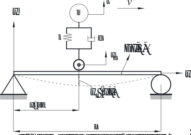
Fig. 1 shows a simply supported Euler-Bernoulli beam and a moving oscillator. Where, m, k, c and y, respectively are oscillator mass, spring constant, damping coefficient and displacement of the oscillator in the vertical direction. The following basic assumptions are discussed before obtaining differential equations of motion of the oscillator:
1. Oscillator proceeds with a constant velocity at a straight path on the beam.
3. Wheel and the sprung mass are making small displacements.
Fig. 1. A single DOF oscillator model and an Euler-Bernoulli bridge beam.
In the system in Fig. 1, the kinetic energy, potential energy, and dissipation function respectively are:
2 2 2
1 1 1
, ( - ) , ( - ) ,
2 2 2
k p c c
E my E k y y D c y y (1)
And the Lagrangian, L=Ek-Ep :
2 2
1
(y y )
2 c
L my k (2)
Lagrange expression for moving oscillator model;
( 1, 2) i
i i i
d L L D
Q i
dx q q q
(3)
Using above expressions the motion equation for moving oscillator itself is as follows
( - c) ( - c) 0
myk y y c y y (4)
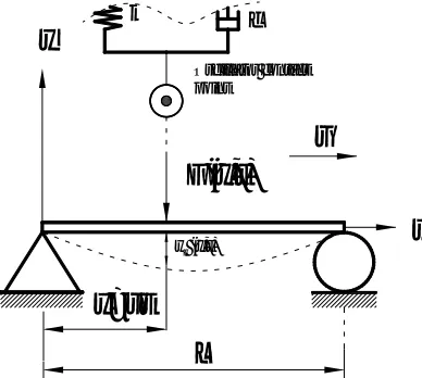
Fig. 2 shows a simply supported Euler Bernoulli beam and a moving oscillator that is moving on the beam with a constant velocity v , where wb(x,t) and F(x,t) respectively are time dependent displacement of the beam and contact force on the beam at position x and time t.
x
y
c
k
y
y
m
w (x,t)
x=vt
L
EI,
,
cFig. 2. An Euler-Bernoulli bridge beam with a moving force.
Motion equation of the beam is given by [1] as follows:
4 2
4 2
(x, t) (x, t) (x, t)
(x, t) (x vt),
b b b
w w w
EI F
t
x t
(5)
In Eq. (5), the expression E represents themodulus of elasticity of the bridge girder, I represents bridge area moment of inertia of beam cross-section, ρ represents mass per unit length of the beam, μ represents the equivalent viscous
damping coefficient for bridge beam girders, and δ represents the Dirac delta function. The time dependent
displacements of the beam at x and time t can be approximated as follows:
1
(x, t) (x) q (t),
N
b k k
k
w
(6)
Whereϕk(x) and qk(t), (k=1,2,..N) are, respectively, represents mode shapes and modal coordinates. Vibration mode shapes of a simply supported beam bridge can be expressed as follows:
2
(x) sin ,
k
k x
L L
p f
r
=
(7)
For any nth modal coordinate, the equation of motin can be expressed as:
2
2 (x vt, t) (x vt)
n n n n n n n
q&&+ V wq&+w q = - F = f = (8)
, 2 n
n
m V
r w
= (9)
2
( ) sin ,
n
n vt vt
L L
p f
r
= (10)
When wheel moves on the bridge, there are two type of displacements: dynamic deformation of the beam and surface
x
y
x=vt
L
v
F(x,t)
c k
w (x,t)
Oscillator contact point
roughness at the contact point of the bridge. In this case, the displacement and and velocity of the wheel contact point is optained as follows:
1
(x, t) r(x) (x) q (t)
N
c b k k
k
y w f r
=
= + =
å
+ (11)1 1
(x) q (t) (x) q (t)
N N
c k k k k
k k
y f f r
= =
=
å
& +å
& +& & (12)
The forces acting on the bridge from wheel are in two type that one is static load of the vehicle and the other is the dynamic load of the vechile. Considering these, the forces acting on bridge from the vehicle at the bridge contact point can be expressed as follows:
( , ) - ( - c) - (t - c),
F x t =W k y y c y& &y (13)
( , ) t t s s,
F x t =W+ m y&&+ m y&& (14)
Imposing the contact forces from Eq. (13) and (14) in Eq. (9), the following motion equations are obtained:
2
2 ,
n n n n n n n t t n s s n
q + l wq&+w q +f dm y&&+f dm y&&= -Wf d (15)
( ) U ( ) U ( ) U Q( ),
M t &&+C t &+ K t = F t (16)
Using Newmark’s integration method [22], the solution of equation (16) can be obtained according to the following steps:
1. Determine the integration parameters β, γ, and magnitude of the time interval Δt. Calculate integration constants:
0 2 1 2 3
4 5 6 7
1 1 1
, , , 1,
2
1, ( 2), (1 ), . 2
a a a a
t t t
t
a a a t a t
(17)
2. Using Eq. (15), define the mass, stiffness and damping[M], [ ]K and [ ]C matrices at tn= (tn-1+ Δt) time.
3. Calculate effective stiffness matrix at (=tn-1+ Δt) time:
0 1
[ ] [ ]K K a M[ ]a C[ ]. (18)
4. Calculate effective force { ( )}F t at time tn (=tn-1+ Δt):
0 1 2 1 3 1 1 1 4 1 5 1
{ ( )}F tn { ( )} [F tn M a U t]( { (n)}a U t{ (n)}a U t{ (n)})+[ ]( { (C a U tn)}a U t{ (n)}a U t{ (n)}).
(19)
5. Calculate deflections at tn time:
1 { ( )} [ ] { ( )}.U tn K F tn
(20)
6. Calculate accelerations and velocities at tn time:
0 1 2 1 3 1
{ ( )}U t n a({ ( )} { (U tn U tn )})a U t{ ( n)}a U t{ ( n)}, (21)
1 6 1 7
{ ( )} { (U t n U t n)}a U t{ ( n)}a U t{ ( )}. n (22)
Steps 3-7, t=tn =tn-1+ Δt (n=1, 2, 3, and t0=0) are repeated for all time steps, for deflections{ (U tn1)}, velocities
{ ( )}U t n and accelerations { ( )}U t n of the entire system.
III.NUMERICALEXAMPLES
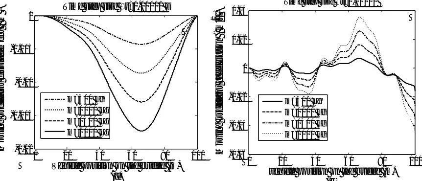
In Table 1, the parameters of the beam and moving oscillator are given. Fig. 3a shows the vertical displacements of the oscillator mass for a integration time step size Δt=0.00001 and for moving velocities of v=11.1, 22.2, 33.3 and 44.4 m/s. The maximum displacement of the oscillator occurs after it has passed the mid-point for v=22.2 m/s. Depending on the velocity and the interaction with the beam, the time and amplitude of the maximums are changed.
Table 1.The numerical values for the oscillator and bridge
Beam Oscillator
L (m) 100 m (kg) 1000 E (Gpa) 207 k(N/m) 3.96x10⁶ I (m4) 0.174 c( Ns/m) 25130
μ (Ns/m2) 0.025 ρ (kg/m) 20000
Fig. 3bpresents accelerations of the oscillator massfor four different velocity of the oscillator. When the velocity of oscillator is increased, it increases the accelerations of the oscillator mass. In addition, maximum acceleration of the oscillator on beam is seized at a distance of about 60-80% of the beam length after the midpoint. While travelling over the beam the point at which maximum acceleration occurs is also affected by the oscillator velocity.
Fig. 3. (a) Oscillator displacement for different velocities v=11.1, 22.2, 33.3, 44.4 m/s, (b) Oscillator acceleration for different velocities v=11.1, 22.2, 33.3, 44.4 m/s.
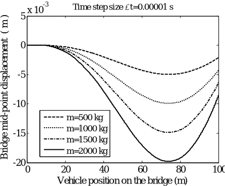
Fig. 4. Bridge mid-point displacement for different oscillator masses m=500, 1000, 1500, 2000 kg.
When the accelerations of the oscillator are concerned, as seen from Fig. 5b, due to the interaction with the beam motion the accelerations of the oscillator are affected by the motion of the beam. The maximum of the accelerations are at about 68 percent of the length of the beam. Any mass increase does not change this behaviour if the motion velocity is constant.
0 20 40 60 80 100
-0.01 -0.008 -0.006 -0.004 -0.002 0
Vehicle position on the bridge (m) (a) M o v in g o sc il la to r d is p la ce m en t ( m
) Time step size t=0.00001 s
11.1 m/s 22.2 m/s 33.3 m/s 44.4 m/s
0 20 40 60 80 100
-0.04 -0.03 -0.02 -0.01 0 0.01 0.02 0.03 0.04
Vehicle position on the bridge (m) (b) M o v in g o sc il la to r ac ce le ra ti o n ( m /s 2 )
Times step size t=0.00001 s,
11.1 m/s 22.2 m/s 33.3 m/s 44.4 m/s
0 20 40 60 80 100
-20 -15 -10 -5 0 5x 10
-3
Vehicle position on the bridge (m)
B ri d g e m id -p o in t d is p la ce m en t ( m )
Time step size t=0.00001 s
Fig. 6. (a) Moving oscillator displacement for different oscillator masses m=500, 1000, 1500, 2000 kg,(b) Moving oscillator acceleration for different oscillator masses m=500, 1000, 1500, 2000 kg
IV.CONCLUTION
In this study, for a moving oscillator and beam interaction the equation of the motion of the whole system is solved using Newmark’s beta method of time integration. Generally, the following results of the interaction may be interesting for vehicle and structural engineers: Due to the interaction the displacements of the oscillator depends upon the moving velocity and the motion of the beam. However, the relation is not linear. For the accelerations of the oscillator mass if the mass is constant, the accelerations linearly increases depending on the velocity. Moreover, for the same travelling velocity of the oscillator, mass increase does not change the behaviour of the interaction if the mass of the oscillator is too small when compared with the mass of the beam. In some applications of heavy transport systems such as overhead cranes and railway bridges, the mass of the oscillator is sometimes maybe very greater than the mass of the beam. In such cases due to the additional mass, the frequency of vibration modes can change nonlinearly while the mass changes its position on the beam.
REFERENCES
1. L. Fryba (1999) Vibration solids and structures under moving loads. Thomas Telford House
2. Bajer CI, Dyniewicz B (2012) Numerical Analysis of Vibrations of Structures under Moving Inertial Load. doi: 10.1007/ 978-3-642-29548-5
3. Lee HP (1996) Transverse vibration of a Timoshenko beam acted on by an accelerating mass. Appl Acoust 47:319–330. doi: 10.1016/0003-682X(95)00067-J
4. Michaltsos G (2002) Dynamic behaviour of a single-span beam subjected to loads moving with variable speeds. J Sound Vib 258:359–372. doi: 10.1006/jsvi.5141
5. Wang Y (2009) The transient dynamics of a moving accelerating / decelerating mass traveling on a periodic-array non-homogeneous composite beam. Eur J Mech A/Solids 28:827–840. doi: 10.1016/j.euromechsol.2009.03.005
6. Esen İ (2013) A new finite element for transverse vibration of rectangular thin plates under a moving mass. Finite Elem Anal Des 66:26–35.
doi: 10.1016/j.finel.2012.11.005
7. Esen I (2011) Dynamic response of a beam due to an accelerating moving mass using moving finite element approximation. Math Comput Appl 16:171–182.
8. Kahya V (2012) Dynamic analysis of laminated composite beams under moving loads using finite element method. Nucl Eng Des 243:41– 48. doi: 10.1016/j.nucengdes.2011.12.015
9. Esen İ (2015) A new FEM procedure for transverse and longitudinal vibration analysis of thin rectangular plates subjected to a variable
velocity moving load along an arbitrary trajectory. Lat Am J Solids Struct 12:808–830.
10. Esen İ, Koç MA (2013) Dynamics of 35 mm anti-aircraft cannon barrel durig firing. In: Int. Symp. Comput. Sci. Eng. Aydın, pp 252–257
0 20 40 60 80 100
-0.02 -0.015 -0.01 -0.005 0
Vehicle position on the bridge (m) (a) M o v in g o sc il la to r d is p la ce m en t ( m
) Time step size t=0.00001 s
m=500 kg m=1000 kg m=1500 kg m=2000 kg
0 20 40 60 80 100
-0.06 -0.04 -0.02 0 0.02 0.04
vehicle position on the bridge (m) (b) M o v in g o sc il la to r ac ce le ra ti o n ( m /s
2 )
Time step size t=0.00001
11. Esen İ, Koç MA (2015) Optimization of a passive vibration absorber for a barrel using the genetic algorithm. Expert Syst Appl 42:894–905. doi: 10.1016/j.eswa.2014.08.038
12. Esen İ, Koç MA (2013) 35 mm Uçaksavar Topu Namlusu için Titreşim Absorberi Tasarımı ve Genetik Algoritma ile Optimizasyonu. In:
Otomatik Kontrol Ulus. Toplantısı-TOK 2013. Malatya, pp 513–518
13. Esen İ, Koç MA (2015) Dynamic response of a 120 mm smoothbore tank barrel during horizontal and inclined firing positions. Lat Am J Solids Struct 12:1462–1486.
14. Fafard M, Bennur M, Savard M (1997) A general multi-axle vehicle model to study the bridge- vehicle interaction. Eng Comput 14:491– 508. doi: 10.1108/02644409710170339
15. Yang YB, Yau JD, Wu YS (2004) Vehicle-Bridge Interaction Dynamics with Applications to High-Speed Railways. World Scientific Publishing Co. Pte. Ltd., Danvers
16. Dugush YA, Eisenberger M (2002) Vibrations of non-uniform continuous beams under moving loads. J os Sound Vib 254:911–926. doi: 10.1006/jsvi.2001.4135
17. Lou P (2005) A vehicle-track-bridge interaction element considering vehicle’s pitching effect. Finite Elem Anal Des 41:397–427. doi: 10.1016/j.finel.2004.07.004
18. Yang YB, Cheng MC, Chang KC (2013) Frequency Variation in Vehicle–Bridge Interaction Systems. Int J Struct Stab Dyn 13:1350019. doi: 10.1142/S0219455413500193
19. Esmailzadeh E, Jalili N (2003) Vehicle–passenger–structure interaction of uniform bridges traversed by moving vehicles. J Sound Vib 260:611–635. doi: 10.1016/S0022-460X(02)00960-4
20. Azimi H, Galal K, Pekau OA (2013) A numerical element for vehicle-bridge interaction analysis of vehicles experiencing sudden deceleration. Eng Struct 49:792–805. doi: 10.1016/j.engstruct.2012.12.031
21. Lou P, Au FTK (2013) Finite element formulae for internal forces of Bernoulli-Euler beams under moving vehicles. J Sound Vib 332:1533–1552. doi: 10.1016/j.jsv.2012.11.011