Selection & Performance Analysis of
Spreading Sequences for DS-CDMA Systems
Darshini M B1, Anupama Shetter2
Assistant Professor, Department of Electronics & Communication Engineering, ATME College of Engineering,
Mysuru, Karnataka, India1
Assistant Professor, Department of Electronics & Communication Engineering, ATME College of Engineering,
Mysuru, Karnataka, India2
ABSTRACT: In CDMA, spread spectrum technology is used where unique code is assigned to each user and allows
multiple users to be multiplexed over the same physical channel. Direct Sequence Code Division Multiple Access (DS-CDMA) wireless transmitter design using FPGA, is a type of spread-spectrum communication system in which multiple signal channels occupy the same frequency band, being distinguished by the use of different spreading codes, which has been adopted in many wireless access technologies. Digital approach is used to design four separate blocks to form the transmitter circuit diagram using the Oscillator, PN-code generator, Parity Check, and BPSK modulator. In the same way at receiver side, the BPSK demodulator is used to recover the original message signal. The Xilinx ISE software and Mentor Graphics software has been used for the design synthesis and simulation and the VHDL program was used for coding. The DS-CDMA wireless transmitter was designed to transmit with data rates up to 2Mbps. The transmitted signals were carried with a 40 MHz carrier frequency.
KEYWORDS:PN Sequence, Multiple access, Spread spectrum, modulator, demodulator.
I. INTRODUCTION
Today spread spectrum communications is the widely used data communication scheme. It has many suitable features to secure, multiple accesses and many other properties that are required in a communication system. Spread spectrum is one of the means of transmission in which the bandwidth will be in excess of the minimum necessary in a signal to send the information. The code is used to achieve the band spread, which is independent of the data and synchronized reception with the code, for dispreading and subsequently data recovery the code at the receiver is used. The transform of an information signal is the purpose of coding which looks almost like noise. Resistance to interference and short range interferences- free overlays on their emissions, from other emissions and detestability are the several possible advantages of spreading or dilution of energy in spread spectrum systems over a wide bandwidth. The low spectral density needed for spread spectrum communication systems as well as ability of some of these systems.
II. SPREAD SPECTRUM MULTIPLE ACCESS
Spread spectrum multiple access (SSMA) uses signals which have a transmission bandwidth and the signal is of several orders of magnitude greater than the minimum required RF bandwidth. Conversion of a narrowband Signal to a wideband noise-like signal is done by a pseudo-noise (PN) sequence before transmission. SSMA provides immunity to multipath interference and robust multiple access capability. When used by a single user, SSMA is not very bandwidth efficient. However, since without interfering with one another, many users can share the same spread spectrum bandwidth. In a multiple user environment, Spread spectrum systems become bandwidth efficient. There are two main types of spread spectrum multiple access techniques; Direct sequence multiple access (DS) and frequency hopped multiple access (FH). Direct sequence multiple access is also called code division multiple access (CDMA).
The bandwidth of the signal can be spread through three types of spread spectrum techniques. They are:
• Frequency Hopping(FH): There will be rapid pseudo-random switching of signals between different frequencies within the hopping bandwidth and at any given time the receiver knows where to find the signal. • Time Hopping (TH): Transmission of the signals takes place in short bursts pseudo-randomly, and the receiver
knows that when to expect the burst, beforehand.
• Direct Sequence (DS): At a much higher frequency, the digital data is directly coded. The pseudo-random code is generated, the receiver knows how to generate the same code, and correlates the received signal with that of code to extract the data.
III.DESIGN OF DIRECT SEQUENCE SPREAD SPECTRUM SYSTEM
Direct Sequence-Spread Spectrum (DS-SS) is one of the transmission technique in which a pseudo-noise code is employed as a modulation waveform to “spread” the signal energy over a bandwidth, independent of the information data, where bandwidth is much greater than the signal information bandwidth. Using a synchronized replica of the pseudo-noise code, de-spreading of the signal is done at the receiver end. In DS-SS, the spreading sequence is often called as PN sequence.
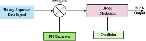
In this section, Binary Phase Shift keying (BPSK) modulation technique is used to modulate the spread signal in the transmitter and BPSK demodulation technique is used to recover the modulated signal on the receiver side. The basic building blocks of DS-SS system are shown in Fig.1.
Fig. 1. Basic building blocks of DS-SS system
IV.PNSEQUENCE GENERATOR
sequence is called as Chip. PN generators are based on Linear Feedback Shift Registers (LFSR). At each clock cycle right shifting of the contents of the registers are done by one position. The feedback from predetermined registers or taps to the left most register is XNOR-ed together.
There are several variables of LFSRs:
• The number of stages in the shift registers • The number of taps in the feedback path
• The position of each tap in the shift registers stage
• The initial starting conditions of the shift registers or “FILL” state.
Fig. 2. Block diagram of PN sequence generator
The duration of the PN sequence before it repeats is as longer as the number of stages of shift registers in the PN generator, longer. For a shift register of fixed length N, the number and position of taps used to generate the parity feedback bit are used to determine the number and duration of the sequences that it can generate.
A maximum length sequence (L) for a shift register of length N is referred to as m-sequence and is defined as:
L = 2N −1 (1)
E.g. an eight stage LFSR will have a set of m-sequences of length 255.
V. DESIGN &IMPLEMENTATION OF DS-CDMATRANSMITTER AND RECEIVER
In DS-SS transmitter, the input data bits are spread by PN sequence generator. The data bits are multiplied with the generated PN sequence code in order to perform spreading. Data signal is lesser than that of the frequency of PN sequence. After spreading, the Data signal is modulated and transmitted. Modulation is done is many several available schemes, viz. M-QAM, BPSK, QPSK, etc. BPSK modulation scheme is the most widely used. In this design, to modulate and transmit the spread signal BPSK modulation is used. The basic building blocks of a simple DS-SS transmitter system are shown in Fig-3.
Fig. 4.Block diagram of a data and PN sequence multiplier
TABLE. 1. Truth table for the multiplier
Multiplier Design Specifications:
• PN sequence Chip rate, Tc = 10 ms. • Data signal Bit rate, Tb > 150 ms.
Let the data signal be m(t) and PN sequence p(t). The two signals are multiplied and the multiplied output is the spread signal. Truth table for the multiplier s(t) = m(t). p(t) is shown in Table-1. From the truth table, it can be inferred that to spread the data signal with the PN signal, an XNOR gate can act as a multiplier. Hence the block diagram for the multiplier is shown in Fig. 4.
In DS-SS receiver, the BPSK modulated signal is the input to the system. This signal would have been affected by noise and other interference in the communication channel. The DS-SS receiver should be designed carefully to reproduce the data signal with least error.
Fig. 6.Block diagram of a DS-SS receiver system
The oscillator multiplies the locally generated carrier wave to the BPSK modulated input signal. To get low frequency components, the multiplied signal is passed through the low pass filter. To approximate the signal to binary sequence, a decision device is used. This binary sequence is the spread sequence of the data signal.
The synchronization of the sequence obtained from the decision device and the locally generated PN sequence is the most sensitive part of the DS-SS receiver. Noise is produced instead of the data signal, when a single bit mismatch occurs. To achieve synchronization and to multiply the locally generated PN sequence code with that of the received PN code, suitable technique is used. After the multiplication process, the Data signal is obtained.
In this design, the delay in the receiver is considered and modelled appropriately, as the transmitter and receiver uses common clock on the same FPGA board.
The block diagram of a simple DS-SS receiver system is shown in Fig-6.
VI.EXPERIMENTAL RESULTS
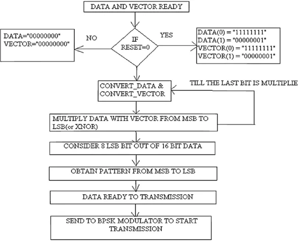
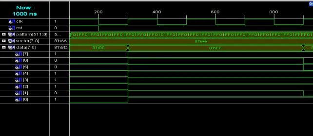
The proposed DS_CDMA is implemented using VHDL, the functionality of the algorithm is verified using Mentor Graphics and synthesized using Xilinx ISE.
Fig. 8. Output of encoding process
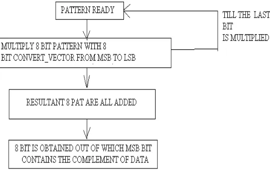
Fig. 9. Output of decoding process
REFERENCES
[1] Chang. K. C.(1997),Digital Design and Modeling with VHDL and Synthesis, IEEE servicecenter, Piscataway.
[2] Sreedevi, B., Vijaya, V., Rekh, C. K., Valupadasu, R., & Chunduri, B. R. (2011, March). FPGA implementation of DSSS-CDMA transmitter and receiver for ADHOC networks. In Computers & Informatics (ISCI), 2011 IEEE Symposium on (pp. 255-260). IEEE. [3] Milstein, Laurence B. "Wideband code division multiple access." IEEE Journal on Selected areas in Communications 18.8 (2000):
1344-1354.
[4] Litvinenko, Anna, and Arturs Aboltins. "Selection and performance analysis of chaotic spreading sequences for DS-CDMA systems." Advances in Wireless and Optical Communications (RTUWO), 2016. IEEE, 2016.
[5] Moshavi, Shimon. "Multi-user detection for DS-CDMA communications." IEEE communications magazine 34.10 (1996): 124-136. [6] Cheah,J.,Y,C.,Practical Wireless Data Modem Design, Artech House Publishers, Boston, London,1999.
[7] Feher,K.(1995),Wireless Digital Communications, PrenticeHall,Inc., Upper Saddle River, New Jersey.
[10] Jakes,W.C.,Jr.(1994), Microwave Mobile Communications, J.Wiley & Sons, NewYork, 1974; IEEEPress, 1994, ISBN0-7803-1069- [11] Oianpera, T.,Prasad, R., Wideband CDMA for Third Generation Mobile Communications, Artech House Publishers, Boston, London, 1998. [12] Rushton,A., VHDL for LogicSynthesis, JohnWiley & SonsLtd,Chichester, England,1998.