Ann Based Control Strategy for Parallel
Operation of Single Phase Voltage Source
Inverter
Sriram S
1, Manikandan P
2Assistant Professor, Head of Department, Dept. of EEE, Sasurie College of Engineering, Tirupur, Tamilnadu, India1
Assistant Professor, Dept. of EEE, Sasurie College of Engineering, Tirupur, Tamilnadu, India2
ABSTRACT:This paper describes about the efficient control strategy in parallel operation of inverters in common alternatingcurrent(AC) bus which is used in real time applications like uninterrupted power supply (UPS), medical equipments and many. The control system for parallel operation of inverters consists of two main loops; the first control loop is parallelism control over the feedback inductor current to modify the input voltage to the filter. The second loop is voltage control over the output voltage of each individual voltage source inverter connected to the common AC bus. Here control system is implemented in neuro fuzzy control strategy which ensures less precise, flexible, better stability in control. The proposed control strategy ensures the voltage source inverters(VSI) operating in common AC bus with proper sharing of load current, redundancy and without any needs of communication exchange between inverter modules .The parallel operation of inverters in common AC bus with proposed control system are verified both in theoretical and experimental results.
KEYWORDS: Alternating Current(AC),Uninterrupted Power Supply(UPS),Voltage Source Inverters(VSI),Direct Current (Dc),Average Load Sharing(ALS),Master Slave(MS)
I. INTRODUCTION
The need for highly reliable power supplies has increased in recent years with the proliferation of critical loads such as computers,medical equipments, satellite systems, telecommunications, and other electronic dependent equipment, which are intensely in demandin present day society. Not with standing, the role of uninterruptible power supply (UPS) has also increased tremendously in
sustaining high reliable power to those critical loads. One of the ways to achieve higher reliability is by paralleling two or more unitsof UPS. This is because the paralleled system has wide advantages over single unit UPS. Advantages include increase of powercapability, enhanced availability from the fault tolerance with more than 1 module, and ease of maintenance with redundancy
II. THE CONCEPTION OF CONTROL STRATEGY
The control strategy includes two main loops for each voltage source inverters (VSI) connected to common AC bus. They areParallelism control loop and voltage control loop. The parallelism control loop employs the feedback of the inductor current from theoutput filter to modify the input voltage of the same filter and, therefore, to control the power flow of each inverter to the load. The second loop voltage control is responsible for controlling the output voltage of the LC filter, which coincides with the output voltage
In each VSI, a control loop is added, called parallelism control, which is placed in cascade with the voltage controller Cv, as shownin Fig. 1. This second loop enables the inverter to work in parallel. This new control modifies the output signal of the voltagecontroller, Vvc, with the aim of changing the Vpcsignal applied in the PWM modulator and, consequently, altering the VAB voltage of
the VSI. The parallelism control employs the feedback of inductor current L from the LC filter, called Vi, to modify the Vvcsignal.Therefore, each VSI utilizes only the feedback of its own inductor current to ensure its proper parallel operation. A relevant point isthat the proposed strategy is based on a single reference voltage (Vref) for all VSIs, thus the output voltages of all inverters have only
small deviations, which are caused by parametric variations in the control and power Fig.1. Circuit of a VSI based on the proposedcontrol strategy. Components of the inverters. Therefore, the parallelism control has the function of equalizing these small deviationsto ensure power sharing among the inverters [3].
Proposed Control Strategy
We consider a multi-input, single-output dynamic system whose states at any instant can be defined by ―n‖ variables X1, X2, Xn.The control action that derives the system to a desired state can be described by a well known concept of ―if-then‖ rules, where inputvariables are first transformed into their respective linguistic variables, also called fuzzification [4],[5]. Then, conjunction of theserules, called inferencing process, determines the linguistic value for the output. This linguistic value of the output also called fuzzifiedoutput is then converted to a crisp value by using defuzzification scheme. All rules in this architecture are evaluated in parallel togenerate the final output fuzzy set, which is then defuzzified to get the crisp output value. The conjunction of fuzzified inputs isusually done by either min or product operation (we use product operation) and for generating the output max or sum operation isgenerally used. For defuzzification, we have used simplified reasoning method, also known as modified center of area method. Forsimplicity, triangular fuzzy sets will be used for both input and output. The whole working and analysis of fuzzy controller isdependent on the following constraints on fuzzification, defuzzification and the knowledge base of an FLC, which give a linearapproximation of most FLC implementations [6].
CONSTRAINT 1: The fuzzification process uses the triangular membership function.
membership values over theuniverse of discourse at any instant for a control variable will always be equal to one. This constraint is commonly referred to as fuzzypartitioning.
CONSTRAINT 3: The defuzzification method used is the modified center of area method. This method is similar to obtaining aweighted average of all possible output values.
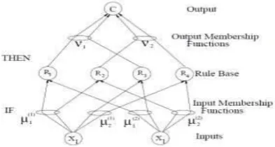
An example of a very simple neuro fuzzy controller with just four rules is depicted in figure 2. This architecture can be readilyunderstood as a ―neural-like‖ architecture. At the same time, it can be easily interpreted as a fuzzy logic controller. The modules X1and X2 represent the input variables that describe the state of the system to be controlled. These modules deliver crisp input values tothe respective membership modules (m-modules) which contain definitions of membership functions and basically fuzzify the input.Now, both the inputs are in the form of linguistic variables and membership associated with the respective linguistic variables. The mmodulesare further connected to R-modules which represent the rule base of the controller, also known as the knowledge base. Each
m-module gives to its connected R-modules, the membership value m (xi) of the input variable Xi associated with that particularlinguistic variable or the input fuzzy set. The R-modules use either min-operation or product-operation to generate conjunction of theirrespective inputs and pass this calculated value forward to one of modules. The n-modules basically represent the output fuzzy sets or store the definition of output linguistic variables. If there are more than two rules affecting one output variable then either their sumor the max is taken and the fuzzy set is either clipped or multiplied by that resultant value. These n-modules pass on the changedoutput fuzzy sets to C-module where the defuzzification process is used to get the final crisp value of the output .
Fig 2. Architecture of four rule fuzzy controller from neural networks point of viewThe X-, R-, and C-modules
can be viewed as the neurons in a layered neural network and the and n-units as the adaptable weights of thenetwork. The X-modulelayer can easily be identified as the input layer of a multi-input neural network whereas the C-module layer can be seen as the outputlayer. The R-module layer serves as the hidden or intermediate layer that constitutes the internal representation of the network. Thefact that one n-module can be connected to more than one R-module is equivalent to the connections in a neural network that share acommon weight. This is of key importance for keeping the structural integrity of the fuzzy controller intact.
III. EXPERIMENTAL ANALYSIS
Fig 3. Circuit of VSIs modules connected in parallel
This methodology defines voltage and current equations for each inverter in relation to the components of all VSI. Thus, the modelallows the study of the distribution of power, sharing, and circulation of currents among inverters in the case of parametric variation ofthe components, load variations, and controller modifications. The specification for two voltage source inverters connected in parallel
in common AC bus shown in block representation in fig 3.are detailed in TABLE I
IV. SIMULATION RESULTS
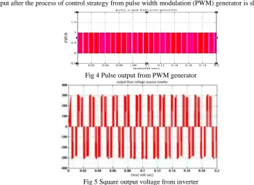
Pulse output after the process of control strategy from pulse width modulation (PWM) generator is shown in fig 4
Fig 4 Pulse output from PWM generator
Fig 5 Square output voltage from inverter
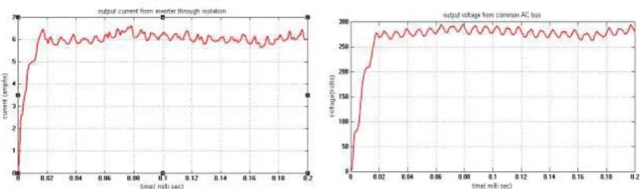
Fig 6.Output current measured from the inverter Fig 7.Output voltage measured from common AC bus
V. CONCLUSION
Thus the uninterrupted power supplies (UPS) and medical equipments frequently needs parallel operation of inverters with proper loadsharing capability and redundancy. Hence proper control strategy should be implemented for independent operation of voltage sourceinverters making them to work at any load conditions and no load conditions. The control strategy allows the connection and/ordisconnection of one inverter from the common ac bus with a smooth transient response in load voltage. It also enables the parallel operationof different power inverters. ANN control strategy which emerging control logic for many application is more efficient and satisfies allfeatures of control strategies of parallel operation of voltage source inverters. Simulation results have shown that fast dynamic response,proper output regulation, and equal current distribution can be achieved in the proposed multi-module inverter system.
REFERENCES
[1] YeongJia.C and E. K. K. Sng, ―A novel communication strategy for decentralized control of paralleled multi-invertersystems,‖ IEEE Trans. Power Electron., vol. 21, no. 1, pp. 148–156, Jan. 2006.
[2] Guerrero J.M, L. Hang, and J. Uceda, ―Control of distributed uninterruptible power supply systems,‖ IEEE Trans. Ind.Electron., vol. 55, no. 8, pp. 2845–2859, Aug. 2008.
[3] Telles B. Lazzarin, Member, IEEE, Guilherme A. T. Bauer, and Ivo Barbi, ―A Control Strategy for Parallel Operation ofSingle-Phase Voltage Source Inverters: Analysis,Design and Experimental Results‖IEEE transactions on industrial
electronics, vol. 60, no. 6, june 2013.
[4] Comparison between Conventional PID and Fuzzy Logic Controller for Liquid Flow Control: Performance Evaluation ofFuzzy Logic and PID Controller by Using MATLAB/Simulink Gaurav, AmritKaur,june 2012
[5] Zhongyi.H and X. Yan, ―Distributed control for UPS modules in parallel operation with RMS voltage regulation,‖ IEEETrans. Ind. Electron., vol. 5, no. 8, pp. 2860–2869, Aug. 2008.
[6] Qing-Chang Zhong, Senior Member, IEEE,‖Robust Droop Controller for Accurate Proportional Load Sharing AmongInverters Operated in Parallel‖IEEE transactions on industrial electronics, vol. 60, no. 4, april 2013