Research Development Cell, Government College of Engineering, Jalagon (M. S), India
Ball Bearing Stacking System
Shafeequerrahman S Ahmed1, Prof.Suresh Annadate2
PG Student, Department of Electronics Engineering, Jawaharlal Nehru Engineering College, Auranagabad, Maharashtra, India1
Associate Professor, Department of Electronics Engineering, Jawaharlal Nehru Engineering College, Auranagabad, Maharashtra, India2
ABSTRACT:This document is an effort to introduce the concept of automation in small scale industries and or small workshops that are involved in the manufacturing of small objects such as nuts, bolts and ball bearing in this case. This an electromechanical system which includes certain mechanical parts that involves one base stand on which one vertical metallic frame is mounted and hinged to this vertical stand is an in humanized effort seems inadequate in this era making necessary the use of Electronics, Computer in the manufacturing processes leading to the concept of Automated Manufacturing System (AMS).The ball bearing stack automation is an effort in this regard.
In our project we go for stack automation for any object for example a ball bearing, be that is still a manual system there. It will be microcontroller based project control system equipped with microcontroller 89C51 from any manufacturer like Atmel or Philips. This could have been easily implemented if a PLC could be used for manufacturing the staking unit but I adopted the microcontroller based system so that some more modification in the system can be effected at will as to use the same hardware .Although a very small object i.e. ball bearig or small nut and fixture will be tried to be stacked, the system with more precision and more power handling capacity could be built.for various requirements of the industry. For increasing more control capacity, we can use another module of this series. When the bearing is ready , it will be sent for packing. This is sensed by an inductive sensor. the output will be proceeds by PLC and microcontroller card which will be driving the assembly in order to put it into pads or flaps.
This project will also count the total number of bearings to be packed and will display it on a LCD for real time reference and a provision is made using a higher level language using hyper terminal of the computer.
KEYWORDS: concept of automation, carriage assembly ,proximitysensor,solenoid valve microcontroller and its action,comm. port ,assembly language programming,VB.0assembly language and finally interfacing of the carriage assembly with the computer.
I. INTRODUCTION
Automation focuses on the use of control systems (such as numerical control, programmable logic control, and other industrial control systems), in associationwith other applications of information technology (such as computer-aided technologies [CAD, CAM, CAX] to control industrial machinery and processes, reducing the need for humanbeing’s cumbersome efforts. In the scope of industrialization, automation is a step beyond mechanization. Whereas mechanization provided human operators with machinery to assist them with the muscular requirements of work, automation greatly reduces the need for human sensory and mental requirements as well. Processes and systems can also be automated.
Automation plays a vitalrole in maintaining the global economy and in daily experience. Engineers strive to combine automated devices with mathematical and organizational tools or models to create complex systems for a rapidly expanding range of applications.
Research Development Cell, Government College of Engineering, Jalagon (M. S), India
tasks is possible.
Specialized hardened computers, referred to as programmable logic controllers (PLCs), are frequently used to synchronize the flow of inputs from (physical)sensors and events with the flow of outputs to actuators and events. This leads to precisely controlled actions that permit a tight control of almost any industrial process.
Human-machine interfaces (HMI) or computer human interfaces (CHI), formerly known as man-machine interfaces, are usually employed to communicate with PLCs and other computers, such as entering and monitoring temperatures or pressures for further automated control or emergency response. Service personnel who monitor and control these interfaces are often referred to as stationary engineers.
II. RELATEDWORK
The main objective of this project is to stack the objects coming at the outlet of any manufacturing unit in this case I have taken the example of ball bearing that are available at the outlet of say a bearing manufacturing machine. Initially the tray in which the bearings are to be tacked is kept at a predefined reference level either in X or Y direction. The first object will be put at the reference position. It will be counted and the display will show reading 1.Proper time delay will be given until the next bearing comes. No sooner the next bearing comes at the outlet of the machine, the tray is kept in the same position. The movement of the tray either in X direction or in the Y direction should start only when the arrival of new object is sensed with the help of proper sensor. Not with human hand. So, that the inductive sensors is used to detect the only the Metal so that the shift in the reference position can be initiated.
Research Development Cell, Government College of Engineering, Jalagon (M. S), India
III SYSTEM DESIGN
A. THE INDUCTIVE PROXIMITY SENSOR
Fig 3.1 proximity sensor working
operating principle is based on a coil and oscillator that creates an electromagnetic field in the close surroundings of the sensing surface.
When the detecting distance is one inch or less and your application calls for metal sensing, the inductive proximity sensor provides the needed sensing solution. The inductive proximity sensor[2] choice seems natural due to its rugged metal housing and enclosed internal circuitry. The proximity sensors epoxy potting makes the inductive device superior to other sensing technologies when the environment is harsh like those found in machine tool sensor applications where dust and dirt build up are an issue. Additionally, the inductive proximity sensor is currently the best selling sensing technology worldwide, so you know that it has been well proven.
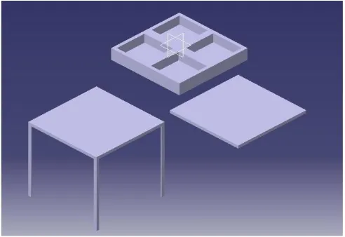
Fig 3.2:Conceptual Primitive design of flap or tray
The above figure shows the various parts made from mild steel that will be suitably assembled in order to form the carriage assembly. Suitable machining and fabrication techniques [9] have been applied. Proper utilization of welding
BN
BK
BU
Note
:
Research Development Cell, Government College of Engineering, Jalagon (M. S), India
enough strengthcould be provided in order to withstand the power delivered by the pneumatic cylinders. It shows a conceptual view of the various parts of the carriage assembly.
Fig.3.3The actual photograph of carriage assembly
However a typical assembly is also there which is shown in the above figure. The two pneumatic cylinders are also shown and the inclined bar is the guided path through which the bearing or the object manufactured is guided down to the reference position of the carriage assembly’s tray
The materials chosen for the above mentioned automated or semi automated assembly depends upon object to be sensed. Cylinder thrust is also a key factor.
C.THE PNEUMATIC CYLINDER
The pneumatic cylinder deployed here is a double acting cylinder[2]. It works on air as the air is most common medium for displacement operations. The bore diameter is around 25mm and the distance to be moved is in between 80mm to 100mm . The figure shown below sketches the assemble part of compressed air supply to the pneumatic cylinder. Also for regulated air flow , flow control valves can be used .
Research Development Cell, Government College of Engineering, Jalagon (M. S), India
The thrust generated by a double acting cylinder is given by
= ( ×
× )/4
Where
F is cylinder thrust in Kg
D is the diameter of the piston in cm And P is operating Pressure in “Bar”.
TABLEI
PNEUMATIC CYLINDER ‘S VARIOUS PARAMETERS
Sr. No Inlet Pressure
Compression Factor
M Constant
1 1 2.0 0.092
2 2 3.0 0.062
3 3 4.0 0.062
4 4 5.1 0.054
5 5 6.0 0.049
D. THE SOLENOID VALVE
A solenoid valve is an electromechanical device used for controlling liquid or gas flow[1]. The solenoid valve is controlled by electrical current, which is flowing through a coil. When the coil is energized, a magnetic field is created, causing a plunger inside the coil to move. Depending on the design of the valve, the plunger will either open or close the valve. When electrical current is removed from the coil, the valve will return to its de-energized state.In direct-acting solenoid valves, the plunger directly opens and closes an orifice inside the valve. In pilot-operated valves (also called the servo-type), the plunger opens and closes a pilot orifice. The inletline pressure, which is led through the pilot orifice, opens and closes the valve seal. The most common solenoid valve has two ports: an inlet port and an outlet port. Advanced designs may have three or more ports.Some designs utilize a manifold-type design. Solenoid valves make automation of fluid and gas control possible. Modern solenoid valves offer fast operation, high reliability, long service life, and compact design. Also to regulate smooth movement of the pneumatic cylinder , the flow control valve have been utilized so that the burst strike could be transformed into uniform motion and as result the overall assembly could be guarded and is safe to the damages caused by the power strokes of pneumatic cylinders. the flow control valve is deployed.
Solenoid valve coils are available for both DC and AC electricity. Although a coil can be made to work with almost any imaginable voltage, the most common voltages available are 6 to 24 volt DC as well as 24 volt AC and 120 volt and even upto 220/240 voltAC.
The connector standard used for solenoid valves is DIN 43650 . The DIN 43650 series consists of five connectors, which have the following pin spacing:
DIN 43650 Form A - 18 mm
Industrial Form B - 11 mm
DIN 43650 Form B - 10 mm
DIN 43650 Form C - 8 mm
Micro-Mini - 9.4 mm
The Microcontroller System
Research Development Cell, Government College of Engineering, Jalagon (M. S), India
The resourcesof the microcontroller have been effectively.Appropriate registers have been programmed and flags are also set or cleared at optimum conditions.
This is a port of computer. The MSComm. control provides you with convenient access to your PC's serial ports. You can set the port number, baud rate, parity, and the number of data bits and stop bits and can open the port and send or receive data. Generally serial communication is deployed. A PC's BIOS usually allows up to four serial ports, called COM1 through COM4, even though fewer may actually be installed, and this must be morritored by the MSCommunication control. In addition, there can be only one instance of any of the ports at any given time, since two programs or devices cannot use the same port at the same time. When using the MSCOMM [7] control to send and receive serial data, it is best to use event driven communications. This method is more efficient than polling, as it uses less CPU time and will only initiate an action when input is received. The entire electromechanical assembly is connected to the PC using proper and suitable interfacing technique.
A Parallel interface [6] is introduced in between desktop computer and carriage assembly machine and leak test machine. As soon as scanning of bar code is complete the programmed software makes leaks test machine on by sending signal on parallel port. Also if the test is successful then a signal to make marking machine on is sent on the different port of parallel interface. The result of leak test machine (passed or failed) is given to software via serial port [6]
Earlier procedure of the ball bearing automation that is tracking uses a simple notebook which consists of manual entry of time of shift, employee identification, and predefined number of stake, time of work. For data logging of number of bearings available tested, number of attempts made etc for all these software is developed in Visual Basic 6.0 [4] which provides an integrated development environment.It share the systems data in terms of numeric data types. As VB.6.0[5] is an event driven programming language. It produces result in excel sheet for a particular shift or for a date or even the employees could be assigned a login and their record can be maintained. This is convenient for the industrial application. Visual Basic 6.0 [6] provides various graphical user interface for good visualization.
IV. EXPERIMENTAL RESULT
As soon as the standard pressure air at the in let of pneumatic cylinder is maintained, and the stacking cycle is initiated, the flap or tray in which the object is being stacked is moved in response to the actuation triggered by the inductive proximity sensor to the position where the object is expected to come
V.
C
ONCLUSIONBy the advent of this process, production efficiency can be increased to a great extent. It takes 30 second for an engine testing, and because of the use of advanced and sophisticated equipments and software reliability can be guaranteed. The idea so far described throughout the discussion of the project aims to increase the efficiency of labor and record keeping
REFERENCES
[1] www.solenoid-valve-info.com [2] http://en.wikipedia.org/wiki/Sensoro
[3] The 8051 Microcontroller And Embedded System Using Assembly And C, 2/E [4] www.atmel.com
[5] Ed Robinson Michael Bond and Ian Oliver” Upgrading Microsoft Visual Basic 6 to Microsoft Visual Basic.NET”. [6] Lou Tylee “Microsoft Visual basic 6.0”.
[7] Steven Holzner “Visual Basic 6 Black Book”, Publisher: The Coriolis Group.
[8] Jean Andrews “A Guide to Managing and Maintaining Your PC,Cengage Learning 2009. [9] Frank Marlow, PE,”Welding fabrication and repair