ISSN (Print) : 2347 - 6710
I
nternationalJ
ournal ofI
nnovativeR
esearch inS
cience,E
ngineering andT
echnology Volume 3, Special Issue 3, March 20142014 International Conference on Innovations in Engineering and Technology (ICIET’14)
On 21st & 22nd March Organized by
K.L.N. College of Engineering, Madurai, Tamil Nadu, India
ABSTRACT—In the recent days, power demand is more than the generation due to huge loads. Hence it is difficult to operate the power system in order to maintain stable power supply. It will lead to major problems like voltage instability and power losses. To overcome these problems, Flexible AC Transmission System (FACTS) have been implemented in power system. Effective results can be obtained by placing these devices in suitable location. In this paper, the location and the ratings of FACTS devices are optimized using Genetic Algorithm (GA). The main objective is to optimize the location and ratings of FACTS devices by considering the three objectives such as the
minimization of Voltage Stability Index (VSI),
minimization of power losses and minimization of generation cost. Thyristor controlled series capacitor (TCSC) and Static VAR Compensator (SVC) are considered for this project. Genetic Algorithm (GA) is a an iterative method used to provide an optimal solution by solving multi objective optimization problems. The locations and ratings of SVC and TCSC are optimized in IEEE 14 bus and IEEE 30 bus systems using GA. Simulations are done by using MATLAB software. It is clear from the results that the voltage stability is enhanced well and also there is a reduction in power loss by GA when compared with the conventional method.
KEYWORDS— voltage stability index; SVC; TCSC; GA.
I. INTRODUCTION
Due to increase in power demand, many power systems
are generated and are widely interconnected. As the power transfer grow, it is more complex to maintain voltage at all buses in the power system. Due to some of the reasons like the generating station is locating far away from the load centre, inability to meet the reactive power demand, sudden system condition will lead to voltage instability and losses. Introduction of FACTS devices in suitable location will provide power flow control, reactive power demand, etc. Conventional methods are not suited for multiobjective optimization. Out of many EA techinques GA is used for optimizing the locations of SVC and TCSC because GA is efficient than the conventional method. It can able to provide optimal solution by iterations using genetic operators. Reactive power demand is the main cause for voltage instability as in [1]. The voltage magnitude, phase angle and line impedance of the transmission line as in [2] and [3]. FACTS devices can able to provide control flow, enhance voltage profile as in [4]. FACTS devices are able to enhance the performance of power system as in [5]. FACTS devices can be optimally located by GA and thus voltage stability and static security margin can be increased as in [6]. GA can be optimize the location, type and the rated value of the devices as in [7]. SVC is optimally located by GA with Particle Swarm Optimization to reduce the generation cost and to increase the power transfer capacity which proves that
Enhancement of Voltage Stability by SVC
and TCSC Using Genetic Algorithm
S.K.Dheebika, Dr.R.Kalaivani
Department of Electrical And Electronics Engineering, Rajalakshmi Engineering College
Affliated to Anna University, Thandalam, Chennai. India.
Department of Electrical And Electronics Engineering, Rajalakshmi Engineering College
GA is efficient with other algorithm as in [8]. Multitype FACTS devices are optimally located to reduce losses and to increase the security margin by GA as in [9]. FACTS devices are used to solve the optimal power flow problems by placing it in an optimal location as in [10], [11], [12] and [14]. TCSC can able to do congestion management when their location and ratings are optimized as in [15] and [18]. The location and ratings of FACTS devices were optimized by GA and the system loadability and minimization of power losses as in [17]. The location and the control variable settings of TCSC are optimized and the system performance was enhanced and the powerflow in a transmission line was improved as in [19]. From the overview of literature survey, it is clear that FACTS devices has provided versatile benefits and the system performance can be improved drastically when compared without FACTS devices in the system. This paper gives the application of GA to find the location and ratings of TCSC and SVC optimally to enhance the voltage stability, reduce the power losses and the generation cost than the conventional methods.
II.PROBLEM FORMULATION
A multi-objective optimization problem consists of multiple objective functions with equality and inequality constraints to be optimized. The equality constraints represents the typical load flow equations. The inequality constraints represent the operating limits of the TCSC and SVC. Here, a problem with three objective functions is formulated which include the minimization of VSI, minimization of real power loss and minimization of generation cost. Better results can be obtained by minimizing all the objective function and to satisfy all the constraints.
A.Voltage stability index, F1 (Constant)
Voltage stability is an important problem to power system. Voltage stability is evaluated at each bus of the system by an indicator, L - index. At load bus j, L - index can be expressed as given in (1).
jεαL
where
αL - set of load buses
αG - set of generator buses
Vj - complex voltage at load bus j
Vi - complex voltage at generator bus i
Cij - Elements of matrix C which can be determined
using (2)
[C] = -[YLL]-1[YLG] (2)
Sub matrices of Y bus matrix are [YLL] and [YLG] and it
can be found using (3).
I
LI
G=
Y
LLY
LGY
GLY
GGV
LV
G(3)
The first objective function considering the
minimization of Voltage Stability Index can be represented as given in (4).
F1 = Voltage Stability Index = Lmax
B. Power loss, F2 (MW)
The second objective function considering the minimization of real power loss can be expressed as given in (5).
(5)
Where
Vi - the voltage magnitude at bus
gi,j - the conductance of line i-j
δi - the voltage angle at bus i
NL- the total number of transmission lines
C. Fuel Cost of generators, F3($/MWhr)
The third objective function considering minimization of cost of generation can be represented as given in (6).
F3=min F(Pn) = (6)
where
n - the number of generators
PGi - generated power of ith generator
ai - Cost coefficient of ith generator ($/MWh2)
bi - Cost coefficient of ith generator ($/MWh)
ci - Cost coefficient of ith generator
D. Fitness function
Considering all the three objective functions from (1)-(6) the Fitness Function (FF) is expressed as given in (7).
Fitness function,F =h1F1+h2F2 + h3 F3
(7)
where h1, h2 and h3 are weighting factor of
minimization of VSI objective function, weighting factor of power loss minimization objective function, weighting factor of generation cost minimization objective function.
h1+h2+h3=1
(8)
where h1, h2 and h3 are coefficients. By trial and error
method, they are optimized to 0.3, 0.3 and 0.4 for SVC and 0.35, 0.35,0.3 for TCSC by satisfying (8).
III. FACTS DEVICE
A. Power flow modelling of SVC
A shunt connected device, SVC which consists of a Thyristor Controlled Rectifier (TCR) in parallel with a bank of capacitor. It regulates the voltage magnitude at which it is connected by either generating or absorbing the reactive power. It is mainly used to provide fast reactive power and voltage regulation support. The basic SVC model is shown in Fig 1.
Fig 1. Basic model of SVC
The current drawn by the SVC is given in (9).
ISVC = jBSVCVk (9)
where BSVC is the susceptance of SVC and Vk is the
voltage at bus k.
The active and reactive power flow equations of SVC is given in (10) and (11).
(10)
QGi − QDi = Vi [Vk[Giksin(θi−θk) + Bikcos(θi−θk)]] n
k=1
(11)
Where Gik is the conductance and the susceptance Bik
are between bus i and j respectively.
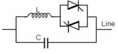
B. Power flow modelling of TCSC
TCSC is a series connected FACTS device in which a capacitor is connected in series with the transmission line and a parallel connection of thyristor-controlled inductor with the capacitor. The power flows in heavily loaded line can be reduced by TCSC through power flow control in the network.
Fig 2.Basic model of TCSC
The rated value of TCSC where the it is located is given by (12).
X ij= X Line+ X TCSC (12)
where XLine- the reactance of the transmission line.
The power flow equations of TCSC are as given by (13) and (14)
Pij=Vi2gij-ViVj (gijcosij+bijsinij) (13)
Qij=Vi2bij-ViVj (gijsinij+bijcosij) (14)
Where Vi and Vj are voltages of ith and jth bus respectively.
IV. GENETIC ALGORITHM
GA is a search heuristic method based on the Darwinian theory of the fittest which was developed by John Holland in 1970. It is an iterative procedure used to provide optimal solutions by solving multiobjective optimization problems.
At each step of iteration, the individuals are selected randomly from the current population to be parents and the next generation is formed by those parents. Optimal solution can be obtained in repeated iterations. GA can be used to solve to optimization problems with a variety of objective functions even it is highly non-linear, nondifferentiable or discontinuous,. New generation can be obtained through the genetic operators.
COMPONENTS OF GA
The major components of GA are required to create the new generation from the current population as follows:
a) Initial population
GA starts with a large group of randomly selected chromosomes knows as initial population. The initial population is created by using the following parameters:
NFACTS, Nlocation, Ntypes represents the the number of
FACTS devices, the possible location of the devices, the types of devices respectively.
b) Selection
Selection selects the parents with high fitness from the current population and insert them in a mating pool to create new offsprings. Some of the selection procedures are stochastic, uniform, remainder, roulette wheel, Tournament, rank selection, steady state selection, etc.
c) Crossover
Crossover plays a major role in convergence speed of GA. After selecting the parents with higher fitness, select an appropriate site to perform recombination process and the contents to the right of the site is exchanged. Some of the crossover schemes are scattered, Intermediate, arithmetic, single point, multipoint or uniform crossover have been used.
c) Mutation
Mutation operator prevents the premature stopping of the algorithm. It changes a random bit value in a chosen string involves flipping it, changing 0 to 1 and vice versa with a low probability. Gaussian, uniform, adaptive feasible are some of the options of mutations. Mutation probability specifies how often parts of chromosomes will be mutated.
A. STEPS IN GA
SVC and TCSC are to be placed in IEEE 14 bus and IEEE 30 bus systems by GA, the following steps are to be followed :
Step 1: Initially create a population
(NFACTS,Ntype,Nlocation, Nrated,Nind)
Step 3: For all the individuals fitnesss values are evaluated.
Step 4: Based on the fitness values, a new population has been selected from the old population based on the evaluation function as given.
Step5: Genetic operators (crossover and mutation) applied to the population that has been selected to create new solutions.
Step6: Fitness value is evaluated for new chromosomes and use them into the population.
Step7: If it exceeds the time, stop the process and provide the best Individual if not, proceed from step 4.
V.RESULTS AND DISCUSSION
IEEE 14 bus and IEEE 30 bus systems was used for the tests by GA and the results were obtained. In which the location and ratings of SVC and TCSC were optimized and the objectives such as VSI, power losses and generation cost were minimized. The parameters used by GA is shown in TABLE I. This proves that the GA is more efficient than the conventional method.
TABLE I
GA PARAMETERS
Population 20
Crossover fraction 0.8
Selection function Stochastic uniform
Elite count 2
Crossover function Scattered
A. IEEE 14 BUS SYSTEM
IEEE 14 bus system consists of five generator buses
(bus no.1,2,3,6 and8), nine load buses (bus
no.4,5,7,9,10,11,12,13 and 14) and 20 transmission lines.
1.Optimal location and rating of SVC and TCSC in IEEE 14 bus system
For each chromosome in the population, location of SVC and TCSC device is initialized. Fitness function evaluated for each chromosome considering minimization of voltage stability index, the total real power loss and minimization of the cost of generation.The optimal location of SVC in IEEE 14 system is identified as 10 and susceptance rating is optimized as 0.0086 p.u. by GA by considering all the three mentioned objection. The optimal location of TCSC in IEEE 14 system is identified as line 17 using GA by considering all the objective functions. Hence TCSC is placed between bus number 9 and bus number 14.
B. IEEE 30 BUS SYSTEM
IEEE 30 bus system consists of six generator buses (bus no. 1, 2, 5, 8, 11,and 13), 24 load buses (bus no. 3, 4, 6, 7, 9, 10, 12, 14 ,15, 16, 17, 18, 19, 20, 21, 22,
23, 24, 25, 26, 27, 28, 29 and 30) and 41 transmission lines.
1.Optimal location and rating of SVC and TCSC in IEEE 30 bus system
The optimal location of SVC in IEEE 14 system is identified as 24 and susceptance rating is optimized as 0.0692 p.u. by GA by considering all the three mentioned objectives. The optimal location of TCSC in IEEE 30 system is identified as line 36 using GA by considering all the objective functions. Hence TCSC is placed between bus number 28 and bus number 27.
A. COMPARISON OF VOLTAGE Profile in
IEEE 14 BUS AND IEEE 30 BUS SYSTEMS
The enhancement of voltage stability in IEEE 14 bus system is shown in Fig 2. It is observed that voltage profile by GA is enhanced well when compared with the conventional method.
Fig 2. comparison of voltage profile in IEEE 14 bus System
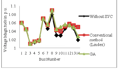
The enhancement of voltage stability in IEEE 30 bus systemis shown in Fig 3. The voltage magnitude is increased at all buses of IEEE 30.bus system.
Fig 3. comparison of voltage profile in IEEE 30 bus system
A. COMPARISON OF OBJECTIVE
FUNCTIONS IN IEEE 14 BUS SYSTEM
Fig 4. Comparison of VSI
When SVC and TCSC placed by GA, power loss is reduced by 0.15 MW and 1.6082 MW respectively and fuel cost is reduced by 0.5908 $/MWhr and 0.5228 $/MWhr. It proves that GA is more efficient in minimizing the objective functions when compared with the conventional method.
Fig 5. Comparison of real power loss
Fig 6. Comparison of generation cost
A. COMPARISON OF OBJECTIVE
FUNCTIONS IN IEEE 30 BUS SYSTEM
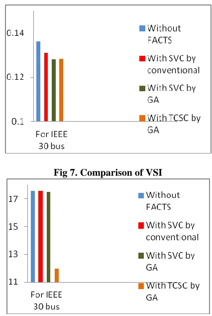
The comparison of minimization of VSI, Power loss and generation cost are shown in Fig 7 - Fig 9. When SVC and TCSC placed by GA, power loss is reduced by 0.057 MW and 5.5862 MW respectively and fuel cost is reduced by 0.2254 $/MWhr and 0.0564 $/MWhr. It proves that GA is more efficient in minimizing the objective functions when compared with the conventional method.
Fig 7. Comparison of VSI
Fig 8. Comparison of real power loss
Fig 9. Comparison of generation cost
V. CONCLUSION
power losses are considerably decreased by considering the objectives such as minimization of VSI, minimization of power losses and minimization of generation cost. Thus it proves that the efficiency of GA is better than the conventional method.
REFERENCES
[1] P. Kessel and H. Glavitsch, “Estimating the Voltage Stability of a Power System,” IEEE Trans. on Power Delivery, Vol. 1, No. 3, pp.346-354, 1986.
[2] P. Kundur, Power System Stability and Control, Mc. Graw Hill, New York, 1994.
[3] R. M. Mathur, and R. K. Varma, Thyristor-based facts controllers for electrical trans-mission systems, IEEE Press, Piscataway. [4] Power System Test Case Achieves, Retrieved 10 December 2004.
fromhttp://www.ee.washington.edu/research/pstca.
[5] M.Gitizadeh,M.Kalantar,”A New Approach For Optimal Location of TCSC in a Power System to Enhance Voltage Stability: Steady State Studies”,2007.
[6] J. Nikoukar and M. Jazaeri , “Genetic Algorithm Applied to Optimal Location of FACTS Devices in a Power System,” Proceedings of the 3rd IASME/WSEAS Int. Conf. on Energy, Environment, Ecosystems and Sustainable Development, Agios Nikolaos, Greece, 2007.
[7] Amir Mohammadi, Mostafa Jazaeri “A Hybrid Particle Swarm Optimization – Genetic Algorithm for Optimal Location of SVC Devices in Power System Planning” Amir Mohammadi, Mostafa Jazaeri (2007).
[8] M. M. El Metwally, A. A. El Emary, F. M. El Bendary and M.I.Mosaad, “Optimal Allocation of Facts Devices in Power System Using Genetic Algorithms,” 12th International Middle-East Power system conference, MEPCON 2008,.pp.1-4, 2008. [9] K.Chandrasekaran,K.ArulJayaraj,L.Sahayasenthamil,Dr.M.Sarava
nan,“A New Method Incorporate FACTS Devices in Power Flow Using
Particle Swarm Optimization”,2009.
[10] T. Malakar, N. Sinha, S. K. Goswami and L. C. Saikia, “Optimal Location and Size Determination of FACTS Devices by using Multiobjective Optimal Power Flow,” TENCON, pp.474-478, 2010.
[12] Nampetch Sinsupan,Uthenlecton,Thanatchai,”Application of Harmony Search to Optimal Power Flow Problems”,2010. [13] S. Sumathi, P. Surekha, Computational Intelligence Paradigms Theory and Applications using MATLAB, CRC Press Taylor & Francis Group, 2010.
[14] T. Malakar, N. Sinha, S. K. Goswami and L. C. Saikia, “Optimal Location and Size Determination of FACTS Devices by using Multiobjective Optimal Power Flow,” TENCON, pp.474-478, 2010.
[15] Nazanin Hosseinipoor, Syed.M.H.Nabavi,”Optimal Locating and Sizing of TCSC Using Genetic Algorithm for Congestion Management”,2010.
[16] Vijayakumar Krishnasamy,”Genetic Algorithm for Solving Optimal Power Flow Problem with UPFC”,2011..
[17] Jigar.S,Sarda,Vibha N.Parmar,Dhayal G.Patel,Lalit
K.Patel,”Genetic Algorithm Appraoch for Optimal Location of FACTS Devices to Improve System Loadability and Minimization of Losses”,2012.
[18] P.Ramesh and K.Padma,”Optimal Location of TCSC Device based on Particle Swarm Optimization Algorithm”,2012.