© 2015, IJCSMC All Rights Reserved
1101
Available Online at www.ijcsmc.com
International Journal of Computer Science and Mobile Computing
A Monthly Journal of Computer Science and Information Technology
ISSN 2320–088X
IJCSMC, Vol. 4, Issue. 6, June 2015, pg.1101 – 1111
RESEARCH ARTICLE
A Validation Approach for Checking Mobile
Agents based UML
Ahmed R. Khalifa
Systems and Computers Engineering Dep., Faculty of Engineering, Al Azhar University, Cairo – Egypt [email protected]
Abstract: Mobile Agents are becoming important technology for the development of distributed, heterogeneous and always available systems. The application of Mobile Agent technologies requires extensions to the existing object-oriented modeling languages to accommodate agent-related abstractions such as roles, organizations and environments. If it is difficult to analyze and establish the well-formedness of a set of diagrams of a Unified Modeling Language (UML) like object-oriented modeling language, it gets far more complex when the language is extended to add a set of agency related abstractions. This paper presents a validation approach for checking UML-based Mobile Agents. The goal of the method is to facilitate the analysis of such systems. The method proposes the analysis of Mobile Agent Systems (MAS) designs based on three phases that cover different sets of design properties. Focusing the analysis on related properties grouped into three different phases, facilitates the design activity, the automatic detection of inconsistencies, and the improvement of the design.
Keywords: Mobile Agent, Unified Modeling Language (UML), analysis, modeling languages.
1. INTRODUCTION
The models that represent real size Object Oriented (OO) applications using Unified Modeling Language (UML) usually lead to very complex sets of diagrams whose well-formedness is very difficult to check, even independently of the applications. Until recently, the analysis of Unified Modeling Language (UML) models to check the proper use of its many design artifacts and their allowed interrelationships has mostly been done in an ad hoc manner in successive versions of UML support tools such as [1]. Only recently, more systematic approaches to Unified Modeling Language (UML) design checking have been developed [2][3][4][5][6]. They are discussed in the related work section of this paper.
If the establishment of the well-formedness of a set of Unified Modeling Language (UML) diagrams used to design a particular Object Oriented (OO) application is itself a difficult problem, it gets far more complex when Unified Modeling Language (UML) is extended by adding the set of agency abstractions required by the new computational paradigm [7]. The analysis of MAS designs represented by modeling languages that extend Unified Modeling Language (UML) is indeed very complex and may compromise the adoption of the agent technology. Therefore, there is a need for an approach that facilitates the analysis of such designs by helping the designers to automatically detect and correct inconsistencies.
© 2015, IJCSMC All Rights Reserved
1102
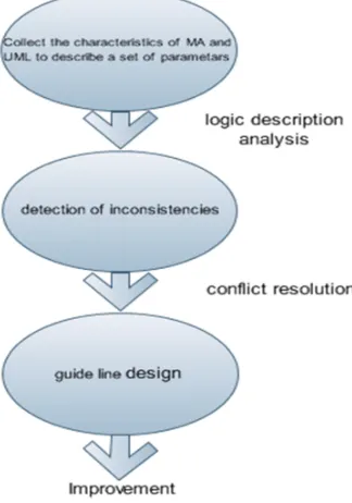
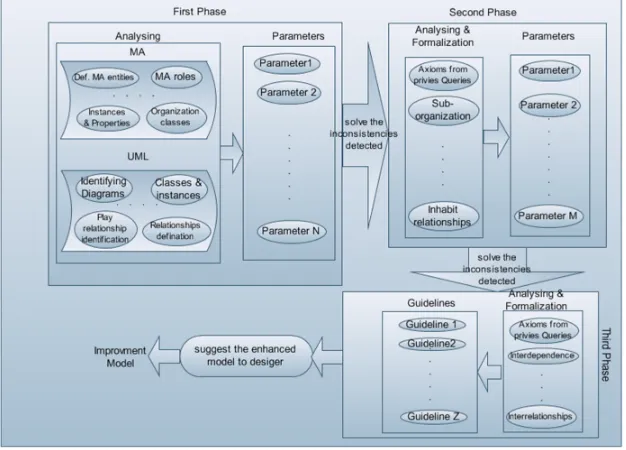
the analysis on related properties grouped into three different phases facilitates the design activity, the automatic detection of inconsistencies and the improvement of the design. Figure 1 illustrates the scenario of this method.
Figure 1. Checking method scenario
The generated specifications are created based on the specification of the Mobile Agent (MA) and on the specification of the modeling language being used to design Mobile Agent (MA). Each generated specification is composed by a phase [8] [9] [10]that specifies a set of MA and modelling language properties and parameters used to analyze the designs, according to additional set of properties. Designs are phase instances created according to the phase specification and analyzed using the queries.
In the first phase, the phase-based specifications of the proposed method is generated, which describe a minimum set of concerns and axioms, that characterize the Mobile Agent (MA) and the diagrams defined by the modeling language. In addition, such specifications also describe a set of parameters used to analyze the design according to Mobile Agent (MA) properties, and modeling language intra-model properties that were not described in this phase. Mobile Agent (MA) properties characterize the Mobile Agent (MA) by defining the Mobile Agent (MA) entities, their properties and relationships. The modeling language intra-model properties fully specify the characteristics of each modeling language diagram by stating, for instance, the classes and the relationships that can be modeled in each static (structural) diagram.
In phase two, the design is analyzed according to the modeling language inter-model properties. Inter-model properties identify the interdependencies between the diagrams. Such properties state, for example, that an entity modeled in a given diagram, must also be modeled in another diagram. The result generated in this phase contemplates all the Mobile Agent (MA) properties, together with all the modeling language intra-model properties, while the parameters are used to evaluate the design according to inter-model properties.
In phase three, the design is analyzed according to the compliance with designers’ guidelines rules. The generated phases define all the Mobile Agent (MA) and intra-model properties already stated in the second phase, together with the modeling language inter-model properties. Parameters are used to describe the set of design properties, that provide guidelines to the designers to improve their models.
© 2015, IJCSMC All Rights Reserved
1103
2. THE DESIGN CHECKING METHOD OVERVIEW
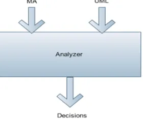
The validation approach design checking method provides support for the analysis of MOBILE AGENT (MA) designs, represented by modeling languages. The method is based on the specification of MOBILE AGENT (MA) and on the specification of the modeling language being used to design the MOBILE AGENT (MA) . By analyzing the designs according to both specifications, it is possible to check both the MOBILE AGENT (MA) properties (independently of the modeling language) and the modeling language properties themselves. Figure 2-a illustrates an overview of the method [11] .
Figure2-a. The overview of design checking method
The specification of MOBILE AGENT (MA) is described by the TAO met model [11]. Such metamodel relates agents and its associated abstractions with objects while defining the main MOBILE AGENT (MA) entities (agents, organizations, environments, objects, agent roles and object roles), their properties and relationships (specialization, association, aggregation, dependency, play, control and ownership).
The modeling language specification is also based on a met model that describes the properties and characteristics of the language. In order to illustrate our approach, the modelling language being used in this paper is Mobile Agent Modelling Language (ML) [12] [13]. ML extends UML by including the agent related abstractions identified in TAO. The MA-ML met model describes the artefacts (or diagrams) that are used to express both the structural and the behavioral aspects of MA. MA-ML defines three structural diagrams (i.e., the UML extended class diagram, organization diagram and role diagram) and two dynamic diagrams (i.e., the UML extended sequence and activity diagrams), as in Figure 2-b.
© 2015, IJCSMC All Rights Reserved
1104
Both specifications – MA and modeling language specifications – are represented by using phases and related parameters. The use of phases to formalize the MAs and the modeling language is justified through the direct translation from design models into phase instances and, consequently, the generation of knowledge-bases (KBs) that can be manipulated by using the reasoning services that are available for this kind of data.
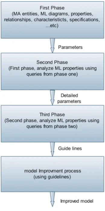
In Figure 3 below, and in the following paragraphs, we provide model details about the three phases of our validation method. In phase one, the design is analyzed according to both the MA properties, and the modeling language intra-model properties, using parameters. In this phase we identify the MA entities, properties and relationships as well as the modeling language diagrams.
In phase two, the design is analyzed according to the modeling language intermodel properties by using parameters. Such analysis begins when the analysis of the first phase is completed, and the design is updated according to the inconsistencies detected during the first phase. The second phase is an extension to the first phase, where it describes all MA and modeling language intramodel properties.
In phase three, the design is analyzed by using detailed parameters to provide guidelines to the designer to improve his/her models. Phase three only begins after the design has been updated according to the inter-model inconsistencies found in phase two. This phase is an extension of the second phase and it specifies the MA properties and all modeling language (intra and inter-model) properties.
© 2015, IJCSMC All Rights Reserved
1105
To formalize the specification of the MA and the modeling language, we adopted Description Logics (DL) [14], because it is a decidable subset of first order logic and there is a recommendation from OMG [15] to using a DL-based language Web Ontology Language (OWL) [16], as a standard for phase description. Phases are represented by concepts, properties and axioms, where properties represent the relationships between the concepts and axioms represent the constraints over the concepts and relationships. Therefore, the phases that support the validation approach are described using a state-of-the-art DL reasoning system [17] .
3. PHASE ONE:ANALYSING MASPROPERTIES AND INTRA-MODEL PROPERTIES
This phase partially formalize the MA by describing MA entities’ classes, together with their instances and properties, and the relationships that can be used between them. The phase does not fully formalize the MAS, since it does not state the rules (or axioms) that are associated with the entities’ properties and relationships. For instance, although the phase identifies the relationships, it does not describe which entities can be linked by those relationships.
In addition, this phase briefly presents the modeling language being used by identifying the diagrams that it defines. The phase does not completely specify the modeling language, because it does not describe rules related to intra and inter-model properties.
The design produced using the described phase is, therefore, a MA design, since it uses MA abstractions defined in the phase. However, such a design may not be consistent with MA properties and with the modeling language properties, since the phase does not describe axioms that guarantee such consistence. For that reason, queries are described and associated with the phase to analyze the design and detect any MA or intra-model inconsistence. The detection is automatically provided by the reasoning services from the DL-based system (RACER), where the parameter answer informs the designer where the inconsistencies are.
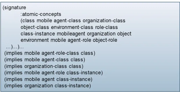
3.1 FIRST PART
As stated before, the phase partially specifies the MA and the modeling language. The phase identifies, for instance, the entities’ classes, the entities’ instances and the relationships that link those entities. Figure 4 and Figure 5 illustrate two parts of the phase that correspond to the specification of MA properties. Figure 4 depicts the definition of Mobile Agents, Mobile Agent roles and organizations classes and instances, while Figure 5 shows the play relationship identification. The classes, instances and relationships definitions are based on TAO.
The phase also describes some modeling language properties by identifying the diagrams proposed in the modeling language. Figure 6 illustrates the three static diagrams defined in MA-ML by stating that classes and relationships can be modeled in such diagrams.
© 2015, IJCSMC All Rights Reserved
1106
Figure 5. Identification of the play relationship
Figure 6. Identification of MA-ML static diagrams
3.2 SECOND PART THE INTRA-MODEL PARAMETERS
While describing the phase in the previous section, the relationships were not completely specified. The phase only states the available relationships but does not describe the entities that can be linked by them. It is an example of a MAS domain property that can be analyzed by using queries. Figure 7 illustrates parameter I that detects the play relationships that are not correctly used. The play relationship relates agent, sub-organization or objects to agent roles or object roles. By using the parameter, it is possible to analyze the design and detects the play relationships that are not being used according to the specification.
© 2015, IJCSMC All Rights Reserved
1107
Figure 7. (Parameter I) Play relationship
Figure 8. (Parameter II) Organization diagram
4. PHASE TWO:ANALYSING INTER-MODEL PROPERTIES
Phase two should begin only after all inconsistencies detected at phase one have been solved. In this context, the phase instance that represents the design, has no MA or intra-model inconsistencies. However, it is possible that some inter-model inconsistencies remain since inter-model properties have not been analyzed yet. In order to guarantee that the method instance being used in this phase has not MAS domain or intra-model inconsistencies, the rules described by the parameters used in phase one were transformed into axioms of the method used in phase two. The method used in this phase fully formalizes the MAS domain and the intra-model properties of the modeling language. Parameters are used in this phase to analyze the design according to the inter-model properties that have not been checked yet.
4.1 THE SECOND PHASE
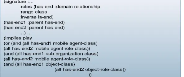
This phase is an extension of phase one through the addition of new axioms defined, based on the parameters of phase one. In order to exemplify the second phase, consider parameters I and II described in Section 3.2. These parameters are transformed into axioms to formalize the play relationship (Figure 9) and the organization diagram (Figure 10). Figure 9 shows the method part which specifies that the play relationship can be used to link agents to agent roles, or sub-organizations to agent roles, or objects to object roles. Figure 10 illustrates the phase part describing that the organization diagram can be used while modeling any class and the play, ownership and inhabit relationships.
© 2015, IJCSMC All Rights Reserved
1108
Figure 10. Formalization of organization diagram
4.2 THE INTER-MODEL PARAMETERS
Since the MA and intra-model properties are already described in the phase axioms, it is now necessary to analyze the design according to the modeling language inter-model properties. Such properties state restrictions between the modeling diagrams. Figure 11 illustrates one of the inter-model properties that relate two static diagrams – the role and the organization diagrams. Parameter III analyzes the design to find out if there is an agent role class defined in a role diagram and not defined in an organization diagram. MA-ML metamodel states that every role must be defined in an organization diagrams.
Figure 11. (Parameter III) Interdependence between role and organization diagrams
Another example of an inter-model property is described in parameter IV (Figure 12) and relates a static diagram to a sequence diagram. Parameter IV analyzes the design to realize if there is an instance in a sequence diagram that is instance of a class that does not appear in at least one static diagram. MA-ML metamodel defines that any instance must be an instance of a class modeled in one of the three static diagrams.
Figure 12. (Parameter IV) Interdependence between static and sequence diagrams
5. PHASE THREE:ANALYSING WELL-FORMED RULES
© 2015, IJCSMC All Rights Reserved
1109
5.1 THE THIRD PHASE
The operation described in this phase is an extension of the second phase through the addition of new axioms defined, based on the parameters described in the second phase. Such parameters are transformed into axioms to formalize the interrelationships between static diagrams, and between static and sequence diagrams. Figure 13 illustrates the formalization of the interdependence between role and organization diagrams described as parameter in Parameter III. Figure 14 depicts the formalization of the interdependence between static and sequence diagrams described as parameter in Parameter IV.
Figure 13. Formalization of interdependence between role and organization diagrams
Figure 14. Formalization of interdependence between static and sequence diagrams
5.2 THE DESIGN GUIDELINES
The set of design rules is formally encoded in parameters in order to analyze the design and provide good design practices. Since the designs of Mobile Agent applications tend to be very complex, the design analysis can also be used to detect ill-structured design representations that can be replaced by structures recognized as good designed practices described in the set of rules. In this paper, we present an example of such parameters as a case study, therefore we formalize a general model as in the next section.
6. GENERAL PROPOSING MODEL FOR CHECKING UML-BASED MOBILE AGENT
A general proposing model is illustrated in figure 15 as a validation approach for checking UML-based Mobile Agent, which contains a systematic previous three phases, as a guidelines suggesting the improvement of the model.
Figure 15. Proposing A General Model for checking UML-based Mobile Agent
(implies (and mobile agent-role-class (some is-class role-model))
© 2015, IJCSMC All Rights Reserved
1110
7. RELATED WORK AND OUR WORK (HISTORICAL OVERVIEW)
Dong and colleagues [18] show that it is possible to check method properties by defining theorems Z/EVES that relate method classes and roles. They check the static (or structural) part of the method which means class (concept) inconsistency, subsumption and instantiation testing. Also, they defined the Z semantics for the DAML+OIL language primitives and their associated constraints to check if the method definition is according to them and verify methods coded in DAML+OIL [19].
Our approach allows not only the checking of structural properties of the models, but some dynamic properties as well. Also, this research is related to theirs in the sense that we define the semantics for an MAS modeling language metamodel, with its associated diagrams and constraints using a DL-based language to check if the design models coded in that modeling language, and translated to DL are consistent with their metamodel. We use a DL reasoner and its associated reasoning services to perform the automatic checking of such models, combined with a list of pre-defined parameters.
Kalfoglou and Robertson [20] methods are used to reason about domain specifications correctness. They considered the correctness of an application specification relatively to the application domain. In this sense, they propose the use of a method, which describes the application domain to guide the specification engineer. Therefore, as they are considering a formal specification for the application, that is based on a method which describes the application domain, they can automatically check the existence of methodical inconsistencies in the application specification. Considering the four layer cake of the metadata architecture from OMG-MOF [21] , their work navigates between the domain model layer (M1) and the instance layer (M0), while ours navigates between the metamodel layer (M2) and the domain model layer (M1); this means that we are considering the overall class of MAS applications, independently of the considered application domain.
Since modeling languages do not have a precise semantics yet, several works address the problem of design models verification [2][3][4][5][6]. Kim and Carrington [4] provide a translation from a UML class model to an Object-Z specification, but they don't provide means to verify the model.
This research defines method that provides a formal description of MAS design models, which uses knowledge-based reasoning techniques to verify these models consistency.
Ekenberg and Johannesson [3]define a logic framework for determining design correctness. Their framework is described in FOL (first order logic) and it provides guidelines to translate UML models, and to detect some inconsistencies in the models. Their framework is general and the use of the translation rules depend on the designer skills in FOL, since there is not an automatic support for this activity yet.
We define a method description language based on DL, which is a decidable subset of FOL. The translation of MAS design models to the method description language, can be done automatically by using systems such as RICE [15] [22] or Protégé [22] with RACER, among others. Also, the verification of consistency is automated by applying the reasoning and inference services the generated KB.
Mens, Straeten and Simmonds[5][6]. Use DL to detect inconsistencies and to maintain consistency between UML models in a context of software evolution. Due to the context of their work, they only consider consistency checking between different models. They define the Classless instance conflict [6] as; the conflict that arises when an object in a sequence diagram is the instance of a class that doesn't exist in any class diagram. Their work related to ours in the way they check consistency between models.
Our work considers an MAS context and extends the idea of classless instance when, for example, we verify the absence, in any organization diagram, of classes that were predefined in role diagrams or class diagrams.
© 2015, IJCSMC All Rights Reserved
1111
8. CONCLUSIONSANDFUTUREWORK
This paper presents a validation approach for checking Mobile Agents based UML by three phase based method for structuring formal specifications of MAS, based on UML that describes the MAS and the metamodel of a MAS UML-like modeling language. The validation approach method is composed of three phases that support the desired flexibility during the design activity. Such flexibility allows syntactical incorrectness during the creation of design models. The models themselves are checked in the first phase (by analyzing the intra-model properties) while the interrelationships between the models are checked in the second phase (by analyzing the inter-model properties). Finally, the method also provides support to the definition of design guidelines in phase three. Such guidelines are good practices of design using the modeling language.
We present a MAS-ML graphical tool, where designers could model MAS using the MAS-ML diagrams [12]. Our method provides a back-end for the tool allowing the analysis of the models during their building. Thus, the inconsistencies that arise during design construction is automatically detected, which will helps designers not even to decrease the time of building, but to improve quality of MAS designs, as well.
REFERENCES
[1] rational, "http://www.ibm.com/software/rational," [Online]. Available: http://www.ibm.com/software/rational. [Accessed 12 4 2015]. [2] D. BERARDI, "Using DLs to reason on UML class diagrams," in th KI-\2002 Workshop on Applications of Description Logics, 2002.
[3] L. EKENBERG and P. JOHANNESSON, "A framework for determining design correctness," Knowledge Based Systems, vol. 17, pp. 1-14, 2004. [4] s. KIM and D. CARRINGTON, "A Formal Mapping Between UML Models and Object-Z Specifications," in ZB'2000, International Conference of B and
Z Users,, York, UK, 2000.
[5] T. MENS, R. STRAETEN and J. SIMMONDS, "Maintaining Consistency between UML Models with Description Logic Tools," in the Workshop on Object-Oriented Reengineering at ECOOP 2003, 2003.
[6] R. STRAETEN and J. SIMMONDS, "Detecting Inconsistencies between UML Models Using Description Logic," in THE 2003 INTERNATIONAL WORKSHOP ON DESCRIPTION LOGICS, 2003.
[7] R. Steven, C. Mark and R. Frank, "Designs for explaining intelligent agents," agents international journal of human-Computer Studies, vol. 76, no. 1, 2009.
[8] W. BORST, "CONSTRUCTION OF ENGINEERING ONTOLOGIES FOR KNOWLEDGE SHARING AND REUSE," University of Twente, Enschede, 1997.
[9] T. GRUBER, "A Translation Approach to Portable Ontology Specification," Knowledge Acquisition, vol. 5, pp. 199-220, 1993.
[10] A. Estefania and J. Vicente, "Vicente Botti Multi-agent System Development Based on Organizations," Electronic Notes in Theoretical Computer Science,
vol. 150, pp. 55-71, 2006.
[11] M. Al-Kholy, A. Khalifa and M. Alsaid, "Mobile Agents Security in Internet," Msc. Thesis, Systems and Computer Engineering Department, Faculty of Engineering, Al-Azhar University, Cairo -Egypt, 2011.
[12] V. SILVA, A. GARCIA, A. BRANDÃO and C. CHAVEZ, "Taming Agents and Objects in Software Engineering," in Software Engineering for Large-Scale Multi-Agent Systems, Springer Berlin Heidelberg, 2003, pp. pp 1-26.
[13] V. SILVA and C. LUCENA, "From a Conceptual Framework for Agents and Objects to a Multi-Agent System Modeling Language," Journal of Autonomous Agents and Multi-Agent Systems, vol. 9, pp. 145-189, 2004.
[14] A. Yang, Braunschweig, Fraga and Guessoum, "Stalker A multi-agent system to facilitate component-based process modeling and design," COMPUT CHEM ENG, vol. 23, no. 10, 2008.
[15] F. BAADER, D. CALVANESE and D. MCGUINESS, The description Logic Handbook – Theory, Implementation and Applications, Cambridge Univ, 2003.
[16] "OBJECT MANAGEMENT GROUP – OMG," [Online]. Available: http://www.omg.org/. [Accessed 12 4 2015].
[17] W3C, " OWL Web Ontology Language," 10 2 2004. [Online]. Available: http://www.w3.org/TR/owl-features/. [Accessed 22 5 2015]. [18] "RACER, Renamed Abox and Concept Expression Reasoner," 2015. [Online]. Available: http://www.sts.tu-harburg.de/~r.f.moeller/racer.
[19] J. DONG and C. LEE, "Verifying DAML+OIL and Beyond in Z/EVES," in the 26th International Conference on Software Engineering (ICSE’04), 2004. [20] "The DARPA Agent Markup Language," DARPA's Information Exploitation Office., 2006. [Online]. Available: http://www.daml.org/. [Accessed 2015]. [21] Y. KALFOGLOU and D. ROBERTSON, "A case study in applying ontologies to augment and reason about the correctness of specifications," in of the
11th International Conference on Software Engineering and Knowledge Engineering (SEKE99), Kaiserlautern, Germany, , 1999. [22] "OBJECT MANAGMENT GROUP: OMG – Meta Object Facility (MOF) Specification, version 1.4," 2002. [Online]. Available:
http://www.omg.org/cgibin/doc?formal/2002-04-03 . [Accessed 2015].