Available Online at www.ijcsmc.com
International Journal of Computer Science and Mobile Computing
A Monthly Journal of Computer Science and Information Technology
ISSN 2320–088X
IJCSMC, Vol. 4, Issue. 2, February 2015, pg.188 – 197
RESEARCH ARTICLE
SPRITE REGION ALLOCATION USING
MOTION COMPENSATION TECHNIQUE
Zainab J. Ahmed
1, Loay E. George
21,2Dept. of Computer Science, College of Science, University of Baghdad, Baghdad, Iraq
1 [email protected]; 2 [email protected]
Abstract— In this paper, the developed sprite allocation method is designed to be coherent with the introduced block-matching method in order to minimize the allocation process time for digital video. The accomplished allocation process of sprite region consists of three main steps. The first step is the detection of sprite area; where the sequence of frames belong to Group of Video sequence are analysed to detect the sprite regions which survive for long time, and to determine the sprite type (i.e., whether it is static or dynamic). Then as a second step, the flagged survived areas are passed through the gaps/islands removal stage to enhance the detected sprite areas using post-processing operations. The third step is partitioning the sprite area into blocks. Several interesting control parameters were taken into consideration to study the performance of the suggested sprite region allocation schemes. The tests indicated that the proposed sprite area allocation method can easily detect the sprite area with low processing time requirements and good quality performance.
Keywords— Sprite, Block Matching, MPEG-4, Group of Video, Static, Dynamic
I. INTRODUCTION
Several algorithms have been developed to handle the problem of sprite allocation. Farin and De proposed an algorithm that provided an optimal partitioning of a video sequence into independent background sprites (a multi sprite), the algorithm resulted in a significant reduction of the involved coding cost. Additionally, the proposed sprite-generation algorithm ensured that the sprite resolution is kept high enough to preserve all details of the input sequence, which is a problem that especially arises during the camera zoom-in operations. Even though their sprite generation algorithm created multiple sprites instead of only a single background sprite, it is fully compatible with the existing MPEG-4 standard [6]. Glantz et al evaluated some of the automatic object segmentation methods based on global motion estimation and background sprite generation. The objects coded using MPEG-4 Visual Main Profile and compared with the Advanced Simple Profile. The main challenge is the segmentation of the foreground objects during the preprocessing step [7]. Khatoonabadi and Bajić proposed an efficient framework for constructing a sprite-based visualization of the object's trajectory from the compressed video data stream. The background sprite is generated using a limited amount of information from the compressed video stream (i.e., the motion vectors extracted from each frame) and the pixel values taken from a selected subset of frames. Global motion parameters are estimated using a combined motion vector-based and pixel-based approach, and then they used to map decoded pixel values to the sprite. Meanwhile, the trajectory of a moving object is estimated using an efficient method based solely on the decoded motion vectors and the coding modes. They overlaid onto the sprite to indicate the path traversed by the object [8].
The objective of this paper is to introduce a simple and fast method to allocate sprite objects (or areas) in the reference frame of each Group of Video (GOV); the system allocates the sprite blocks using motion compensation information The rest of this paper is organized as follows: Section II explains the layout of the proposed sprite region allocation system, its workflow and describes the steps of the proposed system. The established proposed system is tested on two commonly used video samples. The test results are listed and discussed in Section III, finally the derived conclusions are given in section IV.
II. THE PROPOSED SPRITE REGION SYSTEM
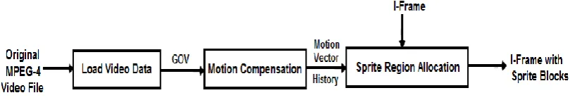
The layout of the proposed system is illustrated in Figure (1). It has three primary modules. They contain the essential stages whose tasks are focused toward allocating the sprite blocks. Firstly, a set of video processing operations are applied in order to prepare the video data for application of motion compensation. In order to avoid coding time delay, it is important to simplify the task of motion compensation. Secondly, motion compensation is applied to assess the motion vectors of the blocks that belong to predictive frames. The determined motion vectors are used for registering the motion history of all blocks in order to find out the survived region (i.e., sprite regions) in I-frame. Three variants for the motion compensation method have been introduced; they are the 8-Neighbor (8-N), 4-Neighbor (4-N) and Hybrid Search (HS)). Thirdly, the sprite region is identified and flagged. In the following the main stages of the developed system are given:
Fig. (1): The Layout of Proposed System
A. Load Video Data Module
The video frames belong to GOV are represented using BMP raster format. Each GOV consists of N frames (in this paper it was taken as 10). Then, the values of the gray component of the pixels belong to each frame is calculated using the following equation [9]:
( ) (( ( ) ( ) ( ) ) ) ( )
B. Motion Compensation Module
algorithm is called 8-Neighbor Search (8-N) and the second called 4-Neighbor Search (4-N). In 8-Neighbor method, the eight surrounding neighbor blocks (but in the previous frame) are used to assess the initial search position of the target block (belong to current frame) to find the best matched block (lay in previous frame). The suggested 4-Neighbor search method differs from the proposed 8-neighbor search in:
1. Beside the initial position, determine the MAE of the 4-nearest neighbor blocks adjacent to the initial block.
2. Beside the 4-neighbors blocks, one of the 4-diagonal neighbors (i.e., the corner that close to the two pretested points have lowest MAE) will be included in the tests.
Also a hybridization that mix the proposed two predictive mechanisms (i.e., 8-N and 4-N searches) with the exhaustive search (ES) mechanism is adopted, this mix is to (i) gain matching accuracy close to ES, (ii) get search time (ST) less than that of ES and (iii) it offers more error-time control capability [10].
C. Sprite Region Allocation Module
The strategy of sprite region allocation is based on segmenting the video frames into foreground and background objects. The main objective is to generate the background sprite with better quality. Although, the sprite region is located and isolated from the rest of the frames by making detection process, but it is very difficult to completely eliminate the effects of foreground objects; which significantly deteriorates the quality of sprite images. So, a post processing process is necessary to eliminate the produced gaps/pores and, consequently, enhances the sprite allocation process result.
Theproposedsprite detection systemconsists of three main stages: (i) Sprite Blocks Nomination (SBN), (ii)
Gaps Filling and Islands Remove (GFIR) and (iii) Partitioning the Sprite Area into Blocks (PSAB).
Stage-1:The Stage of Sprite Blocks Nomination
This stage analyses frames sequence of GOV by partitioning the frames into regions (or objects) in order to decide which of these blocks represent the sprite. This stage is necessary to determine sprite regions that remained survive for long time in GOV. This stage consists of two essential steps: (a) Motion vectors analysis
(b) Sprite area decision.
Stage-1a: Motion Vector Analysis
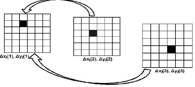
The outcomes of motion compensation have been used as key data for tracking the motion history of all scene blocks in order to detect the survived blocks. For each tested jth block belong to ith frame the accumulated motion vector (Δx'j(i), Δy'j(i)) is determined from the relative motion vector (Δxj(i), Δyj(i)):
( ) {
( ) ( ) ( ) ( )
( ) {
( ) ( ) ( ) ( )
Where, i represents the frame number (iϵ[1, SGOV]); SGOV represents the size of GOV; jrepresents the block number (jϵ[0, NxNy-1]); where Nx is the number of blocks aligned horizontally, Ny is the number of blocks aligned vertically, and
(
)
motion vector accumulator to reflect the location of tested block in I-frame (i.e., not in previous frame). Figure (2) illustrates the motion vector accumulators.Fig. (2): An example of motion vector accumulators
As survival criteria the best (lowest) MAE (i.e., Emin) found for each block during the inter-frame stage is
accumulated motion vector (Δx', Δy') it is considered either as nominated static sprite area or as nominated dynamic sprite area. In case the best found match error (Emin) for the block is found high then the block is
considered as non-sprite area. So, the blocks classification is done by testing all pixels belong to reference (I) frame with corresponding pixels belong to other frames of GOV. The proposed steps of testing the survivability and nominating the sprite areas are:
(1) Generate two 2-dimensional counter arrays Cs(0 to Wid-1, 0 to Higt-1), and Cd(0 to Wid-1, 0 to Higt-1),
and set its elements equal to 0.
(2) For each block (j) belong to frame (i >1), if the value of its best matching result (Emin) is less than a
predefined threshold (Ethr), then that block is considered as survived block; and all the corresponding
positions of block's pixels in one of the two counter arrays (Cs or Cd) are incremented by 1. The increment decision is done according to:
(A) If the incremental motion vector (Δx'j(i), Δy'j(i)), see equation (2), is (0,0) then make increment for
the corresponding locations of Cs().
(B) Otherwise, make incrimination on the corresponding elements of Cd().
Stage-1b: Sprite Area Decision
As next step, the sprite area should be decided; first of all the collected area of the decided hosting sprite (whether it is selected static or dynamic) should be counted for generating the binary index map for I-frame (i.e., set 1 for sprite pixel, and 0 for non-sprite pixel). It is important to take into consideration that the I-frame pixels counted as static sprite area can also be considered as part of the dynamic sprite area. The applied steps of this decision method are:
Case1: If the sprite type is static; for each pixel do:
If Cs() is greater than Tdecision then set pixel as sprite pixel, otherwise set pixel as non-sprite pixel.
Case2: If the sprite type is dynamic; for each pixel do:
If Cd()+ Cs() is greater than Tdecision then set pixel as sprite pixel, otherwise set pixel as non-sprite pixel.
Stage-2: The Stage of Gaps Filling & Islands Removal
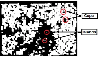
This stage includes all the necessary steps required to enhance the detected sprite regions. Due to the thresholding process applied for purpose of flagging the I-frame's pixels as sprite or non-sprite pixels, many gaps (small black areas) and islands (small white areas) will appear in the sprite-map array (as shown in Figure 3). The white color represents the sprite pixel, and black color indicates non-sprite area.
In this stage two kinds of filling/removal methods are applied. For handling isolated gap points the tilling process is applied, while for isolated island points the erosion process is applied. For small gap areas (consist of few connected black points) the seed filling method is applied to convert the points of these areas to white points. Also, the seed filling algorithm is applied to collect the small white areas (classified as sprite) and convert them to black.
Fig. (3): Gaps and islands in a constructed frame
Fig.(4): Sprite region after tiling, erosion and seed filling
Stage-3: The Stage of Partitioning Sprite Area into Blocks
In the previous stages, the reference sprite (survived) area is allocated into one large frame, and then the small and unnecessary gaps/ islands are eliminated. The sprite blocks are constructed according to simple uniform partitioning scheme, with taking the following two conditions:
(1) Avoid the construction of sprite blocks close to image boundaries.
(2) Each sprite block should mainly consist of the classified sprite pixels (with exception for small percentage of non-sprite pixel; if it is necessary).
The following sprite blocks construction steps can be performed:
(1) Partition the constructed binary sprite-map array into non-overlapped blocks; each has size (I×I).
(2)
For each block, a pixel-wise scanning is applied for counting the number of white pixels. If the ratio of the counted pixels relative to block size is above a predefined ratio; then the scanned block is considered as a sprite block and all the pixels fall in that block must re-flagged as sprite (whether they are already classified sprite or not); otherwise the block is considered as non-sprite and all its pixels are re-flagged as non-sprite.III.TESTS RESULTS
The results of motion compensation stage have been used as key data in order to detect the sprite area in I-frame. In the proposed system, the outcomes of the 8-N & ES method have been used as inputs to detect and construct sprite blocks. Many sets of tests have been conducted to achieve an efficient sprite block construction, the sprite regions must be selected properly (i.e., each block should consist of as large as possible of sprite points). The used video test samples are Family and Conference (with frame size specifications= 320x240 pixels and pixel color depth=24 bit). The system was established using C# programming language. Table (1) presents the tests results of sprite blocks construction stage. The efficiency is tested at different cases of block length (lay within the range [4,8]) and with different threshold values (i.e., threshold is the lowest count values for blocks construction); also, it was subjectively evaluated. In the set of conducted tests, the constructed blocks were compared with blocks after gaps filling and islands removal stage; the comparison must cover one of three cases:
Case-1: If the pixel in the two blocks (i.e., constructed block and it's variant after gaps filling and islands removal) is same, then this pixel will be identified as "exact".
Case-2: If the sprite pixel in the construction block (0) is not similar to the corresponding pixel after the gaps filling and islands removal stage, then this pixel will be considered "missed".
Case3: If the non-sprite pixel in construction block (1) is not similar to the corresponding pixel after the gaps filling and islands removal stage, then this pixel will be considered "added".
Figure (5) presents the frames produced by sprite construction stage. The results in table (1) show that the increase of the thresholds involved causes an increase in error rate (i.e.; error is the sum of "added" and "missed" pixels). Table (1) presents the effect of threshold at different block size cases on the error rate of the constructed sprite area.
Reference frame Threshold=12 and block size 4×4
Threshold=64and block size 8×8
a. Family video (dynamic)
Reference frame Threshold=12 and
block size 4×4
Threshold=64 and block size 8×8 b. Conference video (static)
Fig. (5): Sprite construction
Table (1) The sprite construction results using different block size
Family Video (Dynamic Video)
Block Size Threshold Points Percentage
Exact Missing Added Error
4
16 47.875 10.388 0.000 10.388
15 49.574 8.689 0.113 8.802
14 50.395 7.868 0.230 8.099
13 51.376 6.887 0.457 7.344
12 53.001 5.262 0.999 6.260
5
25 44.889 13.374 0.000 13.374
24 46.327 11.936 0.060 11.996
23 47.585 10.678 0.169 10.848
22 48.415 9.848 0.283 10.130
21 49.318 8.945 0.454 9.400
20 50.620 7.643 0.780 8.423
6
36 42.689 15.941 0.000 15.941
35 43.285 15.345 0.017 15.362
34 44.443 14.186 0.085 14.271
33 45.784 12.846 0.207 13.053
32 46.748 11.882 0.328 12.209
31 47.438 11.191 0.439 11.630
30 48.539 10.090 0.659 10.749
7
49 40.131 19.540 0.000 19.540
48 41.155 18.515 0.021 18.537
47 42.472 17.199 0.077 17.276
46 43.453 16.217 0.141 16.359
45 44.354 15.317 0.221 15.538
44 45.117 14.554 0.308 14.862
43 45.576 14.095 0.372 14.467
42 46.640 13.031 0.550 13.580
8 64 36.333 21.930 0.000 21.930
62 38.042 20.221 0.042 20.263
61 38.995 19.268 0.089 19.357
60 39.776 18.487 0.141 18.628
59 40.391 17.872 0.193 18.065
58 41.070 17.193 0.263 17.456
57 41.590 16.673 0.327 17.000
56 42.319 15.944 0.431 16.375
Conference Video (Static Video)
Block Size Threshold Points Percentage
Exact Missing Added Error
4
16 22.063 5.849 0.000 5.849
15 27.785 0.126 0.382 0.508
14 27.785 0.126 0.382 0.508
13 27.785 0.126 0.382 0.508
12 27.785 0.126 0.382 0.508
5
25 17.155 10.757 0.000 10.757
24 17.561 10.350 0.017 10.367
23 17.711 10.201 0.030 10.230
22 18.112 9.799 0.085 9.884
21 18.276 9.635 0.116 9.751
20 20.594 7.318 0.695 8.013
6
36 13.160 14.927 0.000 14.927
35 13.894 14.193 0.021 14.214
34 13.894 14.193 0.021 14.214
33 14.197 13.890 0.048 13.939
32 14.197 13.890 0.048 13.939
31 14.969 13.118 0.173 13.291
30 17.131 10.956 0.605 11.562
7
49 14.248 14.344 0.000 14.344
48 14.568 14.024 0.007 14.031
47 14.631 13.962 0.009 13.971
46 15.122 13.471 0.041 13.512
45 15.302 13.291 0.057 13.348
44 15.772 12.821 0.111 12.932
43 15.886 12.706 0.127 12.833
42 17.399 11.194 0.379 11.573
8
64 15.833 12.078 0.000 12.078
63 20.509 7.402 0.074 7.477
62 25.676 2.236 0.241 2.477
61 25.676 2.236 0.241 2.477
60 27.785 0.126 0.382 0.508
59 27.785 0.126 0.382 0.508
58 27.785 0.126 0.382 0.508
57 27.785 0.126 0.382 0.508
56 27.785 0.126 0.382 0.508
For the sprite blocks allocation stage and construction stage several control parameters have significant effect on the obtained blocks. The effects of the following control parameters have been investigated: (i) the threshold for lowest count value for sprite area decision Tdecision; (ii) the threshold of lowest count value for tilling Ttilling;
(iii) the threshold of lowest count value for erosion Terosion; and (iv) the threshold of lowest count value to fill gaps regions Tseed-filling. Table (2) presents the adopted default values of the considered control parameters.The tests have been applied on the Family video sample.
Table (2) The default values of the control parameters in sprite detection stage
Parameter Default Value Range
Tdecision 6 [1, 10]
Ttilling 5 [1, 8]
Terosion 4 [1, 8]
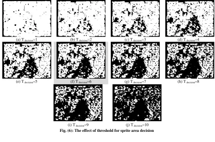
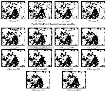
Figure (6) shows the effect of Tdecision on sprite point decision stage; the results show that when the value of Tdecision is decreased the nominated sprite region decreases. Figure (7) shows the effect of Ttillingon isolated gaps (small black areas) filling stage (using tilling algorithm). Figure (8) shows the effect of Terosionon the isolated island (small white areas) filling when using erosion algorithm. Figure (9) shows the effect of Tseed-filling on gaps elimination when using seed filling. The results indicate that when Ttilling and Terosion values are decreased then the stages of filling isolated gaps and removal of isolated islands becomes more important, while the result refers that the increase of Tseed-filling causes increase in filling/removal gaps.
(a) T decision=1 (b) T decision=2 (c) T decision=3 (d) T decision=4
(e) T decision=5 (f) T decision=6 (g) T decision=7 (h) T decision=8
(i) T decision=9 (j) T decision=10
Fig. (6): The effect of threshold for sprite area decision
(a) Ttilling=1 (b) Ttilling=2 (c) Ttilling=3 (d) Ttilling=4
(e) Ttilling=5 (f) Ttilling=6 (g) Ttilling=7 (h) Ttilling=8
Fig. (7): The effect of threshold in tilling algorithm
(e) Terosion=5 (f) Terosion=6 (g) Terosion=7 (h) Terosion=8
Fig. (8): The effect of threshold in erosion algorithm
(a)Tseed-filling=100 (b)Tseed-filling=200 (c)Tseed-filling=300 (d)Tseed-filling=400
(e)Tseed-filling=500 (f) Tseed-filling=600 (g)Tseed-filling=700 (h)Tseed-filling=800
(j) Tseed-filling=1000
(i)Tseed-filling=900
Fig. (9): The effect of threshold in seed filling algorithm
IV.CONCLUSIONS
In this paper, the proposed sprite regions allocation methods have achieved fast and outstanding sprite detection results; the tests results indicate that the methods can allocate sprite (survive) regions with better quality. For future work, Principle Component Analysis (PCA) method could be used as an engine to classify the pixels into sprite and non-sprite pixels.
REFERENCES
[1] Li, Z. N.; and Drew, M. S.; "Fundamentals of Multimedia", Pearson Prentice Hall, 2004.
[2] Al-Mualla, M.E.; Canagarajah, C.N.; and Bull, D.R.; "Video Coding for Mobile Communications Efficiency, Complexity, and Resilience", Academic Press An Imprint of Elsevier Science (USA), 2002. [3] Sikora, T.; "Trends and Perspectives in Image and Video Coding", IEEE, Vol. 93, No. 1, Pp. 6-17, January
2005.M. Wegmuller, J. P. von der Weid, P. Oberson, and N. Gisin, “High resolution fiber distributed measurements with coherent OFDR,” in Proc. ECOC’00, 2000, paper 11.3.4, p. 109.
[4] Lee, M.; Chen, W.; Lin, Ch.,B.; Gu, Ch.; Markoc, T.; Zabinsky S., I.;, and Szeliski, R.;"A Layered Video Object Coding System Using Sprite and Affine Motion Model", IEEE transactions on circuits and systems for video technology, Vol. 7, No. 1, Pp. 130-145, February 1997.
[5] Shi, Y.Q.; and Sun, H.; "Image and Video Compression for Multimedia Engineering", CRC Press, 2nd Edition, 2007.
[7] Glantz, A.; Krutz, A.; Sikora, T.; Nunes, P.; and Pereira, F.; "Automatic MPEG-4 Sprite Coding - Comparison of Integrated Object Segmentation Algorithms", Springer, Vol. 49, No. 3, Pp. 483-512, January 2010.
[8] Khatoonabadi, S.H.; and Bajić, I.V; "Still Visualization of Object Motion in Compressed Video", IEEE International Conference on Multimedia and Expo Workshops (ICMEW), Pp. 1-6, July 2013.
[9] "http://msdn.microsoft.com/en-us/library/ms893078.aspx", April, 2004.