Available online: https://edupediapublications.org/journals/index.php/IJR/ P a g e | 4912
A Combined Approach for 3D Formation Control in a
Multi-UAV System using ROS
Lanka Sunitha & Dr.Kvd Sagar
1Dept.of Electronics and Communication Engineering, Malla Reddy Engineering College & Management Sciences, Kistapur, Medchal, Hyderabad
2Dept. of Electronics and Computer ScienceEngineering, K L University
ABSTRACT
Formation control in multi-UAV systems can be obtained through different strategies, each one with its own advantages and disadvantages. In order to minimize the weaknesses of each tech-nique, this paper proposes a combined approach to drive a group of three quadrotor UAVs in a time varying formation, using a virtual struc-ture, a leader-follower strategy and two behav-ioral rules. To each UAV is assigned a position in a formation that is represented by a virtual struc-ture. The UAVs then have to compute their de-sired positions in order to achieve the formation. This is done using one of two possible meth-ods, one based on a leader-follower approach and another based on waypoints received from a ground station. Two behavioral rules are then used to move the UAVs towards their goal while avoiding collisions with each other. The algo-rithm was implemented in C++ using the ROS platform and was tested in simulations using the Pixhawk SITL simulator. Results show that the UAVs are able to move in formation and also to change the formation without colliding with each other.
1 INTRODUCTION
Recently there have being a growing interest in the use of UAVs (Unmanned Aerial Vehicles) in a wide range of appli-cations. This is due to the development of inexpensive and easy to build UAV models that can carry powerful sensors and even miniature computers. The number of proposed ap-plications is large, ranging from civil uses such as forest fire monitoring and
fighting [1][2], buildings and bridges inspec-tion [3], crop dusting [4] and search and rescue of survivors after a disaster [5], to millitary uses including surveillance and monitoring of an area [6] or even air strikes [7]. One of the most popular model both in commercial use and in aca-demic research is the quadrotor, thanks to its simplicity and great mobility.
Since the control of one UAV is already well understood, a new problem that is attracting attention is the use of a group of UAVs to perform missions. There are many advantages that come from this approach: a group carries more sensors and so is able to acquire more information about the environ-ment; the number of UAVs in the swarm can be altered to tackle missions of different levels of difficulty; if one UAV fails the remaining ones can continue the mission without it. All these advantages however come with the drawback of be-ing more difficult to control a swarm correctly than a single unit.
Available online: https://edupediapublications.org/journals/index.php/IJR/ P a g e | 4913 Most of the control algorithms proposed in
the literature can be classified as three types: leader-follower [12][13], vir-tual structure [14][15] or behavior based [16][17]. In the leader-follower strategy, one of the UAVs in the group is cho-sen as the leader. The others have to follow it and position themselves according to its position. This approach has the advantage of being easier for a human operator to drive the group, having to control only the leader. However one disad-vantage is that if the leader stops working, the whole group also stop. The virtual structure strategy consists in treating the whole group as a single fixed structure, with each UAV representing one point that composes it. The controller is de-signed such as each UAV is moved to create the structure’s desired behavior. Finally, in the behavior-based strategy the UAVs are programmed to follow some desired behavior, such as avoiding collisions or move closer to one another. In most of the cases, these kind of strategy is based in real phenomena observed in nature, and so is classified as bio-inspired.
To control a group of three UAVs while avoiding colli-sions with each other and keeping track of a time varying formation, we propose an approach that combines elements from the three mentioned strategies. The formation is treated as a rigid structure, composed by an array of poses that will be assigned to each UAV in the group. The leader is the only robot that can move freely, being controlled by an operator at a ground station or navigating autonomously. All the other
UAVs will try to move autonomously to their assigned poses in the formation, relative to the leader. The position control is behavior based, using two behavioral rules to move the UAVs: formation and separation.
The rest of this paper is structured as follow. Section 2 presents our multi-UAV system and describes our hardware and software platforms. Section 3 describes the design of the formation control strategy and the pseudocode implementa-tion of the behavioral rules. Finally, Section 4 presents the simulation environment and the obtained results.
2 MATERIALS AND
METHODS 2.1 Multi-UAV System
Our system consists of a group of robots that fly over an area and a ground station with which they communicate through a telemetry link. The ground station is responsible for collecting flight data from each robot and sending infor-mation about the desired formation, but not controlling them. The control algorithm is distributed and runs in each UAV. The objective is to move the group to a desired point, avoid-ing collisions between the UAVs and keeping a formation that can be changed over time.
The quadrotor is a simple machine, capable of vertical take-off and landing (VTOL) and moving with six Degrees of Freedom (DoF). It consists of a center body with four individ-ual rotors attached, as illustrated in Figure 1. By controlling the thrust generated by each rotor, we can lift the quadrotor and move it in the air. As shown in Figure 1, rotor i rotates anticlockwise if i is even and clockwise if i is odd. By adjust-ing the speed of the clockwise and anticlockwise rotors we can control the Yaw angle.
Figure 1: Degrees of freedom achieved by the quadrotor and rotation direction of the rotors
Available online: https://edupediapublications.org/journals/index.php/IJR/ P a g e | 4914 The robots we are developing the
algorithm to control are small quadrotors with 250mm diameter, each one using a Pix-hawk as a flight controller board. The Pixhawk is an open-source device [18] equipped with many sensors such as gyro-scope, accelerometers, magnetometer and barometer and can also be connected to a external GPS module. It runs a pow-erful software that implements the basic controller routines of the quadrotor, along with many other useful functions. In our application, the main function of the Pixhawk is to pro-vide the low-level stabilization and height control of the UAV. Figure 2 shows a photo of one of the UAVs used in our labo-ratory.
Figure 2: UAV used in the laboratory
Originally the Pixhawk is intended to be controlled by a human operator via radio controller or receive commands from a ground station. However, it is also able to communi-cate with other devices via a protocol called MAVLink. We use this protocol to send commands from an embedded Linux computer (Raspberry Pi) which is also carried by the UAV. in this way we can program the UAV to fly autonomously, while still being able to regain manual control at any time. Figure 3 shows a schematic view of the UAV components.
Figure 3: UAV components
2.3 Robot Operating System
Our algorithm was implemented in C++ and runs on the ROS platform. ROS (Robot Operating System) is an open source framework created to aid researchers in developing robotic applications [19]. ROS provides us with many tools and facilities that were very useful in our work. A ROS application is a network of independent programs, called nodes, that communicate with each other. This net-work is managed by another program called ROS Master. The communication works in a message passing way. Nodes that generate data publish this information in topics in the form of messages, while nodes that need that data subscribe to the corresponding topics and receive the published messages. The types of messages represent common data structures used in robotics, such as sensor readings or velocity commands.
In our application, the ROS system, containing all the control algorithms, runs on the Raspberry Pi. We used a node called mavros which connects to the Pixhawk via a serial con-nection and is able to translate MAVLink messages into ROS messages and vice versa. In this way the control node can get data from the Pixhawk and send commands to it. This architecture is represented in Figure 4.
Available online: https://edupediapublications.org/journals/index.php/IJR/ P a g e | 4915
3 DEVELOPMENT
3.1 Formation Control Strategy
We define a global reference frame SG with
X, Y and Z Cartesian coordinates, fixed on the ground. The position of each UAV i in the SG
frame is given by:
pG = (XG, Y G, ZG) (1) i i ii
Each robot uses its embedded sensors to locate itself in the global frame. Considering the Earth’s geometry and the origin of the SG
frame, the latitude and longitude information from the GPS sensor can be converted to values in meters in the X and Y coordinates. This gives us the robot’s initial posi-tion. From this moment on, the position will be obtained from the Pixhawk’s internal state estimator, which uses an Extend Kalman Filter to fuse the measurements from its embedded sensors, including gyroscope and accelerometers. The Z co-ordinate is obtained from the GPS and the barometer infor-mation fused together.
Each UAV receives an unique ID, which is a positive in-teger number starting at 0 and increasing in increments of 1. The formation is defined as an array of positions relative to a formation reference frame, SF . The assigned
position to each UAV is the one whose index in the formation array is equal to the UAV’s ID. In our experiments we defined three forma-tions: a horizontal line, a vertical column and a triangle.
Each UAV has to compute its desired position relative to the formation frame. We defined two methods to make this calculation:
• Leader-follower method: In this method, one UAV is considered the leader of the group (the one with ID
0). The leader ignores its position in the formation and instead is able to move freely, being controlled by an operator or following a sequence of waypoints. The other UAVs calculate their desired position relative to the
leader, considering it the origin of the formation frame.
• Waypoint method: In this method, all UAVs receive a waypoint to follow and treat it as the origin of the formation frame. There is no leader in this method. As such, this approach is more tolerant to UAV failure than the first one, however is more difficult for a human operator to drive the group.
The position of each UAV i in the SF frame
is represented by pFi . In the first position
calculation method, the origin of the SF frame
is the position of the leader, and then the desired position of each UAV i in the global frame is given by:
piDG = p0G + piF (2)
where pGiD is the desired position of UAV i
in the SG frame and pG0 is the leader’s current
position in the SG frame. In the second method,
the SF frame is centralized at the next
waypoint, so the desired position of UAV i in the global frame is given by:
piDG = pwG + piF (3)
where pG is the position of the next waypoint.
Available online: https://edupediapublications.org/journals/index.php/IJR/ P a g e | 4916 data will be used by the behavioral rules to
move the UAV.
The formation controller node also subscribes to a topic called /formation, where the ground station publishes mes-sages of type geometry msgs/PoseArray. These messages contain an array of positions representing the formation vir-tual structure. Each time a new message arrives, the forma-tion controller node updates an internal formation array vari-able, which means that the formation can be changed during the flight.
Using all the information obtained, the forma-tion controller node then uses the behavioural rules to drive the UAV by publishing a geometry msgs/TwistStamped
message in the mavros/setpoint velocity/cmd vel topic. The mavros node receives this message, creates the corresponding MAVLink message and then sends it to the Pixhawk, which will follow that command accordingly.
Since each UAV runs instances of the same nodes, it is necessary to run them under different namespaces to avoid causing conflicts. To each UAV is assigned a namespace in the form of /uavn where n is that UAV’s ID. A simplified diagram of the resulting system is shown in figure 5.
Figure 5: Simplified diagram of the ROS application gener-ated by the program rqt graph.
3.3 Algorithm Implementation
In this section we will describe how we implemented the two behavioral rules that move the UAVs together in a forma-tion.
In each loop of the control algorithm, it follows the fol-lowing steps: i. Obtain the UAV’s own pose from the Pix-hawk’s internal state estimator; ii. Determine the position of the neighbors based on the position messages received from the other UAVs; iii. Obtain the formation array from the /for-mation topic; iv. Use the behavioural rules for Cohesion and Separation to determine the direction which the UAV should move. The main loop of the algorithm is given in Algorithm 1.
First the program calls the function getPose() which cal-culates the pose of the UAV and sets the variable this.position representing the UAV’s position in the global frame. Then, the program calls another function getNeighbors() that gets the positions of the nearby robots from the received messages and stores this data in an array called neighbors.
Then the program starts calling the functions where the actual behavioral rules are implemented. Each function re-turns a vector that represent the direction that rule tells the UAV to go. For example, the Separation rule urges the UAV
Algorithm 1 Main loop of the formation control algorithm
1:procedure SWARM
2: getPose()
3: getNeighbors()
4: getFormation()
5: v1 ← separation()
6: v2 ← cohesion()
Available online: https://edupediapublications.org/journals/index.php/IJR/ P a g e | 4917 9:end procedure
to move away from its neighbors, so the separation() function will return a vector pointing to the opposite direction of the other UAVs. Each function will be explained in detail ahead.
In line 7 the two vectors are combined trough a weighted sum to generate the final resulting direction the robot should move. The weight applied to each rule determines how much that rule influences the final result. The values of the weights can be changed to obtain different results. Rules can be even completely removed from the calculation by setting its weight to zero.
In line 8 the calculated resulting direction is passed to an-other function that moves the UAV. This function publishes velocity commands to the mavros package, which in turn send MAVLink messages to the flight controller board, instructing it to move the UAV.
The implementation of each rule and its corresponding function will be explained in detail:
Separation Rule: This rule urges the robot to move away from other robots to avoid collisions. This is done creating a vector for each one of the detected neighbors pointing to the exactly opposite direction of that neighbor. These vectors are then combined into a resulting vector and returned to the main program. The implementation is shown in Algorithm 2.
Algorithm 2 Separation Rule
1:procedure SEPARATION
2: Vector v ← 0
3: for all neighbors n do
4: vn ← this.position − n.position
5: vn.normalize()
6: vn ← vn ∗ distance(this, n)
7: v ← v − n
8: end for
9: return v
10: end procedure
We also want the robot to move faster the closer it is from its neighbor. We do this by adjusting the vector’s magnitude. First we normalize it so it becomes a unit vector. Then we divide it by the distance between the two robots. As the dis-tance between two robots gets smaller, the magnitude of the resultingvector becomes bigger.
4.RESULTS AND DISCUSSION
Formation Rule: This rule tries to move the robot to its desired position in order to maintain the formation. The im-plementation is shown in Algorithm 3. Fist we test which method is being used to determine the desired position. Then we check if the UAV is the leader by testing if its ID is 0. If the method being used is the leader-follower, the leader fol-lows the waypoint and the followers determine their desired position according to Equation 2. If the waypoint method is being used, all UAVs use Equation 3 to determine their de-sired position. The function then generates a vector pointing to the calculated position.
Algorithm 3 Formation Rule
1:procedure FORMATION
2: Vector v ← 0
Available online: https://edupediapublications.org/journals/index.php/IJR/ P a g e | 4918 4: if leader-follower then
5: if ID == 0 then
6: DesiredPosition ← waypoint
7: else
8: DesiredPosition ← leader.position + Formation[ID]
9: end if
10: else
11: DesiredPosition ← waypoint + Formation[ID]
12: end if
13: v ← DesiredPosition − this.position
14: return v
15: end procedure
3.4 Computational Complexity and Communication issues
One important concern when designing a multi-robot con-trol application is the elevation of the computational com-plexity with the increase in the number of robots. In spe-cial, in a behavior based approach such as the one we used, each individual has to iterate through all other individuals to compute its behavioral rules. If a centralized control is used, this represent a O(n2) computational complexity,
where n is the number of robots. However, in a decentralized approach, each robot runs its own control algorithm with a computa-tional complexity of O(n). This means that a decentralized approach can make the system more scalable, with the addi-tion of more robots bringing a smaller burden to the process.
Another concern is the influence of delayed communica-tions. In our application the robots must communicate with one another to be able to locate their neighbors. Since we performed our tests in simulation, the communication delay was not a problem. However, in real life implementations the system would be negatively influenced by this delay. In Sec-tion 5 we discuss how this problem could be tackled in future works.
We decided to run our program in simulation first as a proof-of-concept and also as a way to evaluate its perfor-mance. We used the Pixhawk SITL (Software In The Loop) simulator, a software that is provided as part of the Ardupilot project. With it we were able to interact with a simulated Pix-hawk running its original firmware and generating accelerom-eter, gyroscope, GPS and other sensors data. Three instances of the simulator were executed simultaneously, each one us-ing a different GPS starting position, effectively simulating three UAVs that were able to be controlled individually by our ROS application.
Available online: https://edupediapublications.org/journals/index.php/IJR/ P a g e | 4919 Figure 6: Visualization of simulated UAVs
in RViz.
To evaluate the performance of our algorithm we defined two main tests.
4.1 Moving in Formation
The first test aims to evaluate the capability of the UAVs to maintain a formation while moving together. The robots are commanded
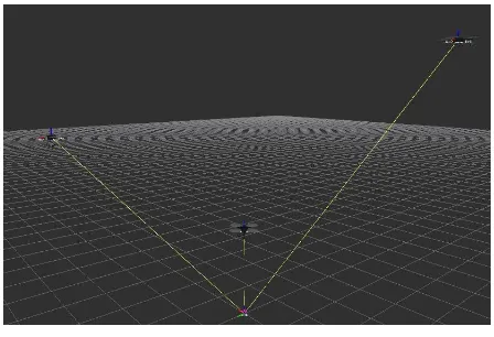
to assume a formation and then move to two waypoints. We repeated this test for each position calculation method and for three different formations: a horizontal line, a vertical column and a triangle. In all experiments the UAVs were capable of maintaining the formation and no collision occurred. In Figure 7 we show the trajectory developed by the UAVs in the test with the triangle formation and leader-follower position calculation method.
Transition Time [s] line → column 7.16 line → triangle 3.66 column →
triangle 4.90
column → line 4.70 triangle → line 3.53 triangle →
column 7.17
Available online: https://edupediapublications.org/journals/index.php/IJR/ P a g e | 4920 Figure 7: UAVs trajectory over time.
Another interesting feature of our solution is the possibil-ity of formation control in three dimensions. In figure 8 the three UAVs are keeping a vertical formation, assuming differ-ent positions in the Z axis.
Figure 8: UAVs performing a vertical formation.
4.2 Changing Formations
In this test we tried to see if the UAVs were capable of changing from one formation to another without colliding with each other. The UAVs started at the line formation, then changed to other formations following this sequence: col-umn, triangle, line, triangle, column and then line. Table 1 shows the time spent in each formation change. Thanks to the separation behavior, no collision was observed.
It is interesting to note that the longer times appear in the transitions to the column formation. This is caused by the fact that this formation is actually vertical, so the UAVs have to gain height in order to assume their desired positions.
5 CONCLUSION
This paper presented the design of a combined approach to the formation control problem in a group of UAV vehi-cles. Our algorithm combined elements from three different multi-UAV control strategies: leader-follower,
virtual struc-ture and behaviour-based. The implementation was tested in simulations and presented good results. The UAVs were able to move in different formations and change from one forma-tion to another without colliding with each other.
In future works some improvements can be studied, such as the use of cameras or range sensors to detect nearby robots. This would eliminate the need of communication between the robots, avoiding the negative influence that delayed commu-nications would have in real systems, and enable the possibil-ity to detect obstacles in the path.
ACKNOWLEDGMENTS
The authors would like to thank the institution CAPES for providing research grant and LMI for providing the necessary resources for the development of the research.
REFERENCES
[1]Merino, L., Caballero, F., De Dios, J. R. M., Maza, I., Ollero, A. Automatic forest fire monitoring and mea-surement using unmanned aerial vehicles, Proceedings of the 6th International Congress on Forest Fire Re-search: 2010.
[2]Ollero, A., Merino, L. Unmanned aerial vehicles as tools for forest-fire fighting, Forest Ecology and Man-agement: p. 263, 2006.
[3]Choi, S. S., Kim, E. K. Building crack inspection using small UAV, 2015 17th International Conference on Ad-vanced Communication Technology (ICACT): 235-238, 2015.
Available online: https://edupediapublications.org/journals/index.php/IJR/ P a g e | 4921 Vehicles Developments (APUAVD):
298-301, 2015.
[5]Baker, C., Ramchurn, G., Teacy, L., Jennings, N. Plan-ning search and rescue missions for UAV teams: 2016.
[6]Geng, L., Zhang, Y. F., Wang, P. F., Wang, J. J., Fuh, J. Y., Teo, S. H. UAV surveillance mission planning with gimbaled sensors, 11th IEEE International Conference on Control & Automation (ICCA): 320-325, 2014.
[7]Li, T., Jiang, J., Zhen, Z., Gao, C. Mission planning for multiple UAVs based on ant colony optimization and improved Dubins path, 2016 IEEE Chinese Guid-ance, Navigation and Control Conference (CGNCC): 954-959, 2016.
[8]Kushleyev, A., Mellinger, D., Powers, C., Kumar, V. To-wards a swarm of agile micro quadrotors, Autonomous Robots: 287-300, 2013.
[9]Burkle,¨ A., Segor, F., Kollmann, M. Towards au-tonomous micro uav swarms, Journal of intelligent & robotic systems: 339-53, 2001.
[10] Vas´arhelyi,´ G., Viragh,´ C., Somorjai, G., Tarcai, N., Szor¨enyi,´ T., Nepusz, T., Vicsek, T. Outdoor flocking and formation flight with autonomous aerial robots, IEEE/RSJ International Conference on Intelli-gent Robots and Systems: 3866-3873, 2014.
[11] De Benedetti, M., D’Urso, F., Messina, F., Pappalardo, G., Santoro, C. UAV-based Aerial Monitoring: A Per-formance Evaluation of a Self-Organising Flocking Al-gorithm, 10th International Conference on P2P, Parallel, Grid, Cloud and Internet Computing: 248-255, 2015.
[12] Gu, Y., Seanor, B., Campa, G., Napolitano, M. R., Rowe, L., Gururajan, S., Wan, S. Design and flight test-ing evaluation of formation control laws, IEEE Trans-actions on Control Systems Technology: 1105-1112, 2006.
[13] Ambroziak, L., Gosiewski, Z. Two stage switching con-trol for autonomous formation flight of unmanned aerial vehicles, Aerospace Science and Technology 46: 221-226, 2015.
[14] Egerstedt, M., Hu, X., Stotsky, A. Control of mo-bile platforms using a virtual vehicle approachm, IEEE transactions on automatic control: 1777-1782, 2001.
[15] Askari, A., Mortazavi, M., Talebi, H. A. UAV forma-tion control via the virtual structure approach, Journal of Aerospace Engineering: v. 28, n. 1, p. 04014047, 2013.
[16] Balch, T., Arkin, R. C. Behavior-based formation con-trol for multirobot teams, IEEE transactions on robotics and automation: 926-939, 1998.
[17] Viragh,´ C., Vas´arhelyi,´ G., Tarcai, N., Szor¨enyi,´ T., Somorjai, G., Nepusz, T., Vicsek, T. Flocking algo-rithm for autonomous flying robots, Bioinspiration & biomimetics: v. 9, n. 2, p. 025012, 2014.
[18] Pixhawk homepage:
https://pixhawk.org/. Acessed: September, 2016.
[19] ROS homepage: